

Patriot FMCTH-12, FMCTH-24, FMCTH-36 User Manual
Gas Countertop Hot Plates
This manual contains important information regarding
your Patriot unit. Please read the manual thoroughly
prior to equipment set-up, operation and maintenance.
Failure to comply with regular maintenance guidelines
outlined in this manual may void the warranty.
PLEASE READ!!!

WARNINGS
•
Do not store or use gasoline or other flammabl e vapors or liquids in the vicinity of this or any other equipment.
•
Improper ins t all at ion, adjustme nt, alteration, ser vice or maintenance can cause property dam a ge , i njury or death.
•
Read the inst all at ion and mainte na nce instructions thoroughly before installing or s e rvicing this equipment.
•
Have the equipment installed by a qualifie d i ns taller in accordance with all federal, state and loc al codes.
•
Do not install or use with out all 4 legs.
•
This equipment is for use in non-combustible locations only.
•
Do not obstruc t the flow of combustion and ventilation air .
•
Do not spray c o ntrols or the outside of the equipment with li q uids or cleaning agents
•
Allow for hot parts to cool before clea ni ng or moving.
•
This equipment should only be used in a flat, le ve l position.
•
Do not operate unattended.
•
Any loose dirt or metal particles that are allowed to enter the gas lines on this equipment will damage the valve and
affect its oper a tion.
•
If you smell gas, follow the instructions provided by the gas supplier. Do not touch any electrical switch; do not try
to light the burne r ; do not use a tele phone within cl ose proximity.
•
Never attem pt to move grate s while cooking.
SET UP
1. Remove all packing material and tape, as w ell as any protective plastic from the equipment.
2. Place the equipment in the desired position and height.
3. Install the four (4) legs onto the equipment.
4. Clean and dry the equipment thoroughly before using.
INSTALLATION:
The installation of this equipment must conform with local cod es, or wi th t he Na tion al G as Code , ANS IZ 223.1/ NFPA 5 4, or the
Natural Gas and Pr opan e I nstal lati on C ode, C SA B 149. 1, as ap pli cabl e.
• The equipment and its individual shutoff valve must be disconnected from the gas supply piping system during any pressure testing of
that system at test pressures in ex cess of ½ psi (3.5 kPa).
• The equipment must be isolated from th e g as su pply pipin g sy st em by cl osing i ts indi vidu al m anual shu toff valv e du rin g any pres su re
testing of the gas supply piping system at test pressures equal to or less then ½ psi (3.5 kPa).
Clearance and positioning around the equipment:
• This equipment must be installed adjacent to non-combustible su rfaces only with a minimum spacing of 6” from all sides. This
equipment must be a distance of 6” from other equipment. The equipment must have the 4” legs in stalled and be placed on a non combustible surface.
Air Supply and ventilation:
• The area in front and around the equipment must be kept clear to avoid any obstruction of the flow of combustion an d ventilation air.
• Adequate clearance must be maintained at all times in front of and at the sides of the equipment for servici ng and proper ventilation.
Pressure Regulator:
• All commercial cooking equipment must h ave a pressure regu lator on the incom ing service line for saf e and eff icien t operation. The
regulator provide d f or th is equipment is adaptable for both Natu ral gas an d LP gas.
• Regulator specifications: ¾” NPT inlet and outlet, factory adjusted for 5” WC Natural Gas stan dard and may be converted by
qualified personnel to be used for Propane at 10” WC.
Prior to connecting the regulator, check the incoming
line pressure. The regulator can only withstand a
maximum pressure of ½ PSI (14” WC). If the line
pressure is beyond this limit, a step down the regulator
before the regulator provided will be required. The
arrow on the bottom shows gas flow direction and
should point downstream to the equipment.
Gas Conversion:
• Conversion from Natural Gas to Liquid Propane (LP) or vice versa may only be performed by the factory or its authorized
service agent. In case of troubleshooting, ensure the correct orifice sizes of the spuds have been provided.
• Natural Gas Orifice is #42
• Liquid Propane Gas Orifice is #53
• Orifice size is marked on the spud
LIGHTING THE P ILOT:
The manifold units are equipped with standing pilots and each should be lit immediately after the gas is supplied to the
equipment.
1. Before attempting to light the pilots, turn off the main gas valve to the equipment and wait 5 minutes to clear the gas.
2. Turn off all gas control knobs.
3. Turn on control valve and light all pilots.
4. The pilot burner must be lit at the end of the tube. Hold an ignition so urc e through the pilot light hole in the front panel a t
the pilot tube. When the flame ignites remove ignitio n s ource.
5. Turn off the main gas valve to shut down the equipment.
Smoke appearing on initial use of the equipment is normal. This is a result of the rust preventative coating burning off. Allow the
equipment to “burn in” for at least 15 minutes before the first use.
Pilot Flame Regulation:
• The pilot flame on the equipment has been factory adjusted. When adjustment is necessary, adjust the pilot flames as small
as possible but high enough to light the burner immediately when the burner valve is turned t o the highest set ting. Access
to the pilot flame adjustment screw is obtained by removing the front panel.
Burner Adjustment:
• Remove the fr ont panel to gain access. Turn burner val ve knob to highest setting. S lowly decr ease mixing ring aperture to
give a soft blue flame having luminous tips. Then slowly increase opening to a point where the yellow tips disappear and a
hard blue flame is obtained.
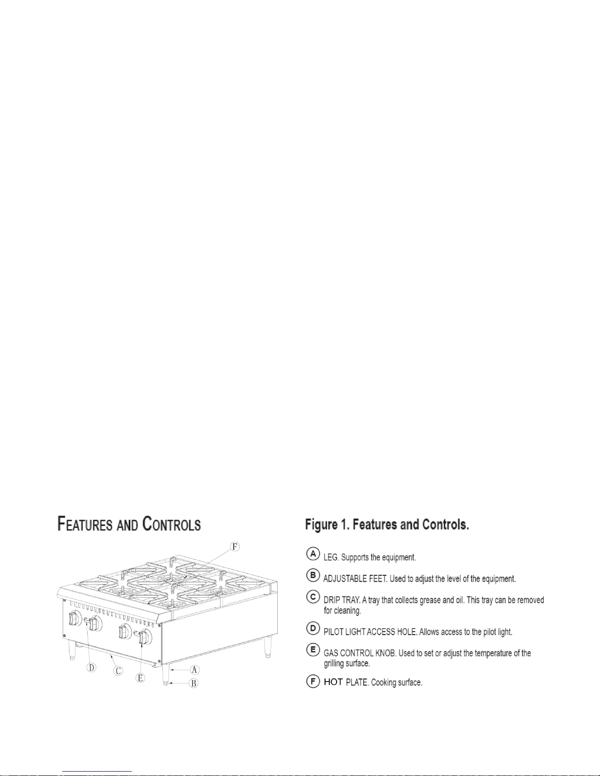
FEATURES AND CONTROLS:
 Loading...