

Paton MMA-160P, MMA-200P, MMA-250P Operation Manual

PATON VDI-SERIES PRO DC MMA/TIG/MIG/MAG
-1-

PATON VDI-SERIES PRO DC MMA/TIG/MIG/MAG
-2-
TABLE OF CONTENTS
1.
General information
6
1.1.
Technical characteristics
8
1.2.
Controls and connectors
10
2.
Setting the welding unit into operation
11
2.1.
Proper use
12
2.2.
Requirements for installation
12
2.3.
Connection to a power supply system
13
2.4.
Requirements for an electrical outlet
13
3.
Manual covered-electrode arc welding process (MMA)
13
3.1.
Preparing the welding unit for operation
13
3.2.
Operational cycle of the manual arc welding process
14
3.3.
Increased-current arc starting
15
3.4.
Reduced-voltage welding mode
16
3.5.
Protection against electrode sticking
17
3.6.
Setting the slope of the volt-ampere characteristic of the
welding unit
17
3.7.
Short arc welding mode
17
3.8.
Reduction of open-circuit voltage
17
3.9.
Welding at pulse welding current
18
4.
Argon arc welding process (TIG)
19
4.1.
Preparing the welding unit for operation
19
4.2.
. Operational cycle of the argon arc welding process with
TIG-LIFT function
20
4.3.
TIG-LIFT contact arc starting function
20
4.4.
Linear increase of welding current
21
4.5.
Welding at pulse welding current
21
5.
Semiautomatic arc welding process (MIG/MAG)
22
5.1.
Preparing the welding unit for operation
22
5.2.
Operational cycle of the semiautomatic arc welding process
24
5.3.
Welding at pulse welding voltage
24
6.
Setting the welding unit
25
6.1.
Switching to the required welding function
26
6.2.
Switching to the required welding process
26
6.3.
Return of the values of the functions and parameters of the
welding unit to the default factory values set for the current
welding process.
26

PATON VDI-SERIES PRO DC MMA/TIG/MIG/MAG
-3-
7.
Complete list of the welding unit functions and parameters
27
7.1.
Manual arc welding process (MMA)
27
7.2.
Argon shielded tungsten-arc welding process (TIG)
28
7.3.
Semiautomatic arc welding process (MIG/MAG)
28
8.
Operation with an electric generator
29
9.
Maintenance
29
10.
Storage
30
11.
Transportation
30
12.
Specification data
30
13.
Delivery set
31
14.
Warranty
31
15.
Information concerning disposal of equipment
33
16.
Safety instructions
35
17.
Electrical schematic diagram
36
18.
Acceptance certificate
37
PATON VDI-SERIES PRO DC MMA/TIG/MIG/MAG
-4-
DECLARATION OF CONFORMITY
Manufacturer:
„THE PILOT PLANT OF WELDING
EQUIPMENT OF THE INSTITUTE OF
ELECTRIC WELDING NAMED AFTER E.O.
PATON”
Address:
66 NOVOPIROGOVSKA STREET, KIEV CITY,
UKRAINE, ZIP-CODE 03045
Authorized
manufacturer's
representative:
MASTERWELD SP. Z O.O.
25, TADEUSZA BOYA – ŻELEŃSKIEGO
STREET, RZESZÓW CITY, POLAND, ZIP-CODE
35105
VAT: PL8133751525
I, the undersigned, declare under our sole responsibility that the
product listed below complies with the following Directives:
Product
DIGITAL INVERTER RECTIFIERS
Type:
PATON VDI – 160P, VDI – 200P. VDI – 250P
have been tested and conforms with the following specifications:
Directive
2014/30/EU
Electromagnetic
Compatibility
(EMC)
EN 60974-10: 2014-12
EN 61000-3-2: 2014-10
EN 61000-3-3: 2013-10
Directive
2014/35/EU
Low voltage
(LVD)
EN 60974-1: 2013-04
EN 62233:2008
Date 22/05/2017
Signed on behalf of the manufacturer by:
Vice President M. Olszewski
PATON VDI-SERIES PRO DC MMA/TIG/MIG/MAG
-5-
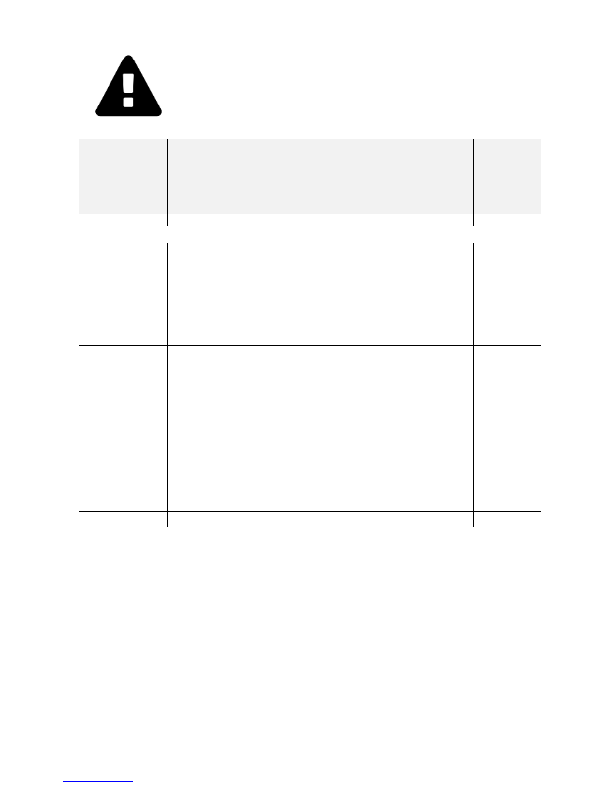
WARNING! When connecting the welding unit to the power
distribution board (at a temperature of 25 ºC), take into account throughthe-wall wiring and the lengths of extension cables.
Electrode
diameter for
a MMA
welding
process (mm)
Set current for
MMA and
TIG welding
processes (A)
Electrode wire
diameter for a
MIG/MAG
welding process
(mm)
Cross-section
area of the
power cable
conductor
(mm2)
Maximum
cable
length (m)
VDI-160P
Ф2 mm
Not more than
80
Not more than 0.6
1.0
75
1.5
115
2.0
155
2.5
195
4.0
310
6.0
465
Ф3 mm
Not more than
120
Not more than 0.8
1.5
75
2.0
105
2.5
130
4.0
205
6.0
310
Ф4 mm
Up to 160
Not more than 1.0
2.0
75
2.5
95
4.0
155
6.0
230

PATON VDI-SERIES PRO DC MMA/TIG/MIG/MAG
-6-
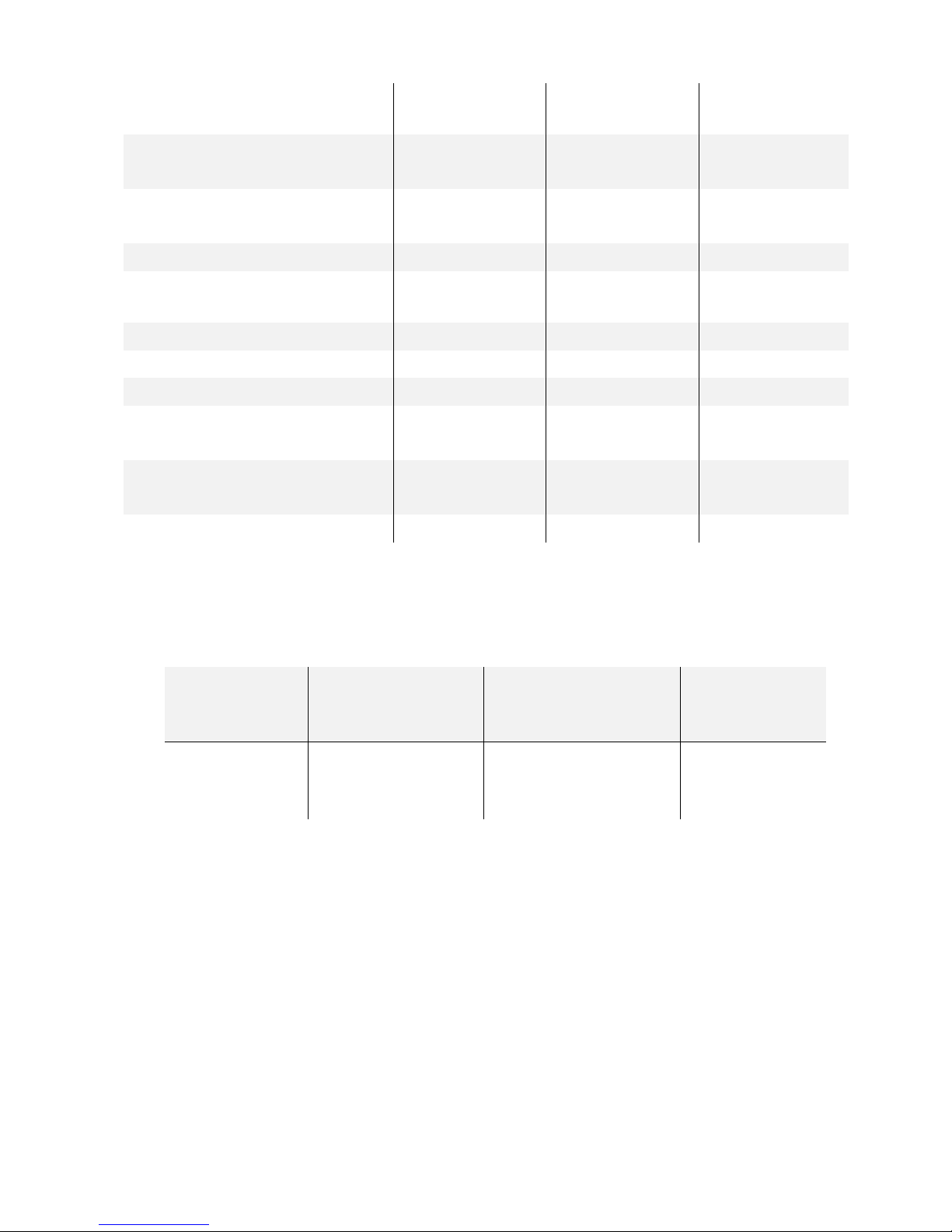
VDI-200P
Ф3 mm
Not more than
120
Not more than 0.8
1.5
75
2.0
105
2.5
130
4.0
205
6.0
310
Ф4 mm
Not more than
160
Not more than 1.0
2.0
75
2.5
95
4.0
155
6.0
230
Ф5 mm
Up to 200
Not more than 1.0
2.5
75
4.0
125
6.0
185
VDI-250P
Ф3 мм
Not more than
120
Not more than 0.8
1.5
75
2.0
105
2.5
130
4.0
205
6.0
310
Ф4 mm
Not more than
160
Not more than 1.0
2
75
2.5
95
4.0
155
6.0
230
Ф5 mm
Up to 250
Not more than 1.2
2.5
60
Ф 6 mm
for a free-
melting
electrode
4.0
100
6.0
150
1. GENERAL INFORMATION
The digitally controlled rectifier welding units PATON™ VDI-160P, VDI-200P,
and VDI-250P are designed for direct-current gas-shielded welding according to such
welding processes as a manual arc welding process (MMA), an argon arc welding process
(TIG), and a semiautomatic arc welding process (MIG/MAG) (with the welding unit
operating together with an external electrode wire feeding unit). The digital controller
used in these welding units ensures significant advantages for the welding unit as
compared with multifunctional analog controllers, as the analog controllers are designed

PATON VDI-SERIES PRO DC MMA/TIG/MIG/MAG
-7-
for the specific operating modes of controlled equipment and are not optimal in all
operating modes. The digital controller of the MMA welding units allows all the
capabilities of the welding unit, up to its capabilities at full power, to be used in all the
operating modes of the unit.
The MMA welding units pertain to the Professional Series equipment and are designed
for industrial use. The additional adjustment operations provided for the welding unit
make it possible to set the optimal values of the operating parameters of the unit in various
operating modes characterized by a high load factor at a rated current of up to 160 A, 200
A, or 250 A. The welding units can be used for manual arc welding with standard
electrodes 1.6 … 5 mm in diameter and free-melting electrodes up to 6.0 mm in diameter
and for semiautomatic arc welding with solid electrode wire 0.6 … 1.2 mm in diameter.
The function of reduction of open-circuit voltage in the manual arc welding process
(MMA), with the possibility for this function to be switched on and off, allows the
welding unit to be operated in unsafe environment.
The welding unit contains a module for protection against excess and low power
supply voltage.
Due to the increased frequency of the input voltage of the rectifier transformer of
the welding unit, the weight and overall dimensions of the transformer are significantly
reduced as compared with other welding units with similar characteristics.
The basic advantages of the PATON™ welding units are the following:
1. The possibility to adjust welding parameters in wide ranges
a) 1 basic parameter + 10 additional parameters for the manual arc welding process
(MMA)
b) 1 basic parameter + 4 additional parameters for the argon arc welding process
(TIG)
c) 1 basic parameter + 3 additional parameters for the semiautomatic arc welding
process (MIG/MAG)
2. The availability of the adjustable pulse welding mode for all the welding
processes.
3. The welding unit is protected against long-time fluctuations of power supply
voltage and ensures welding arc stabilization when the input voltage of the unit
changes in the range of 160 V through 260 V. It should be noted that welding
at a minimum voltage of 160 V is allowed only by using an electrode not more
than 3 mm in diameter for the manual arc welding process, or electrode wire
not more than 0.8 mm in diameter for the semiautomatic arc welding process.
4. The welding unit is rated for operation with a standard power supply system.
Due to the higher efficiency coefficient of the unit, the power consumed by
the unit is reduced by 50 percent as compared with other similar welding
units.
5. The rotation frequency of the driving motor of the ventilator of the welding unit
can be automatically varied depending on the temperature inside the unit.
This feature allows the service life of the ventilator and driving motor to be
increased and, additionally, dust content inside the unit to be reduced.

PATON VDI-SERIES PRO DC MMA/TIG/MIG/MAG
-8-
6. The welding unit is easy operated due to the optimal operating load factor in
operation at the rated current.
7. The enhanced reliability of the welding unit in operation in dusty environment.
8. The welding unit contains an electronic thermal protection system for
protecting all the heat-generating components of the welding unit against
overheating.
9. All the printed-circuit boards with electronic elements are impregnated with
two layers of high-quality varnish in order to provide the high reliability of
the welding unit within its service life.
10. Improved arc stability
1.1. TECHNICAL CHARACTERISTICS
PARAMETERS
VDI-160P
VDI-200P
VDI-250P
Rated power supply voltage
50/60 Hz, V
230
230
230
Rated power supply current, A
18 … 21
25 … 28
32 … 36
Rated welding current, A
160
200
250
Maximum operating current,
A
215
270
335
Operating load factor, %
70 % at 160 A
100 % at 134 A
70 % at 200 A
100 % at 167 A
70 % at 250 A
100 % at 208 A
Power supply voltage range, V
160 … 260
160 … 260
160 … 260
Welding current control range,
V
8 … 160
10 … 200
12 … 250
Welding voltage control
range, V
12 … 28
12 … 28
12 … 28
Diameter of a stick electrode,
mm
1.6 … 4.0
1.6 … 5.0
1.6 … 6.0
Diameter of electrode wire,
mm
0.6 … 1.0
0.6 … 1.0
0.6 … 1.2
Welding processes with a
pulse welding mode
MMA, TIG,
MIG/MAG
MMA, TIG,
MIG/MAG
MMA, TIG,
MIG/MAG
Increased-current arc starting
function of the manual arc
welding process
Adjustable
Adjustable
Adjustable
Reduced-voltage welding
function of the manual arc
welding process
Adjustable
Adjustable
Adjustable
Protection against electrode
sticking
Automatic
Automatic
Automatic
PATON VDI-SERIES PRO DC MMA/TIG/MIG/MAG
-9-
Reduction of open-circuit
voltage
ON/OFF
ON/OFF
ON/OFF
Open-circuit voltage in the
MMA process, V
12/70
12/70
12/70
Welding arc starting voltage,
V
110
110
110
Rated consumed power, kVA
4.0 … 4.6
5.5 … 6.1
6.9 … 7.7
Maximum consumed power,
kVA
5.0 … 6.2
6.6 … 8.0
8.5 … 11.0
Efficiency coefficient, %
92
92
92
Cooling
Forced
Forced
Forced
Operating temperature range
-25 … +45 ºC
-25 … +45 ºC
-25 … +45 ºC
Overall dimensions (length
width height), mm
325 245 250
325 245 250
325 245
250
Weight without the coil and
accessories, kg
5.4
5.6
5.7
Protection class*
IP 33
IP 33
IP 33
*These Professional Series welding units are protected against ingress of foreign particles more than
2.5 mm in size and against rain drops if the rain drops fall at an angle to the vertical surfaces of the
welding unit not more than 60 degrees.
The recommended lengths of the welding cables are indicated below.
Cable length
(m)
Maximum
current (A)
Cross-section area
of the cable
conductor (mm2)
Cable
designation
1 … 5
Not more than 160
16
KG 1 16
2 … 8
Not more than 200
25
KG 1 25
3 … 11
Up to 250
35
KG 1 35
PATON VDI-SERIES PRO DC MMA/TIG/MIG/MAG
-10-
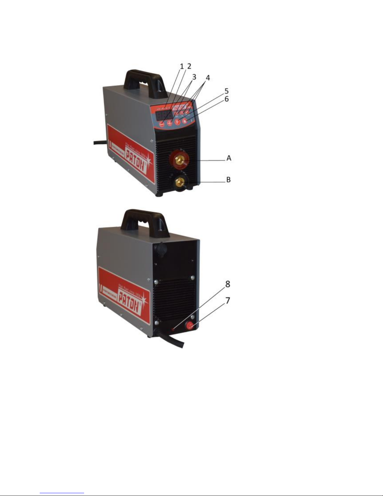
1.2. CONTROLS AND CONNECTORS
1.
Unit of measurement for the current displayed parameter:
a) V - volt
b) A - ampere
c) % - percent
d) s - second
2.
Digital seven-segment display
3.
Buttons for increasing or decreasing the selected parameter value
4.
Indicator of the current or selected welding process

PATON VDI-SERIES PRO DC MMA/TIG/MIG/MAG
-11-
5.
Button for selecting functions for the current welding process and for
switching to the required welding process:
a) Manual covered-electrode arc welding (MMA)
b) Argon arc welding with a no consumable electrode (TIG)
c) Gas-shielded semiautomatic arc welding (MIG/MAG)
6.
Indicator of the operating condition of the welding unit (can blink during
welding):
a) Continuously lights green when the welding unit is in the operating
mode and in the manual arc welding process.
b) Continuously lights yellow when the welding unit is in the standby mode
in the manual arc welding process or semiautomatic arc welding process.
c) Continuously lights red when a fault has occurred or the vending unit is
overheated in any operating mode.
d) Does not light when the power supply voltage is lower or higher than
the rated voltage.
A
(+)
The bayonet connector socket for connecting:
a) The electrode cable (or the grounding cable in some cases when special
electrodes are used for welding) for the manual arc welding process
(MMA)
b) Only the grounding cable for the argon arc welding process (TIG)
This connector socket is not used in the semiautomatic arc welding process
(MIG/MAG)
B (-)
The bayonet connector socket for connecting:
a) The grounding cable (or the electrode cable in some cases when special
electrodes are used for welding) for the manual arc welding process
(MMA)
b) Only the argon gas torch for the argon arc welding process (TIG)
c) The grounding cable for the semiautomatic arc welding process
(MIG/MAG)
7.
Push-button switch for switching on and off the welding unit
8.
Indicator of power supply voltage over 260 V (the indicator lights at the
instant of time when 260 V is exceeded)
2. SETTING THE WELDING UNIT INTO OPERATION
WARNING! Read Section 14, "Safety instructions", before setting the
welding unit into operation.

PATON VDI-SERIES PRO DC MMA/TIG/MIG/MAG
-12-
2.1. PROPER USE
The welding unit is designed for manual covered-electrode arc welding, argon arc
welding, and gas-shielded semiautomatic arc welding. Any other use of the welding unit
is considered as improper. The manufacturer of the welding unit is not responsible for
damages caused by any improper use of the unit.
The use of the welding unit is proper if all the requirements of this Operation Manual are
satisfied.
WARNING!!! Do not use the welding unit to unfreeze pipes.
2.2. REQUIREMENTS FOR INSTALLATION
The welding unit is protected against ingress of foreign particles more than 2.5 mm in
size. The welding unit is allowed for outdoor operation. The internal electrical and
electronic elements of the welding unit are protected against moisture but are not
protected against atmospheric condensate drops.
WARNING! After completing welding works in hot weather, or
completing intensive welding works in any weather, switch off the
welding unit only after at least 5 minutes of time required for the
electronic elements of the unit to be cooled.
WARNING! When operating the welding unit in cold season, after the
unit was switched off and cooled, condensate can be formed inside of the
unit, so switch on the welding unit only 3 … 4 hours after the switching
off.
For this reason, do not switch off the welding unit if it is anticipated that the unit is to be
switched on not later than 4 hours after the switching off.
Install the welding unit so as not to block or cover the ventilation slots on the front and
rear panels of the unit. Prevent ingress of metallic particles (for example, when grinding
the weld) sucked into the welding unit by the unit ventilator.
WARNING! After fall from a height, the welding unit might be a source
of electrical shock. Install the unit on a firm stable surface.
 Loading...