

Patol 5000, 5410 Series Manual
SERIES 5000
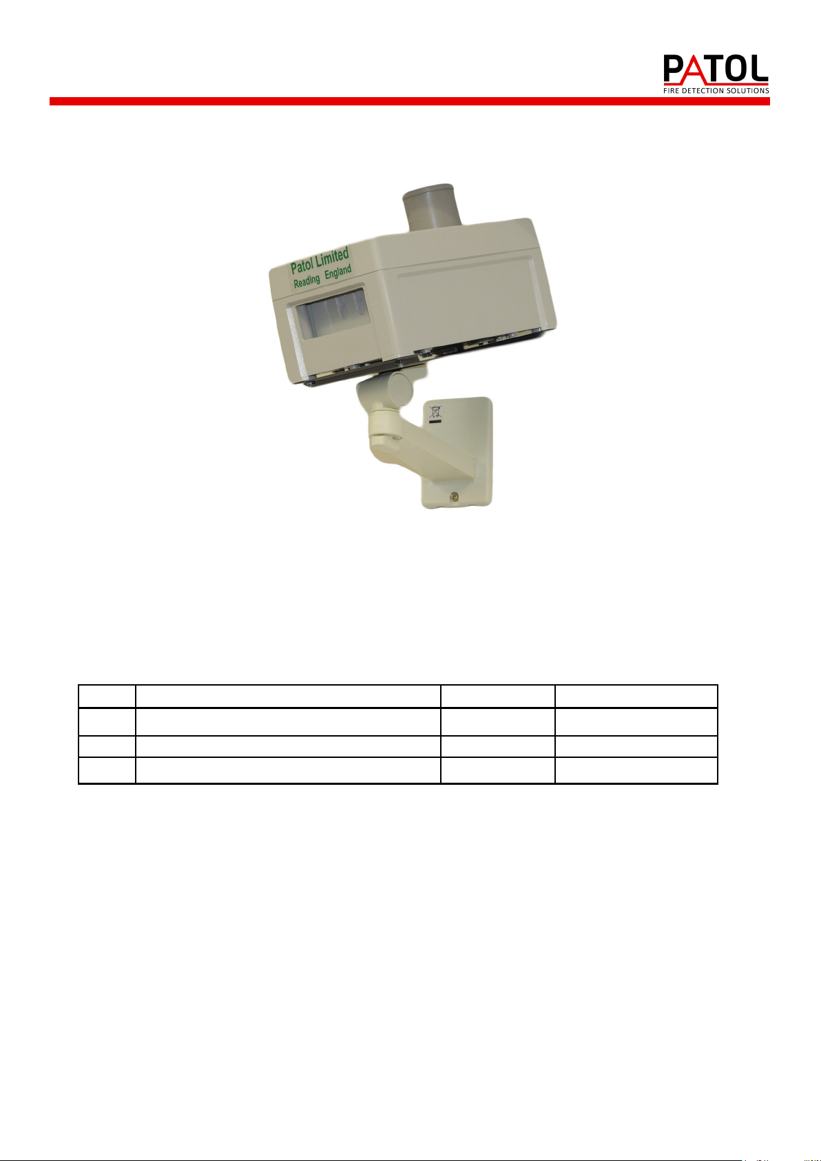
Model 5410 Infra-red Transit Heat Sensor
MANUAL
INSTALLATION - COMISSIONING
OPERATION - MAINTENANCE
Applicable to Unit Part Numbers 720-002 / 720-012
Serial Numbers 98538-01 onwards
Issue Change Date Remarks
1 Original 18/03/09 Based on D1140
2 Table 3 - reference corrected to D 15/11/12 Page 8
3 New document format 18/12/14
Contact Details:
Patol Limited
Archway House
Bath Road
Padworth, Reading
Berkshire
RG7 5HR
Tel: +44 (0)1189 701 701
Fax: +44 (0)1189 701 700
Email: info@patol.co.uk
Web: www.Patol.co.uk
1 D1145-3

SERIES 5000
1. INTRODUCTION
2. EQUIPMENT DETAIL
2.1 General Description
2.2 Relay Mode
2.3 Low Power Mode
2.4 Sensor Arrangement
2.5 Specification
2.6 Operational Programmability - SIL Switch
INDEX
1.1 General
1.2 Principles
2.7 Connections
3. INSTALLATION
3.1 Detection Coverage
3.2 Supply / Signal Cable
3.3 Purge Air Supply
4. COMMISSIONING
4.1 Cable Checks
4.2 Controller Set Up
4.3 Power Up Procedure
4.4 Purge Air Supply and Pressure Switch
4.5 Hot Body Simulation Tests
5. OPERATION
5.1 Normal
5.2 Alarm Condition
5.3 Reset
5.4 Fault Warning
5.5 Test
6. MAINTENANCE
6.1 General
6.2 Purge Air Filter
6.3 Fault Monitoring Functions
6.4 Infra-red Detection
2 D1145-3

1 2 3 4 5 6 7 8 9
200 C
320 C
SOLAR
o
o
10
Typical Black Bo dy Energy Em issions
5000 RESPONSE FILTER
WAVELENGTH (Micrometres)
SERIES 5000
1 INTRODUCTION
1.1 General
The Patol 5000 Series of equipment is specifically designed for the protection of establishments and
systems where a movement of materials with a potential fire hazard is a routine occurrence.
The 5410 Sensor employs enhanced Infra-red monitoring technology that enables the detection of fire
initiating materials, whilst they are being transported, and before they have reached a flame condition.
The system has many applications within industries such as Power Generation, Coal Mining, Process
Plant, Road Transportation and Rail Networks and has been specifically designed to both meet the rigors
of these environments and to provide the reliability required.
The equipment monitors for fire and fire potential of materials in transit. The system can detect anomalies
where combustion has not yet been reached, but where there is sufficient energy for a fire initiation upon
destination arrival.
A typical example is in the coal feed systems on power stations where coal on the ‘out field stack’ may
very well smoulder with little adverse effect for long periods of time. However, if imported to the power
station it may have devastating effects on conveyor systems, holding hoppers, blending plants etc.
Detection of hazards at temperatures below flame point including both embers and buried hot spots.
Air purged system for Dusty environments with air pressure monitoring.
Two wire operation - Powered by direct connection to standard fire trigger circuits or addressable
Patol remote controllers/interfaces available for two wire operation.
Volt free relay contact output operation selectable as standard.
Twin high integrity detection circuit channels for maximum reliability.
Unique reflective cone lensing system provides wide uniform coverage superior to some ember/spark
Coincidence - Double Knock - option for unit detector channels as standard.
Timed auto reset / coincidence analyser circuit.
Tuned response - solar blind.
High degree of ingress protection - IP66.
Specifically designed for high EMC compliance - CE Marked.
1.2 Principles
The principle of operation is that
temperature dependant black body
emissions occur for all materials.
These emissions range through the
infra red spectrum to visible light.
Both the wavelength and level of
peak energy emission are related to
temperature.
The 5410 Sensor are designed to
detect the changes in these
emissions that occur when a hot
body enters the field of view of the
detector.
By the use of both optical filtering and electronic analysis of the various parameters the system is blind to
visible light from the sun or local luminaires, whilst being able to detect relatively low temperature material
moving through the field of view.
loop interfaces - Signalling mode user configurable to simulate smoke & heat detector protocols.
detectors.
Fig. 1
3 D1145-3
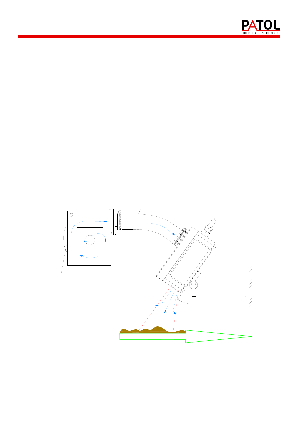
MONITORED MATERIAL
UP TO 2m
0° TO 55°
SENSOR
SIGNAL/SUPPLY CABLE
AIR
AIR FILTER
AIR PURGE UNIT
110/230Vac
AIR HOSE
SERIES 5000
EQUIPMENT DETAIL
2.1 General Description
The 5000 Series system described here comprises two primary elements :-
Sensor Unit - Model 5410
Air Supply / Blower Unit
The Sensor is located above the materials transit path (e.g. conveyor) by means of the adjustable
mounting bracket and aligned such that the monitored hazard passes through the unit’s field of view. The
height and angle of the sensor determine the width of the monitored path.
The 5410 Sensor outer case is equipped with an air hose spigot for connection of an air supply. This is
required such that a positive air pressure is maintained around the inner module sensor “windows”.
There is a continuous air flow from the outer case optical path aperture which stops dust settling on the
inner sensor module. Also, by maintaining a positive pressure within the enclosure, ingress of explosive
gas or dust is prevented. The arrangement can permit the unit to be employed in a Hazardous Area
depending on applicable local regulations.
The air purging is essential in dusty environments such as coal conveyors, and is recommended in even
relatively clean applications. A series 5000 air purge blower and filter unit is employed when an ‘on site’
air supply is not available. (See section 2.7)
A pressure switch is located within the unit to monitor the purge air and signals a loss of pressure as a
Fault
Fig. 2
The unit may be user selected to either of two principal operating settings which are referenced as :-
“Relay Mode” - Operation from a 20 to 30 Vdc supply.
“Low Power Mode” - Operation from a fire alarm trigger circuit / addressable loop.
A description of these arrangements is provided in sections 2.2 and 2.3 following.
4 D1145-3
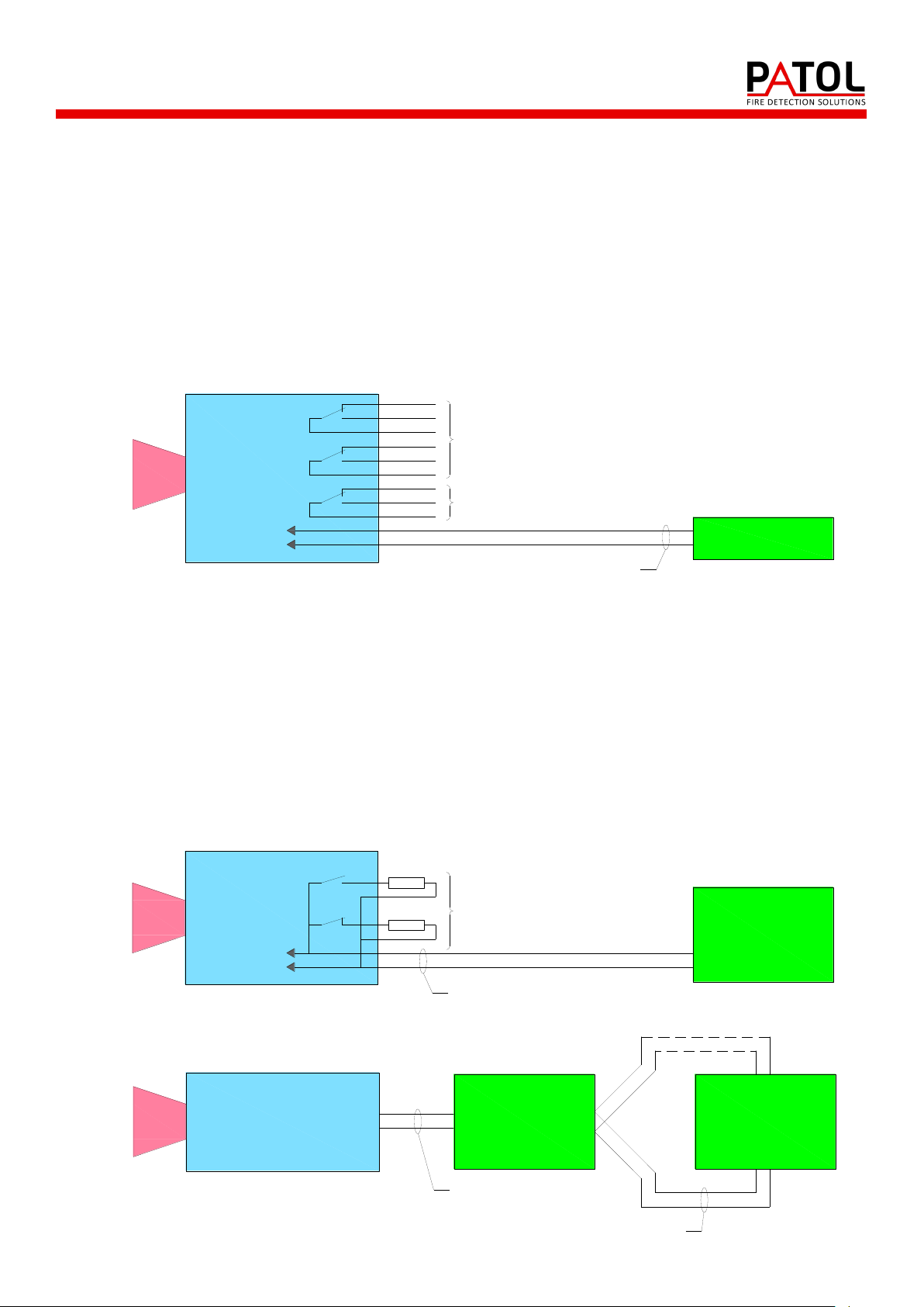
ADDRESSABLE
LOOP INTERFACE
MODULE
ANALOGUE
ADDRESSABLE
FIRE ALARM
CONTROL PANEL
2 WIRE CONNECTION
ALARM & EOL
RESISTOR
CONFIGURATION
AS PER FIG. 2
2 WIRE ADDRESS LOOP
ALARM AND EOL
RESISTOR AS PER
FIRE PANEL
REQUIREMENTS
ALARM
FAULT
SUPPLY
CONVENTIONAL
FIRE CONTROL
PANEL AND/OR
PATOL SIGNAL
RELAY MODULE
2 WIRE TRIGGER CIRCUIT
SOLID STATE OUTPUT SWITCHES
*
*
FIRE RELAY
(NORMALLY DE-ENERGISED)
FAULT RELAY
(NORMALLY ENERGISED)
TRIP
ALARM
FAULT
SUPPLY
24Vcd
POWER SUPPLY
2 WIRE SUPPLY CIRCUIT
VOLT FREE CONTACTS
SERIES 5000
2.2 Relay Mode
The unit is equipped with relays which are enabled in this mode.
A 24 Vdc (nom) supply is required to operate the unit (max current 24mA).
The unit’s volt free relay contacts are used for signalling of Fire and Fault conditions.
The Fire relay is normally de-energised and energises on an infra-red detection alarm.
The Fault relay is normally energised and de-energises on power supply removal, module regulation failure
or loss of purge air.
Refer to figure 3.
5410 SENSOR HEAD
Fig. 3
2.3 Low Power Mode
In this mode the relays are disabled and the unit’s quiescent supply current is very low and of a similar
level to conventional Smoke and Heat detectors.
By the connection of appropriate resistor values to the sensor’s “solid state” outputs the unit will signal
Normal, Fire & Fault conditions by line current levels, in a manner that permits the unit to be connected
directly to fire control panels via alarm trigger circuits, or to the monitored inputs of addressable loop
interface modules.
The unit can also be employed with the two wire connection to a remote Patol signal relay module.
Refer to figures 4 & 5.
5410 SENSOR HEAD
Fig. 4
5410 SENSOR HEAD
5 D1145-3
Fig. 5
 Loading...