

4247-A
Voice Synthsizer
Instruction Manual
[ TYPE : BDV ]
Thank you very much for purchasing the Voice Synthsizer. Before use, please read this
Instruction Manual thoroughly and use the productcorrectly.In addition,
keep this manual in a safe place.When carrying out maintenance/check, repair etc. , be sure to
reread this manual.If an unclear point arises, please inquire to each sales office or technical
consultation service written in the last page.
Safety Precautions
In order to prevent harm on users or other persons and damage on properties, the matters to
be kept without fail are explained as follows.
■The degree of harm and damage that will occur when misuse is made by ignoring
the contents of indication is classified and explained by the following indications.
WARNING
CAUTION
1.Matters to be kept without fail for Safety Purpose
WARNING
●At the wiring and mounting of products, be sure to cut off power source.There is a risk
of electrical shock.
●Do not disassemble or modify the product.There is a risk of fire, electrical shock etc.
For repair, check etc of inside the product, please inquire to each sales office or
technical consultation service written in the last page.
●Pay attention not to mistake wiring work.If wiring is mistaken,the internal
circuit may burn out and it will become a cause of fire.
●Be sure to use the power supply within the allowable voltage range of the
product.Otherwise,it may become a cause of fire and/or failure.
●For the installation with execution of work,be sure to ask a professional
company.Otherwise,there is a risk of electrical shock,fire and/or falling etc.
CAUTION
●Be sure to connect the external fuse for protection of the power supply
circuit and internal circuit of the product.
●
Do not use it at the place where vibration exists that is exceeding the specifications.
In addition,be sure to install on upright direction at the place where
vibration exists.There is a risk of damage and/or falling of the product.
The trouble occurred due to mishandling against the warning and caution matters, and/or
due to disassembling, modification, natural disaster etc. cannot be guaranteed. Further,
avoid the usage under conditions other than the contents described in this manual.
Request
●Use it in the environment where strong radio waves and/or inductive noise
do not exist.Otherwise,there is a risk of noise generation from the Speaker.
●Use it in the environment where corrosive gas does not exist. Otherwise,
it will become a cause of failure.
●In order to avoid electrostatic breakdown,start to work after discharging static electricity
which is charged on a human body.
By touching an earthed metallic part with a bare hand, static electricity can be discharged.
●Perform fitting of each part at a recommended torque value.
●Pay attention not to lose the parts such as the terminal covers,front covers etc.
which are to be detached at performing work.
●If this product is used for the safety-sensitive security purpose, be sure to perform daily
check, and establish the system design that can cope with the occurrence of accidental
trouble and failure.
~Caution on copyright~
If a work that was recorded or copied from music CDs or other media is used at public
places,law enforcement for copyright infringement may be imposed. When using a work
that was recorded or copied from music CDs or other media, be sure to obtain permission
from the author.In addition,the copyright of audio/music data which are distributed or sold
by PATLITE Corporation belongs to PATLITE.
It is strictly prohibited to copy/reprint the partial or whole contents of audio/music data of
PATLITE Corporation or to transfer/sell them on computer networks etc. without the
permission of the right holder.
2.Indication Method of Models
The column with this indication shows the contents in which "possibility
of death or being seriously injured is assumed."
The column with this indication shows the contents in which "possibility
of being injured or only occurrence of property damage is assumed."
BDV - 15 K F - J
■Rated voltage
J: 12-24V DC
K: 100V/220V AC
■Body color
J :Light gray
K :Dark gray
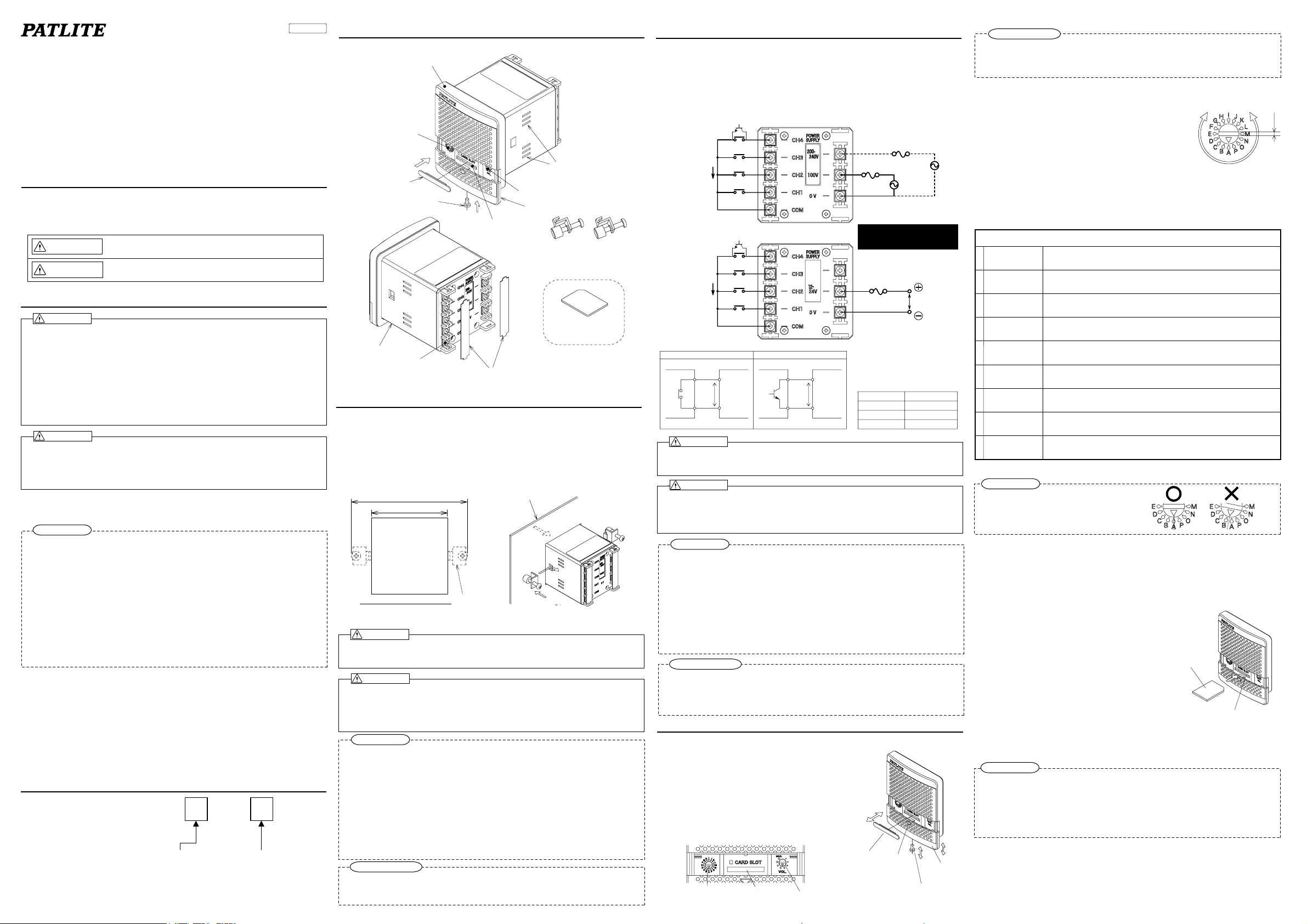
3. Parts Names
【Front side】
Front panel
Operation mode
switch
Waterproofing rubber
【Rear side】
Case
Terminal block
(Screw M3×6)
for the slot
Mounting screw for
front cover(M3X6)
Card slot
Terminal cover
Air hole
Volume
Front cover
Mounting angle
(Accessory)
SD Card
Model:SDV-128P
(sold separately)
※PATLITE corporation is a member of
the SD card Association.
4. How to install
Install the product according to the procedure below.
①Create mounting holes on a mounting surface (board thickness: 1mm - 10mm) where there
is enough space for the mounting angle. (See the mounting dimensions diagram)
②(a)Insert the product from the front of the mounting surface.
(b)Attach the mounting angle which comes with the product to the holes on the side of the product.
(c
)Then fasten the screws of the mounting angle. (Recommended tightening torque: 0.7±0.1N・m)
③Confirm that the product and the mounting angles are installed properly.
Mounting surface
(104mm)
+0.7
0
□68 mm
Mounting dimensions diagram
※The installation hole size
conforms to IEC-61554(DIN-43700).
WARNING
●
At the mounting of products, be sure to cut off power source. There is a risk of electrical shock.
●For the installation with execution of work, be sure to ask a professional
Otherwise, there is a risk of electrical shock, fire and/or falling etc.
CAUTION
●Choose a location for the mounting surface where it has enough strength to support the
weight of the product, and where there is less vibration. In addition, do not use as a
vehicle. Failure to do so may be the cause of injury or damage to the product.
●Be sure to use both pieces of mounting angle, and fasten them with the recommended
tightening torque. Failure to do so may be the cause of injury or damage to the product.
Request
●Secure a enough space in which the mounting angle can also be installed when choosing
a mounting surface.
●Install the product on a flat surface without bumps and dips. Failure to do so may weak
its resistance to water and dust.
●To prevent the product from falling in places where vibration may be generated,
applthread locking adhesive or the like, and perform periodic checking of the tightness of
the mounting angle.
●I When mounting it at a high place, choose the place where a foothold exists for facilitating
repair work.
●If it is used under the connected state to the power supply, then provide a switch which
can easily cut off power supply in proximity to the product, for the safety purpose.
●Please install it not to close the air hole.
Other Precautions
●The clamp face might resonate by the material, the thickness of the clamp face, and the
reproduction volume of the product, and the vibration sound be generated. Measures can be
done by reinforcing the clamp face.
(board thickness:1mm~10mm)
Mounting
angle
(a)
(b)
(c)
company.
5. How to perform wiring
Before wiring the product remove the terminal cover. And after the completion of the wiring
attach the terminal cover.
●For the external contact of signal line, use no-Voltage contact circuit such as relay switch
or open collector circuit(NPN type). As for the contact capacity,see the table below.
●The terminal screws should be fastened with the recommended tightening torque (0.3N・m)
■Wiring examples
●BDV-15KF
●BDV-15JF
Chart1.Specifications of Signal line
No-voltage contact curcuit
External point of contact External point of contact
Wiring when NPN
transistor is used
CH4
CH3
CH2
CH1
COM
Wiring when NPN
transistor is used
CH4
CH3
CH2
CH1
COM
NPN open collector curcuit
BDV
7mA
←
Signal line
15V 15V
COM
7mA
←
BDV
Signal line
COM
Fuse
250V 0.5A
Fuse
125V 0.5A
※Do not connect the power sources
od 100V and 220V simultaneously
220V AC
100V AC
Do not supply a voltage for the signal line.
Failure to do so may be damaged to the product.
No use
Fuse
125V 0.5A
Chart2. Contact Capacity
Current capacity
Withstand Voltage
Leakage current
ON voltage(Vsat)
12-24V DC
10mA or more
20V DC or more
0.1mA or less
1V or less
WARNING
At the wiring of products, be sure to cut off power source. There is a risk of electrical shock.
●
●Pay attention not to mistake wiring work. If wiring is mistaken,the internal circuit may
burn out and it will become a cause of fire.
CAUTION
●Be sure to connect the external fuse for protection of the power supply circuit and
internal circuit of the product.
●The terminal screws should be fastened with the recommended tightening torque
(0.3N・m). Otherwise, there is a risk of damage by short-curcuit, after wiring comes off.
Request
●Before switching on the power supply, confirm that the wiring is correctly performed.
●For countermeasure of noise, it is recommended to perform wiring as short as possible,
and to use shielded wires. In addition, if a signal line is passing along high voltage cables
or its wiring is located at the place likely to receive induction noise, there is a risk of
malfunction by the effect of noise.
●If a no-voltage contact such as a relay or a switch etc. is used for power supply line,
select the contact for which rush current is considered. If capacity is insufficie nt, it will
become a cause of welding (deposition) of the contact and/or malfunction.
●The use of M3 ring terminals with insulating coating is recommended for the wiring of
terminal block to prevent disconnection of wires. Recommended product: N1.25-3
(Product confirming to RoHS)
Other Precautions
●If power supply or signal lines are switched on simultaneously at the use of plural units,
a shift of playing the voice period will occur.
●BDV-15JF comes to receive the influence of the noise easily if you connect
the 0V terminal to the terminal COM.
6.How to use the product
6-1. Opening and closing the front cover
Open or close the front cover according to the procedure
shown below when performing tasks such as adjusting the
volume of the voice or selecting the mode switch.
①Remove the mounting screw (M3×6) for the front cover.
②Push the lower front cover section (Part A in the figure
on the right) lightly with finger to slide it downward.
③When a SD card is to be used,remove the waterproof
packing for the slot.
④After completing tasks, attach the parts removed in
the procedure from ➀ to ➂ in the opposite order.
(Recommended tightening torque: 0.3N・m)
Operation
mode switch
Card slot
Waterproof packing
Volume
Part A
Front cover
+Screw(M3X6)
Other Precautions
●Attach the waterproof packing for the slot securely. Failure to do so may weaken the product's
resistance to water and dust.
●Fasten +screw for front cover with the recommended tightening torque.
●Please do not lose detached parts.
6-2.Selecting play mode
By operating mode switch, one of the play modes shown below can be selected.
[factory default setting]
The message is registered to No.4 or earlier:A
The message is registered to No.5 or later:B
Use a flat-blade screwdriver with the blade
thickness of 1.0mm or thinner for turning the switch.
□how to select the play mode
①Change the operation mode switch to the play mode you want to use.
When you select the mode I,J,K,L,M,N,O and P,The play mode is test mode.
②Reactivate the product.(It is also possible to reboot from the front side
of the product with the SD card.When the SD card is inserted,the information
sound is playing.Afterwards,when the information sound is playing again,
the mode has been changed.)
③Confirm the message of each CH is playing, and the play mode was changed.
Play mode(Setting with operation mode switch)
A
Bit input mode
B
Binary input mode
Bit input
C
sound redution mode
Binary input
D
sound redution mode
Bit input
Latest input
E
priority play mode
Binary input
Latest input
F
priority play mode
Bit input
G
Hold play mode
Binary input
H
Hold play mode
I
~
Test mode
P
* Refer to“6.5 How to Play Messages”About the operation of each mode.
CH input : CH1 - CH5 / Number of playing messages : 5
CH input : CH1 - CH5 / Number of playing messages : 31
CH input : CH1 - CH4 / Number of playing messages : 4
CH5 : Input reduces the volume by 15dB.
CH input : CH1 - CH4 / Number of playing messages : 15
CH5 : Input reduces the volume by 15dB.
CH input : CH1 - CH5 Number of playing messages : 5
When the next message is input while message is being play, the message that is being
played is stopped and the latest input message is playing.
CH input : CH1 - CH5 Number of playing messages : 31
When the next message is input while message is being play, the message that is being
played is stopped and the latest input message is playing.
CH input : CH1 - CH5 Number of playing messages : 5
Message play is possible only while the input is held.
The play stops when the input stops.
CH input : CH1 - CH5 Number of playing messages : 31
Message play is possible only while the input is held.
The play stops when the input stops.
The message No.1 plays.
Request
●Make sure that there is no misalignment with the
operation mode switch when selecting.
If there is misalignment as shown in the figure
on the right, the play mode selected may not play.
6-3.Rewriting the Message
By using an SD card (Model: SDV-128P Sold separately), and a sound writing tool (Model:
FV-Win Sold separately), and a patlite playlist editor,the message can be rewritten.
The maximum length of time for this product is a total of 63 seconds (in case of 64kbit/s,
Fs=44.1kHz / internal memory size 508KB).For the method of creating data and storing it on
an SD card, see the instruction manual for the sound writing tool.
Message rewriting procedure
①Turn on the power of the product,
Comfirm neither COM nor CH are short-circuited.
※The message rewriting cannot be done while the
voice is playing or the test is playing.
②After opening the front cover and Inserting the
SD card which be rewritten the playlist and message data,
Playing the infomation sound ”PIPO” and Rewriting is begun.
③When the rewriting is completed and information
sound “PI”, Remove the SD card.
*Rewriting should be completed within 60 seconds. When playing the
information sound other than the above,or when no response, the
rewriting is not successfully completed.
See Section “8. Before You Request a Repair.”Moreover, when the
volume has been minimized, the information sound is not heard.
SD Card
Card slot
Request
●For the SD card, use type SDV-128P sold separately. Operation is not guaranteed if an
SD card of any other type is used.
●When formatting the SD card, do it in either of FAT16.
●When inserting the SD card into the card slot, pay attention to the orientation of the SD
card. And do not forcibly insert the SD card into the card slot. Doing so may cause
damage to the product and the SD card.
●Please note that the foreign body doesn't enter the card slot.
1mm
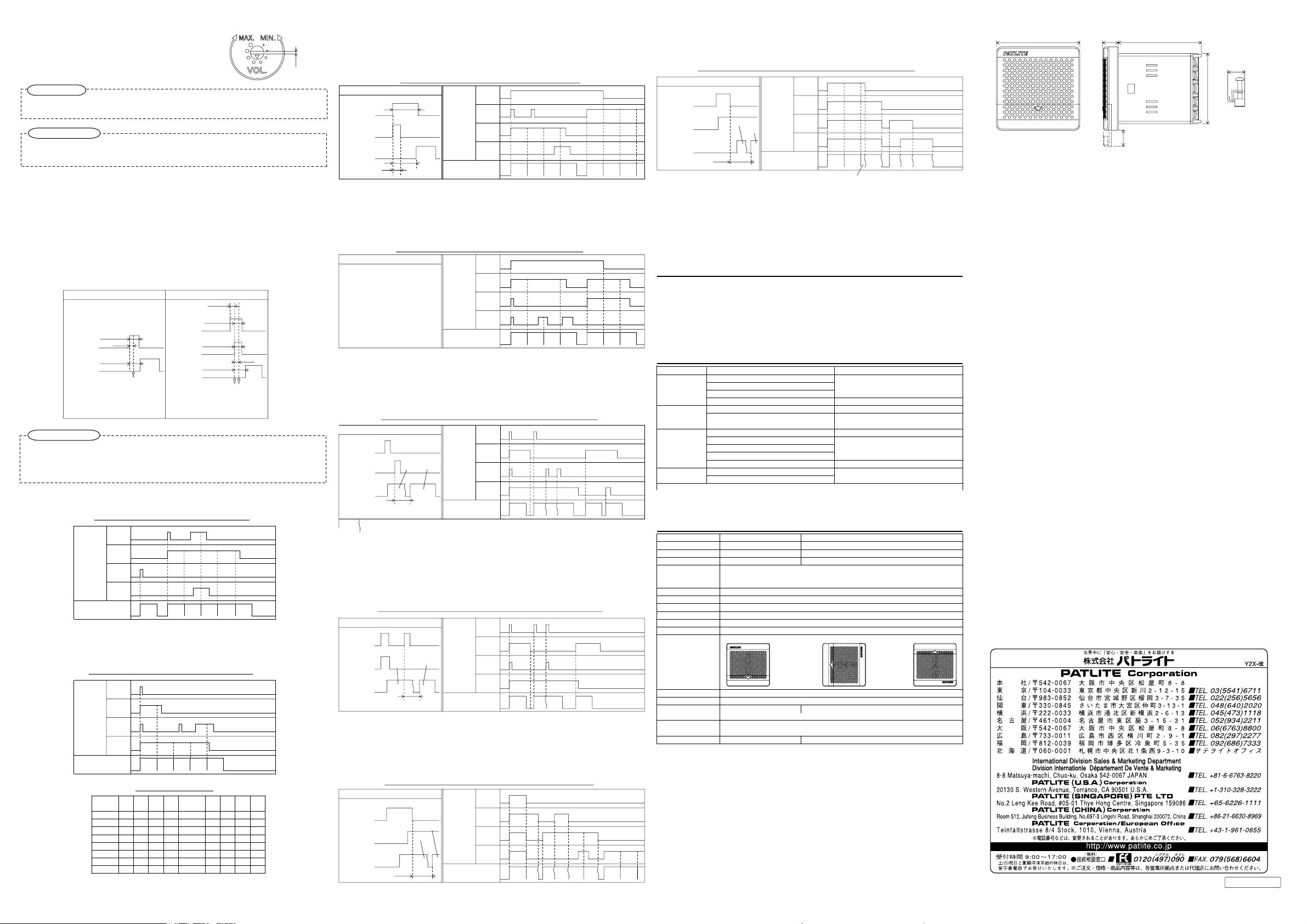
6-4.Adjusting the volume
Volume can be adjusted using the volume control.
Volume
larger
Volume
smaller
Use a flat-blade screwdriver with the blade
thickness of 1.0mm or thinner for turing the
Volume control.
1mm
Request
●Turn the volume control lightly. It may be damaged if a torque of 0.3N・m or higher
is applied.
Other Precautions
●When the volume becomes louder,the sound may be distorted in some messages.
In some usage environments, the volume may not be zero even if the volume control is
●
set to minimum.
6-5.How to Play Messages
When the common line and one of the signal lines is short-circuited after turning on the power.
・Playing the masseage once by the short-circuited of 100ms or more(Pulse input).
・When this product is operated by the power supply start, about 500ms is
necessary from the turning on the power to the playing of the sound.
・All modes are common to timing from the CH input to the playing of the sound.
Please refer to the table below for operation.
・In case there are two or more of CH1 - CH4 and the common line are short circuited,
the message of a CH with a larger Number is played (bit input only).
Signal entry priority order : CH4>CH3>CH2>CH1
Timing CH input of bit input
Holding time
100ms or more
CH input
Sound play
After input is established,Any CH input is not
accepted until the play ends of sound.
100ms
Time lag
About 300ms
Input is established
Timing CH input of binary input
within 5ms
Holding time
100ms or more
CH input2
Holding time
100ms or more
CH input1
Sound play
Ch input of binary input within 5mm, Holding
100ms or more.
After input is established,Any CH input is not
accepted until the play ends of sound.
Time lag
About 300ms
Binary input
is established
100ms
Input is established
Other Precautions
●It is not a breakdown though a pop noise might be generated at change the power on/off
and start of playing.
●Even when some products are started at the same time, the gap is caused in the playing
of the message.
6-5-1.Bit input mode (
Play sound of selected CH,when short-curcuited common line and CH1~4 line.
6-5-2.Binary input mode(
Play sound of selected binary code,when short-curcuited common line and CH1~4 line.
(Refet to binary code table)
※the”1”in the table refers to the short-circuit between the signal line and the common line.
operation mode switch
Timing chart table of bit input
CH4
CH3
Input CH
CH2
CH1
Message No.
operation mode switch
Timing Chart table of binary input
CH4
Input CH
CH3
CH2
CH1
Message No.
Message
CH1 CH2 CH3 CH4
No.
11000
20100
31100
40010
51010
60110
71110
80001
:A)
No.2 No.4 No.3 No.4 No.3 No.3
:B)
No.15 No.5 No.1 No.1 No.3
Binary code table
Message
CH1 CH2 CH3 CH4
No.
91001
10 0101
11 1101
12
13
14
15
0
0
0
1
1
0
1
1
1
1
1
1
1
1
1
1
6-5-3.Bit input・sound redution mode (
operation mode switch
:C)
CH1~3:Bit input/ CH4 Input reduces the volume by 10dB.
・When playing message have some phrase,Next phrase is reduced.
・According to the playlist,it is redused on the way of the phrase.
・There is no priority level in CH4.
Timing chart table of bit input・sound redution
Timing of input
300ms
CH4 input
(sound redution)
or more
Input CH
CH input
Sound play
100ms or more
300ms
sound
redution
6-5-4.Binary input・sound redution mode (
CH4
sound
redution
CH3
CH2
CH1
Message No.
sound
sound
redution
No.2
redution
No.2
sound
redution
No.2
sound
redution
No.3
operation mode switch
:D)
CH1~3:Bit input/ CH4 Input reduces the volume by 10dB.
・When playing message have some phrase,Next phrase is reduced.
・According to the playlist,it is redused on the way of the phrase.
Timing chart table of binary input・sound redution
Timing of input
CH4
sound
redution
CH3
Ref.6-5-3 binary input・sound
redution mode
Input CH
CH2
CH1
sound
sound
sound
Message No.
6-5-5.
Bit input・Latest input priority play mode
redution
No.7
(
operation mode switch
redution
No.4
redution
No.5
sound
redution
No.4
:E)
CH1~4:Bit input
・When the next message is input while message is being play, the message
that is being played is stopped and the latest input message is playing.
・The play of the message ends by one time even if it keeps holding the input.
Timing chart table of bit input・latest input priority play
Timing of input
CH2 Input
CH1 Input
Sound play
No.2 No.1
600ms or less
Input CH
CH4
CH3
CH2
CH1
Message No.
No.4 No.4
No.2
No.2 No.3 No.1
[ ] means the message is interrupted
6-5-6.
Binary input・Latest input priority play mode
CH1~4:Binary input
・When the next message is input while message is being play, the message
that is being played is stopped and the latest input message is playing.
・The play of the message ends by one time even if it keeps holding the input.
Timing chart table of binary input・latest input priority play
Timing of input
CH2 Input
CH1 Input
No.3
Sound play
600ms or less
6-5-7.Bit input hold play mode(
CH input : CH1 - CH4
・Message play is possible only while the input is held.
・The play is stopped when the input is lost.
Timing of input
CH2 Input
CH1 Input
Sound play
600ms or less
Input CH
No.2
Message No.
operation mode switch
Timing chart table of bit input・hold play mode
No.1
CH input
No.2
Message No.
(
operation mode switch
CH4
CH3
CH2
CH1
No.15 No.8 No.10 No.4
:G)
CH4
CH3
CH2
CH1
No.4 No.3 No.2 No.2 No.2No.3 No.1 No.1
:F)
sound
redution
No.3
sound
redution
No.6
No.3
No.3
No.6 No.6
6-5-8.Binary input hold play mode (
operation mode switch
:H)
CH input : CH1 - CH4
・Message play is possible only while the input is held.
・The play is stopped when the input is lost.
Timing chart table of binary input・hold play mode
Timing of input
CH2 Input
Input CH
CH1 Input
No.3
No.1
Sound play
600ms or less
6-5-9.Test play(
The sound of CH1 keeps playing.While playing the sound,Any CH input is not accepted.
operation mode switch
CH4
CH3
CH2
CH1
Message No.
:I~P)
No.15 No.2No.15
No.15
No.7 No.3 No.1
Use it when you confirming the operation and adjusting the volume.
・When the product is rebooted in test play mode,Operation mode is changed
to "A" when you return the operation switch.Insert the SD card in the card
slot or reboot, when you change excluding “A”.
7. Options
■SD card Model:SDV-128P
It is SD card for the sound and the voice product. When the message is
changed,it uses.
■Voice writing tool Model:FV-Win
The voice writing tool and 2000 kinds of MP3 standard message are collected.
8. Before you request a repair
Symptom Points to be a checked How to recover (Reference item)
No sound is played
It plays a different CH
Rewriting the sound is
not possible
The SD card is not
●If the product does not operate correctly even after it is properly installed and handled,
contact a branch office or the technical support printed on the last page. 。
Is the power supplied?
Are the common terminal and the CH terminal short-circuited correctly?
Is not STOP input?
Is the volume control not set to the minimum?
Are the common terminal and the CH terminal short-circuited correctly?
Is the operational mode switch switch correctly
set?
Is the power supplied?
Is the playlist made in the SD card?
Are the folder/file name, the content of the playlist folder/file correct?
Is the data correctly stored in the SD card?
Is the volume control not set to the minimum?
Do you use“SDV-128P?
read.
Is the SD card correctly inserted?
Comfirm the wiring.(5.How to perform wiring)
Adjusting the volume(6-4.Adjusting the volume)
Comfirm the wiring.(5.How to perform wiring)
Comfirm the operation mode switch or reboot
the product. (6-2.Selecting play mode)
Comfirm the wiring.(5.How to perform wiring)
Confirm playlist and data folder in the SD card.
(FV-Win help file)
Adjusting the volume(6-4.Adjusting the volume)
Confirm the SD card.
(6-3.Rewriting the message)
9. Specifications
Model
Rated voltage
Voltage range
Power consumption
Sound Pressure Level
Voice file
File format
Internal memory size
Number of playing message
Operating temperature range
Relative humidity
Mounting direction
Protection rating
Insulation resistance
Withstand voltage
Vibration resistance
Mass
BDV-15JF BDV-15KF
12 - 24V DC 100V / 220V AC(50/60Hz)
10.8 - 26.4V DC 100V ±10% AC/ 220V ± 10% AC
Max.4W Max.5W
M
ax. 87 dB : Condition for determination:Fit the product on the plate of □300mm, and measure the level with the 1kHz sine
Indoor:Normal and reverse direction are possible. (When it might be splashed with water,use the normal direction) Outdoor: Normal direction
wave at the distance of 1m from the center the product,in the front direction.
volume adjustable
MPEG1-Audio Layer Ⅲ(MP3) Standard bit rate:64kbit/s、Fs=44.1kHz
508KB(Total of MP3 data)/Maximum playing time 63sec (At playing of the standard bit rate data)
1MΩ or more ( at 500V DC ) between current-carrying and non-current-carrying part
500V AC (1 minute) 1500V AC (1 minute)
30Hz cross direction:2h/Horizontal direction:2h/Vertical direction:2h
※The sound pressure lebel may be lower depending on the Sound, usage environment, and supplied voltage.
FAT16
Bit input:4 / Binary input:15
2
-10 ~ 50℃
←Lateral
direction
340g ±10%220g ±10%
Reverse
direction→
85%RH or less (without the dew condensation)
←Normal
direction
IP54(Normal direction panel mounting only)
( between current-carrying and non-current-carrying part )
19.6m/s (Normal direction mounting )
【Outline dimensional drawing】(mm)
□80
15.2
79.5
Length in which front cover
can be moved
15.5
□67.5
Mounting angle
●Please note that will not be held responsible for the failure or damage caused
by handling the product in ways not observing the warnings or cautions contained
in this document.
●Please note also that the contents in this document may be changed for improvement
without notification in advance.
17.2
(Accessory)
4247-A
 Loading...