

Page 1
-6-
Type : LU7
Signal Tower
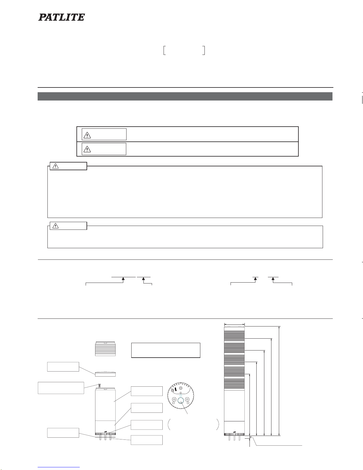
2. Model No. configuration
3. Parts name and Dimensions
INSTALLATION MANUAL
LU7-□□FB
LU7-E-□
■LED color
R:Red
A:Amber
G:Green
B:Blue
C:White
■LED unit
■Rated voltage
02:24V DC
M2:90~250V AC
■Light method
FB:Continuous light or flashing,
with buzzer
Nothing:Continuous light
〔Base unit〕
〔LED unit〕
( Unit:mm )
Volume
1 Light 211
(
10
)
2 Lights 252
3 Lights 293
4 Lights 334
5 Lights 375
φ70
Head cover
< LED unit >
< Base unit >
Waterproof sheet
■Parts name
■Dimension
VOL.
Terminal block
Body
Panel board maximum
installable thickness : 10
Thank you for specifying the PATLITE Signal Tower for your application. Please read these instructions carefully before
you perform installation, maintenance and repair. Store this manual carefully for easy reference. If you have any
questions about this product, please contact PATLITE Corporation.
1. To operate this product safely, please observe the following
● Make sure the power is OFF before wiring. Wrong wiring may result in a cause of short circuit or electric shock.
● Make sure the power is OFF to avoid an electric shock or burn when repair or replace the parts.
● Do not use this product with damaged lens or leave it without the lens or head cover. That may cause an electric shock.
● If installing this product requires a construction work, please ask to a specialistin order to avoid a risk of an electric shock,
fire or fall.
● When this product is used for security purposes, it should be inspected daily. In case a malfunction should occur,
it is recommended that you use this product together with other security products.
● Be careful not to hold the product to climb any machines attached the product to also be careful not to catch the cover of
machine on this product when you remove the cover, as it may cause of falling down or drop.
Warning
● Concerning replacement parts, such as LED unit, bulb or fuse, be sure to use those specified in this manual.
● For safety, make sure to connect an external fuse to the power source as shown in the wiring example.
● Do not substitute parts of units from other products. It may cause a breakdown.
Caution
NOTES TO BE OBSERVED FOR SAFE OPERATION
Notes to be followed to prevent any damage to the user and other personnel or to assets are as follows:
■The indications for warning are divided into the following classes according to the degree of danger or
damage incurred when the warning is not taken into consideration and the product is not correctly used.
Warning
Caution
Indicates an imminently dangerous condition: failure to follow
the instructions may lead to death or serious injury.
Indicates a potentially dangerous condition: failure to follow
the instructions may lead to slight injury or property damage.
2. N°de modèle, configuration
1.POUR UTILISER CE PRODUIT EN TOUTE SECURITE, RESPECTEZ LES INSTRUCTIONS SUIVANTES
3. Noms de pièces et dimensions
● Assurez-vous que l'appareil est hors tension avant d'installer le câblage.Un court-circuit pourrait endommager les circuits
internes et provoquer une décharge électrique.
● Pour éviter les décharges électriques et les brûlures, assurez-vous que l'appareil est hors tension avant d'effectuer une
réparation, telle que leur remplacement.
● N'utilisez pas ce produit si la lentille ou le capot est endommagé ou manque. Ceci est très dangereux et pourrait provoquer
une décharge électrique.
● Si son installation nécessite des travaux de construction, faites appel à un spécialiste, car il représente un danger de d écharge
électrique, d'incendie et de chute.
● Si vous utilisez ce produit à des fins de sécurité, vérifiez-le quotidiennement.En cas de panne, nous vous recommandons
d'utiliser ce produit en association avec un autre.
● Après vous installez ce produit dons les machines, ne montez pas sur les machines, en prenant la tour.
Quand vous decrochez la couverture de les machines.
● Lorsque vous remplacez des pièces, telles que la diode, les ampoules électriques ou les fusibles, etc., utilisez les pi èces
spécifiées dans ce manuel.
● Pour plus de securite, veillez à connecter la source d'alimentation au fusible externe, tel qu'indiqué dans l'exemple de c âblage.
● Ne remplacez pas des pièces de l'unité par d'autres produits. Vous pourriez provoquer une panne.
Les symboles indiqués ci-dessous apparaissent dans ce manuel et se trouvent également sur le produit. Ils visent à assurer
une utilisation en toute sécurité de votre nouveau produit, à empêcher que vous-même ou que toute autre personne ne se
blesse et à éviter que le matériel ne soit endommagé. La signification de ces symboles est expliquée ci-dessous.
Emballage etanche
VOL.
Mounting screw
※Refer to "6. Unit reformation" to
assemble the each unit.
Vis la de fixatiow du corps
avec la parenthèse
Screw for fitting Body
with Terminal block
Wire Exit
<Bottom Side>
The Cable Gland
can be installed.
Page 2
-7-
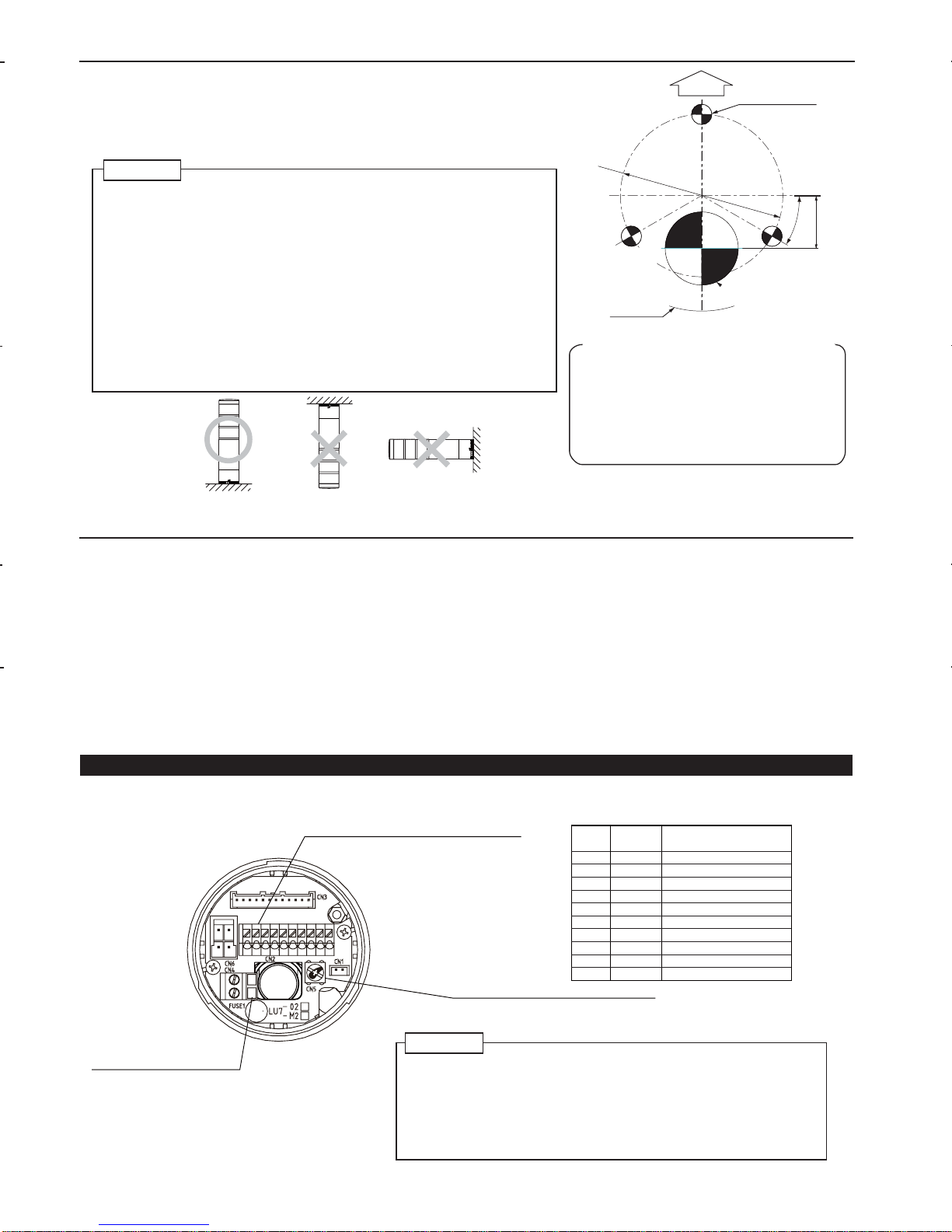
1. Confirm the hole position on the product.
2. Secure the template to the installation surface
using adhesive tape.
3. Mark the installation holes using nail punch,
etc.
4. Drill the holes in the installation surface.
※
Confirm the direction of the name plate and
the wiring route before you drill the holes.
Using this template
4. Installation
■
Mounting
●
Drill mounting holes in the wall. (See the following installation diagram.)
●
Secure the mounting bracket with the hex bolts and hex nuts.
●
Install the Signal Tower vertically at a location that has sufficient strength and minimal
vibration.
●
The alarm of buzzer models can be heard best from the front direction.
Therefore make sure the Signal Tower is facing the correct direction before install it.
● This product can be used only indoors. (Do not use it outdoors.)
● Do not install the Signal Tower horizontally or inverted.
(See the following "Mounting side" .)
● Make sure of the specified operating voltage and current before use.
● Do not use or keep without LED unit or Head cover installed.
● Use the soft cloth with moisture when the LED unit or Bse unit must be
cleaned up. (Do not use thinner, benzine, gasoline or oil.)
● During installation, do not remove the waterproof sheet. It may cause
a malfunction of water proof structure.
● This product has 1mm thick waterproof packing at the bottom of the pole
bracket. However, when complete waterproofing is not provided due to the
unevenness of the installation surface, apply waterproof sealant between the
unit and the installation surface to maintain waterproof conditions.
● When the cable gland is used, the hole must be the dimension that it can go
through. The cable which it can be used for is as follows;
Screw Size: M16×P1.5, Screw Length: Maximum 11mm,
Outer Diameter: Maximum 25mm, Material: Plastic.
Caution
5. Wiring Procedure
■
Wiring procedure
(Concerning the mark ※, the conditions about the product corresponding to UL are mentioned.)
●
Please make wiring connection according to wiring example.
●
For wiring of 5 layers or less, please make wiring connection by increasing or decreasing external contacts in each layer according
to wiring example.
●
When using multiple LED units of the same color, make the contact capacity equal to the number of same color LED units multiplied
by the contact capacity for 1 light. (This is because LED units of the same color light up for one signal line.)
※
Fuse for protection of external contact should be installed within 305mm from the connected point of the power source wire.
●
When wiring is completed, insulate the end of each unused lead wire by using insulation tape.
※
Use "Class Ⅱ Circuit" for the power supply source. Concerning fuse and fuse-holder, be sure to use the products authorized
by UL Inc.
※
Use the fuse conforming to the rated current of the machine. ( Example : Class J type fuse )
※
For the 90〜250V AC model, connect the green/yellow lead wire to the ground.
●
If you have any questions about simultaneous use of multiple units or other special operations,
contact PATLITE Customer Service before wiring.
Unit:mm
Mounting hole
3-φ5
Name plate
Buzzer
transmission
direction
Installation
template
5-1. Wiring example for Base unit [Terminal block]
CN4:For high voltage
(90-250V type)
Tighten torque 0.6N
・
m
CN2:For signal and low voltage (24V type)
CN5:For Earth ( Tighten torque : 1.2N
・
m )
1
2
3
4
5
6
7
8
9
10
Terminal
No.
Red
Orange
Green
Blue
White
Gray
Black
Yellow
Gray
Black
Front
Terminal
color
LED unit Red
LED unit Amber
LED unit Green
LED unit Blue
LED unit White
Buzzer1:Pi…(Continuous)
Buzzer2:Pi・Pi
…
Power supply(Continuous COM)
Flashing COM
Power supply
Corresponding unit
or operation
※
Recommendable wire type / dia
UL1007AWG22
~16
※
Recommendable wire type / dia:UL1015AWG18~14
※
Strip length of lead wires: 10mm
※
Recommendable wire type / dia:UL1015AWG18~14
※
Use the lead wire with the color of green or green/yellow for the earth wire.
UL1430AWG22
~16
※
Use 75℃ CU Wire only.
①
Upright
②
Invert
③
Horizontal
※
Strip length of lead wires: 9mm
VOL.
VOL.
VOL.
●
Remove Body from Base unit.(In case of 24V type, refer to "6. Unit reformation" .)
●
In case of 90-250V type, refer to "5-1-2. Wiring procedure for 90-250V type," Be sure to disengage the Screw before removing
the Body from Terminal block.
[Mounting side]
〔
Terminal block
〕
●
Never fail to observe the strip length of lead wire. Excessively short strip length causes
connection failure and excessively long strip length gives rise to electric shock or short
circuit, which are extremely dangerous.
●
While wiring this product, take care to avoid short-circuits from loose wire strands or
similar conditions.
●
Do not use unnecessarily strong force to separate the Terminal block and the Body.
Inside wiring may be damaged and may cause failure.
●
Connect high-voltage power supply cable to the specified terminals in the Terminal block.
Failure to connect this cable correctly will burn out the internal circuit.
Caution
Wire
Exit(φ18)
※When cable gland is used
(φ23)
φ40
13
3
0
°
Page 3
-8-
Red・Amber: 52mA Green・Blue・White:42mA
90~250V AC
24V DC
360mA
Is≧100mA, Vs≧35V AC
50mA
Is≧500mA
Vs≧35V AC
Is≧100mA
Vs≧250V AC
Is≧100mA, Vs≧35V AC
100mA
50mA
Voltage specs.
LED unit
〔1-Light〕
Current consumption
【External contact capacity】
Power supply
Contact capacity
※Is:Current capacity
Vs:Withstand voltage
Buzzer
Inrush current
Current consumption
● Make sure the power is OFF before wiring. A short circuit may damage internal circuits or cause an electric shock.
● Do not apply voltage directly to signal wires and common wires. It may damage the circuit. ( 90~250V AC )
● Do not pull out the lead wire or push it into the pole or the body.
● Install the external contact fuse on the power supply side as shown in the wiring example in order to prevent
burn in case of a wiring error.
● Failure to follow wiring instructions may cause damege to product or product may not operate properly.
● Do not apply voltage directly to Flashing common wire. It may cause a breakdown. ( FB type )
● Do not connect Continuous common wire and Flashing common wire. It may damage the internal circuit.
● If using both flashing and continuous circuits, do not apply power at the same time as this may cause second color
indicator to light. This also applies to both alarm circuits.
● If you use the product with both alarms, please use external contacts for lighting and for alarms.
Caution
Contact capacity
Current consumption
Contact capacity
■24V DC
■90~250V AC
1A
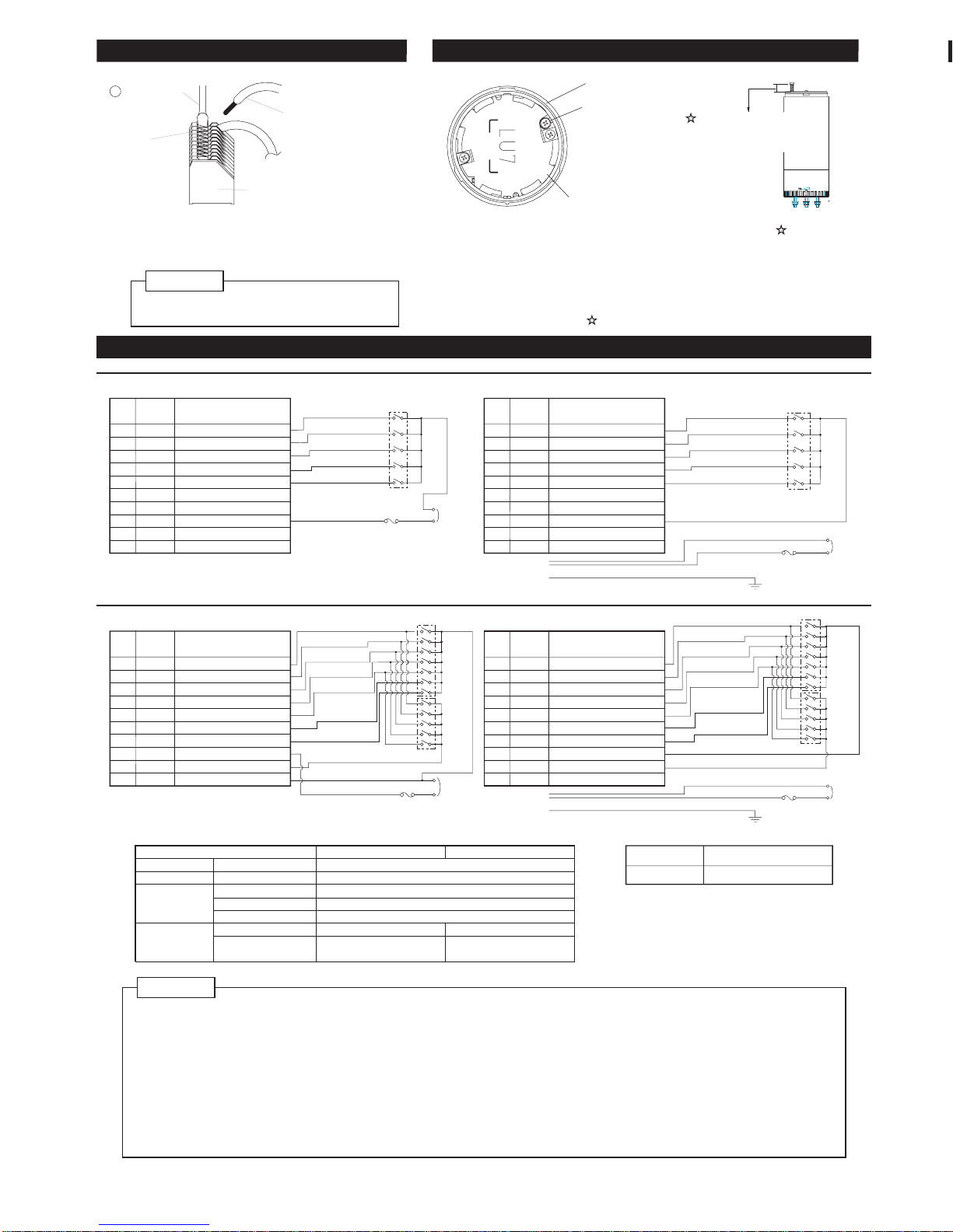
5-2. Wiring example
LU7 [ Continuous light type ]?
Power supply
Power
supply
LED White
LED Blue
LED Green
LED Amber
LED Red
External
contact fuse
Power supply
Continuous COM
Continuous light
Continuous COM
External
contact
Earth wire
■24V DC
■90~250V AC Type
1A
1A
【External contact fuse】
250V 1A
Voltage
Ampere rating of fuse
All model
LU7-FB [ Continuous light or Flashing, with Buzzer type ]
Flashing COM
Flashing
LED White
LED Blue
LED Green
LED Amber
LED Red
Buzzer 2
Buzzer 1
Continuous COM
Power supply
External
contact fuse
Continuous light
with Buzzer
Flashing COM
Continuous COM
supply
Power
External
contact
Flashing
Continuous light
with Buzzer
External
contact
External
contact
External
contact fuse
※Use the fuse conforming to the rated current of
the machine which you install product.
(Example : UL Class J type fuse)?
※Since a maximum of 10A inrush current flows
through the power supply wires, select contacts
with enough capacity to handle the inrush current.
LED White
LED Blue
LED Green
LED Amber
LED Red
Continuous light
External
contact
1A
supply
External
contact fuse
Power
Power supply
LED White
LED Blue
LED Green
LED Amber
LED Red
Buzzer 2
Buzzer 1
Power supply
Power supply
Earth wire
■LU7- FB [ Continuous light or Flashing, with Buzzer type ]
PNP Transistor ( 24V Type )
NPN Transistor ( 24V Type )
● When you use FB (Continuous light or Flashing, with Buzzer) type, you need the I/O unit respectively.
1
2
3
4
5
6
7
8
9
10
Terminal
No.
Red
Orange
Green
Blue
White
Gray
Black
Yellow
Gray
Black
Terminal
color
LED unit Red
LED unit Amber
LED unit Green
LED unit Blue
LED unit White
Buzzer1:Continuous
Buzzer2:Pi・Pi・・
Power supply(Continuous COM)
Flashing COM
Power supply
Corresponding unit
or operation
[CN2]
[CN2]
Connect to [CN4]:
Connect to [CN5]:
1
2
3
4
5
6
7
8
9
10
Terminal
No.
Red
Orange
Green
Blue
White
Gray
Black
Yellow
Gray
Black
Terminal
color
LED unit Red
LED unit Amber
LED unit Green
LED unit Blue
LED unit White
Buzzer1:Continuous
Buzzer2:Pi・Pi・・
Power supply(Continuous COM)
Flashing COM
Power supply
Corresponding unit
or operation
[CN2]
[CN2]
1
2
3
4
5
6
7
8
9
10
Terminal
No.
Red
Orange
Green
Blue
White
Gray
Black
Yellow
Gray
Black
Terminal
color
LED unit Red
LED unit Amber
LED unit Green
LED unit Blue
LED unit White
Buzzer1:Continuous
Buzzer2:Pi・Pi・・
Power supply(Continuous COM)
Flashing COM
Power supply
Corresponding unit
or operation
1
2
3
4
5
6
7
8
9
10
Terminal
No.
Red
Orange
Green
Blue
White
Gray
Black
Yellow
Gray
Black
Terminal
color
LED unit Red
LED unit Amber
LED unit Green
LED unit Blue
LED unit White
Buzzer1:Continuous
Buzzer2:Pi・Pi・・
Power supply(Continuous COM)
Flashing COM
Power supply
Corresponding unit
or operation
[CN2]
[CN2]
1
2
3
4
5
6
7
8
9
10
Terminal
No.
Orange
Green
Yellow
Terminal
1
2
3
4
5
6
7
8
9
10
Terminal
No.
Orange
Green
Yellow
Terminal
Connect to [CN4]:
Connect to [CN5]:
Base unit
Front
Insulation sheet
Screw for fitting Body
with Terminal block ( )
① Disengage Screw for fitting Body with Terminal block ( ).
※Make sure Screw for fitting Body with Terminal block springs up 5 mm or more.
② Remove Body from Terminal block.
(Refer to "6. Unit reformation" .)
③ Wire each lead wire.
(Refer to "5-1. Wiring example for Base unit" .)
④ Assemble Body with Terminal block.
⑤ Tighten the screw( ) and wiring is completed.
※The appearance when Head cover
is removed from Base unit.
5-1-1. Wiring procedure for a terminal[CN2]
5-1-1. ターミナル結線方法:[CN2]
5-1-2. Wiring procedure for 90-250V type
-Screw driver
Terminal
Lever
Lead wires
① Press the lever with screw driver etc.
② Insert the stripped portion of the lead wire all
the way into Terminal block.
③ Release the lever and wiring is completed.
(Non polar)
Power
supply
(Non polar)
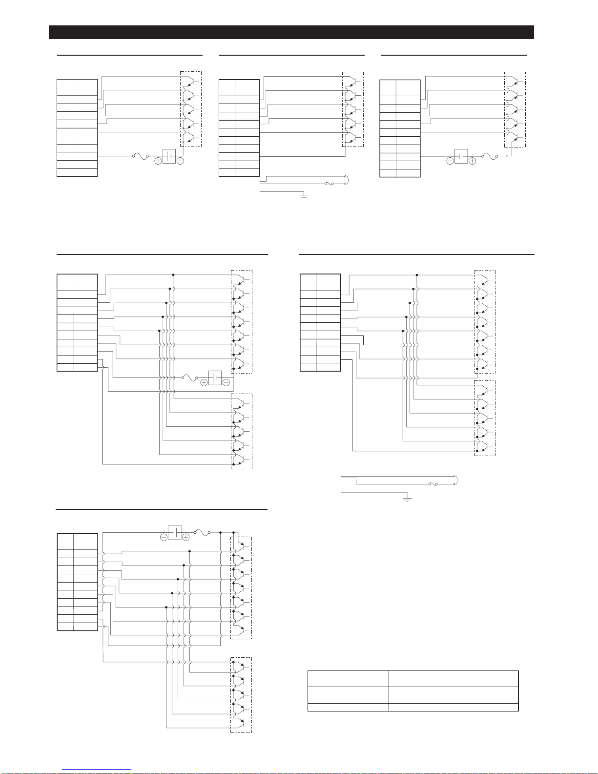
5-3. NPN ( PNP ) Transistor drive example
■LU7 [ Continuous light ]
NPN Transistor ( 24V Type )
[CN2]
1
2
3
4
5
6
7
8
9
10
Terminal
No.
Orange
Green
Yellow
Terminal
● When removing the lead wire, be sure to
operate the lever first, before pulling the wire out.
Caution
※Make sure Screw for
fitting Body with
Terminal block springs
up 5 mm or more.
Page 4
-9-
■LU7- FB [ Continuous light or Flashing, with Buzzer type ]
PNP Transistor ( 24V Type )
NPN Transistor ( 24V Type )
LED White
LED Blue
LED Green
LED Amber
LED Red
1A
Power supply wire
Current capacity
Vc≧35V
IL≦0.1mA
(LED unit)
(Buzzer)
Dielectric break
down strength
Leak current
Flashing
I/O Unit
Continuous
I/O Unit
Power
Supply
External
contact
Fuse
Buzzer 1
Buzzer 2
Continuous COM
Flashing COM
External
contact fuse
Continuous
I/O Unit
Flashing
I/O Unit
Flashing COM
Continuous COM
24V DC
24V DC
● When you use FB (Continuous light or Flashing, with Buzzer) type, you need the I/O unit respectively.
Recommendation transistor
NPN Transistor ( 90~250V Type )
Continuous
I/O Unit
1A
Power
Supply
External
contactf use
Power supply wire
Power supply wire
Flashing COM
Continuous COM
LED White
LED Blue
LED Green
LED Amber
LED Red
Buzzer 1
Buzzer 2
LED White
LED Blue
LED Green
LED Amber
LED Red
Buzzer 1
Buzzer 2
Power supply
Flashing
I/O Unit
Power
Supply
Earth wire
[CN2]
[CN2]
Connect to [CN4]:
Connect to [CN5]:
[CN2]
1
2
3
4
5
6
7
8
9
10
Terminal
No.
Red
Orange
Green
Blue
White
Gray
Black
Yellow
Gray
Black
Terminal
color
1
2
3
4
5
6
7
8
9
10
Terminal
No.
Red
Orange
Green
Blue
White
Gray
Black
Yellow
Gray
Black
Terminal
color
1
2
3
4
5
6
7
8
9
10
Terminal
No.
Red
Orange
Green
Blue
White
Gray
Black
Yellow
Gray
Black
Terminal
color
1A
5-3. NPN ( PNP ) Transistor drive example
Earth wire
Power supply wire
Power supply wire
Continuous
COM
1A
1A
24V DC
Continuous
I/O Unit
Power
Supply
External
contact
fuse
LED White
LED Blue
LED Green
LED Amber
LED Red
Power
Supply
External
contact fuse
24V DC
■LU7 [ Continuous light ]
PNP Transistor ( 24V Type )
NPN Transistor ( 24V Type )
NPN Transistor ( 90~250V Type )
Continuous COM
LED White
LED Blue
LED Green
LED Amber
LED Red
1A
Power
Supply
External
contact fuse
Continuous
I/O Unit
Continuous
COM
LED White
LED Blue
LED Green
LED Amber
LED Red
[CN2]
[CN2]
[CN2]
1
2
3
4
5
6
7
8
9
10
Terminal
No.
Red
Orange
Green
Blue
White
Gray
Black
Yellow
Gray
Black
Terminal
color
1
2
3
4
5
6
7
8
9
10
Terminal
No.
Red
Orange
Green
Blue
White
Gray
Black
Yellow
Gray
Black
Terminal
color
1
2
3
4
5
6
7
8
9
10
Terminal
No.
Red
Orange
Green
Blue
White
Gray
Black
Yellow
Gray
Black
Terminal
color
Continuous
I/O Unit
Connect to [CN4]:
Connect to [CN5]:
Ic≧100mA
Page 5
-10-
4. Installation
■
Mounting
●
Drill mounting holes in the wall. (See the following installation diagram.)
●
Secure the mounting bracket with the hex bolts and hex nuts.
●
Install the Signal Tower vertically at a location that has sufficient strength and minimal
vibration.
●
The alarm of buzzer models can be heard best from the front direction.
Therefore make sure the Signal Tower is facing the correct direction before install it.
● This product can be used only indoors. (Do not use it outdoors.)
● Do not install the Signal Tower horizontally or inverted.
(See the following "Mounting side" .)
● Make sure of the specified operating voltage and current before use.
● Do not use or keep without LED unit or Head cover installed.
● Use the soft cloth with moisture when the LED unit or Bse unit must be
cleaned up. (Do not use thinner, benzine, gasoline or oil.)
● During installation, do not remove the waterproof sheet. It may cause
a malfunction of water proof structure.
● This product has 1mm thick waterproof packing at the bottom of the pole
bracket. However, when complete waterproofing is not provided due to the
unevenness of the installation surface, apply waterproof sealant between the
unit and the installation surface to maintain waterproof conditions.
● When the cable gland is used, the hole must be the dimension that it can go
through. The cable which it can be used for is as follows;
Screw Size: M16×P1.5, Screw Length: Maximum 11mm,
Outer Diameter: Maximum 25mm, Material: Plastic.
Caution
5. Wiring Procedure
■
Wiring procedure
●
Please make wiring connection according to wiring example.
●
For wiring of 5 layers or less, please make wiring connection by increasing or decreasing external contacts in each layer according
to wiring example.
●
When using multiple LED units of the same color, make the contact capacity equal to the number of same color LED units multiplied
by the contact capacity for 1 light. (This is because LED units of the same color light up for one signal line.)
※
Fuse for protection of external contact should be installed within 305mm from the connected point of the power source wire.
●
When wiring is completed, insulate the end of each unused lead wire by using insulation tape.
※
Use "Class
by UL Inc.
※
Use the fuse conforming to the rated current of the machine. ( Example : Class J type fuse )
※
For the 90
●
If you have any questions about simultaneous use of multiple units or other special operations,
contact PATLITE Customer Service before wiring.
5-1. Wiring example for Base unit [Terminal block]
CN4:For high voltage
Tighten torque 0.6N
※
Recommendable wire type / dia
※
Strip length of lead wires: 10mm
MIN
MAX
VOL.
■
Front
■
Bottom
● Please use a fuse specified by IEC 127.
● When lead wires are exposed outside the body during pole installation, etc. always provide double insulation using insulation tape
and vinyl tubing, etc.
● For the 90-250V type, use shielded cable for the power supply cable and be sure to connect the shield to ground (CN5).
● Do not turn the volume control forcibly.
It might damage the volume control.
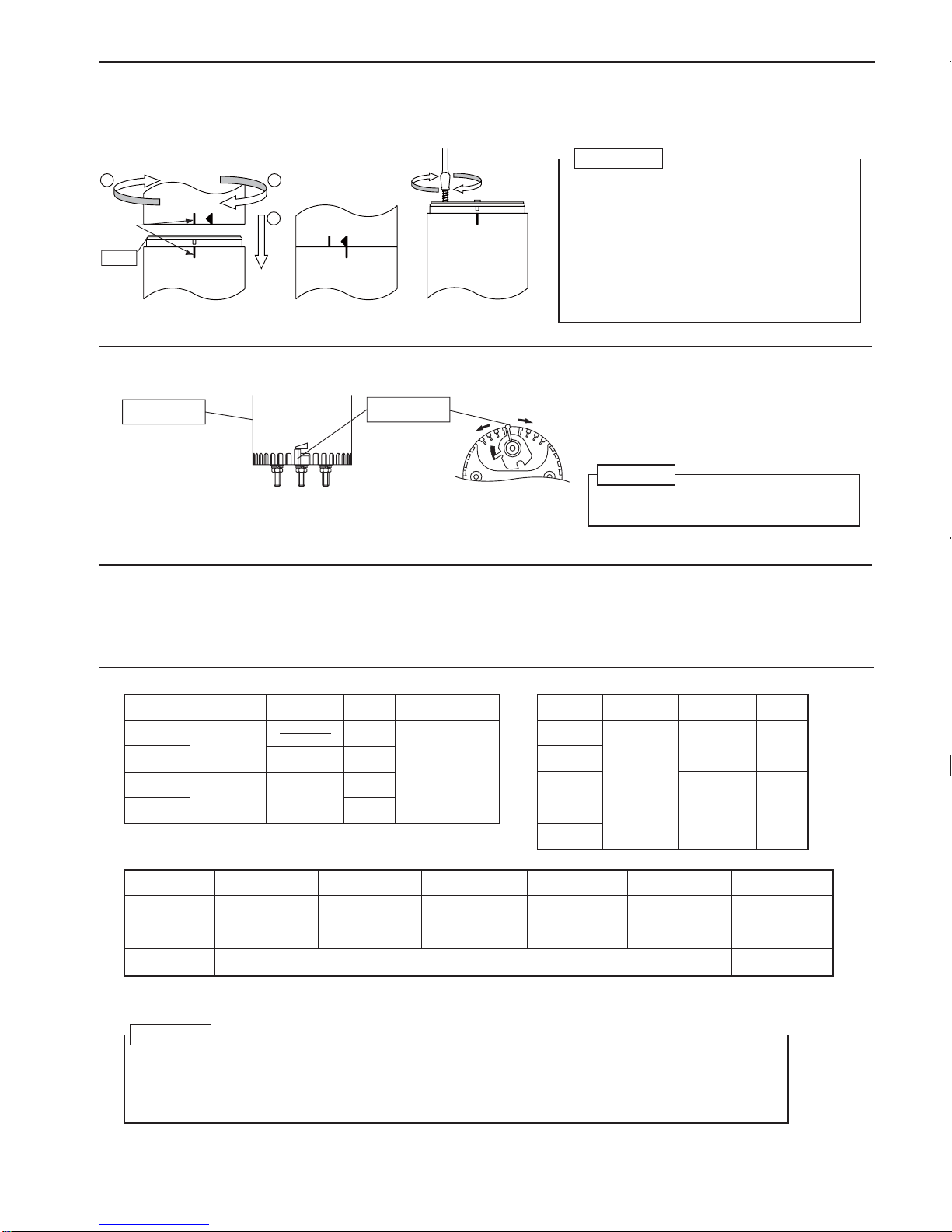
7. Volume adjustment
8. To use this product in accordance with the CE marking, please observe the followings
●
You can adjust the volume by turning the volume control at the bottom to the left or right.
Body
Volume
Caution
9. Specifications
● In the event that the tower is subject to continuous,excessiv shaking,vibration may be too strong and there is a danger
of breakage. Immediately stop using the tower and consult PATLITE Customer Service.
● PATLITE Corporation disclaims all liability for any malfunction or damage occurring as a result of handling contrary to
the instructions, cautions and warnings mentioned in this manual.
● Specifications may change without notice due to continual product improvement.
Caution
LU7-02
LU7-02FB
LU7-M2
LU7-M2FB
24V DC
Mass
Model
Rated voltage
Power
consumption
[
Base unit
]
90~250V AC
(50/60Hz)
LU7-E-R
LU7-E-A
LU7-E-G
LU7-E-B
LU7-E-C
24V DC
Mass
Model
Rated voltage
Power
consumption
[
LED unit
]
Flashing cycle and
Peak sound level
FB Type
60 Flashes
per minute
Sound level
70~90dB/m
※FB type only
1.2W
Buzzer:2.2W
Standby power
consumption:1.0W
250g
275g
350g
375g
1.3W
1.0W
60g
60g
●
Remove Body from Base unit.(In case of 24V type, refer to "6. Unit reformation" .)
●
In case of 90-250V type, refer to "5-1-2. Wiring procedure for 90-250V type," Be sure to disengage the Screw before removing
the Body from Terminal block.
●
Turn the power OFF before performing unit reformation.
●
First make sure the O-ring is mounted as shown in Drawing 1,then align the locating mark of each unit,and place the units together in
the direction of the arrow (①) as shown.
●
Rotate the upper unit in the direction of the arrow(②).(Refer to Drawing.2)
●
For 90-250V type Base Unit, tighten the Screw that secures the Body to the Terminal block.
6. Unit reformation
Caution
●
Do not remove a LED unit forcibly.
It may damage the unit.
●
Do not warp or damage the LED unit to a lower unit.
●
Make sure the O-ring is first mounted in position on
the Terminal block as shown in Drawing 1,
then place the Body on the O-ring.
●
If the Body is mounted to the Terminal block, do not
attempt to rotate either part with the Screw pushed in or
engaged.
●
Never attempt to tighten the Screw until the locating
mark is aligned with the arrow as shown in Drawing 2.
[Mounting side]
〔
Drawing.1
Drawing.2
1
2 2
a
Drawing.3
O ring
[Vibretion resistance]
1-Lights
4.5G 44.1m/s
2
4.5G 44.1m/s
2
2-Lights
3.5G 34.2m/s
2
4.5G 44.1m/s
2
3-Lights
2.0G 19.6m/s
2
1.9G 18.6m/s
2
10-150Hz
4-Lights
1.3G 12.7m/s
2
1.9G 18.6m/s
2
5-Lights
0.7G 6.8m/s
2
1.0G 9.8m/s
2
5-Lights
1.9G 18.6m/s
2
1.9G 18.6m/s
2
40-150Hz
Number of
LED units
LU7-02
LU7-M2
Allowable vibration
frequency
 Loading...