

Page 1
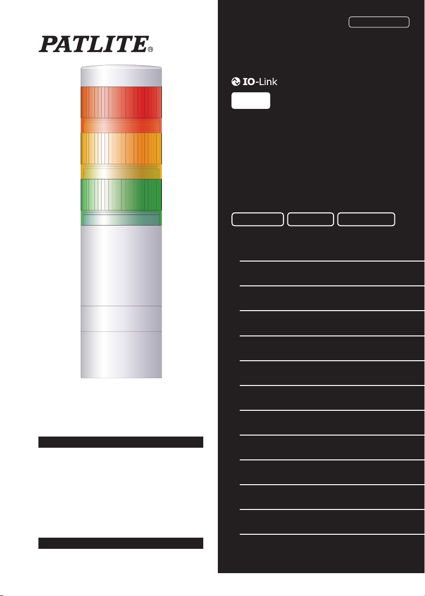
Signal Tower
GA0001002_02
TYPE
LR6-IL
Complete Operation
Manual
Installation Operation Maintenance
Page
1 Read this First
2 Model Number Confi guration
3 Names and Dimensions
4 Installation
5 Wiring
2
2
3
4
6
Notice to Customer
Thank you very much for purchasing our PATLITE
products.
Request the installation and wiring be performed by
a professional contractor if construction work is
involved.
Prior to installation, read this manual thoroughly
before using this product to ensure correct use.
If there are any questions concerning this product,
refer to the contact information at the end of this
document and contact your nearest PATLITE Sales
Representative.
To the Contractor
Read this manual carefully prior to installation.
Be sure to return this manual to the customer.
– 1 –
6 How to Use
7 Buzzer Settings
8 Detaching the Unit
9 Troubleshooting
10 Specifi cations
11 Service Parts
12 Optional Parts
7
9
10
22
23
25
26
Page 2
Read this First
1
Safety Precautions
The safety precautions that should always be followed in order to prevent injury to user or other individuals as well as
prevent damage to property are described below.
The level of injury or damage caused by ignoring these safety precautions and using the product improperly is categorized
and described below.
Warning
This icon indicates an action with the potential to
cause death or serious injury.
Caution
Warning
Request the installation and wiring be accompanied by
may result in
fi re, electric shock, falling
malfunction
, or
a professional contractor
.
Caution
Adhere to the items below to prevent
- Be sure that the product is
- Use this product in
Avoid long exposure to the Buzzer sound from a close distance.
permanent damage to the ears. (When Buzzer Unit is used)
In order to maintain protection of this product against dust and waterproofi ng performance,
cover, LED unit and buzzer unit in the condition that it was originally attached
To ensure the waterproofi ng performance of this product,
and waterproofi ng performance will decrease.
When removing covers or packing from the equipment, which is attached to this product, be careful
product. Failure to comply may result in damage to the product.
To ensure proper safety while using the signal tower, observe the following:
- Perform
- As a precaution against problems occurring,
Be sure to prevent electrostatic damage
units, setting up parameters, etc. by discharging static electricity on your body, etc.
(To prevent damage from static electricity, touch hands or other body parts to metals or an earth ground to discharge
the body from static charge.)
Use a soft cloth, etc., dampened with water to wipe the main unit. If wiped with chemicals outside water (thinner,
benzine, gasoline, oil, etc.), product damage may occur.
To ensure safety when this product is installed onto equipment, observe the following:
-
-
- Use only the specifi ed replacement parts listed in this document.
periodic pre-maintenance
Do not remove parts
Do not modify or disassemble
the proper state
beyond those designed to be removed from this product.
a short or damage
disconnected from the power source
. (Replace parts such as the body or each unit if damaged.)
.
do not remove the O-ring or the waterproof packing
when changing, replacing or adding a unit.
Failure to observe this may lead from irritation to
Notice
.
use this product together with other equipment
due to discharge when working with this product for wiring, exchanging
this product.
This icon indicates an action with the potential to
cause injury, physical loss or damage.
. If installation is done improperly, it
be sure to use the head
.
not to snag
.
. Dust
the
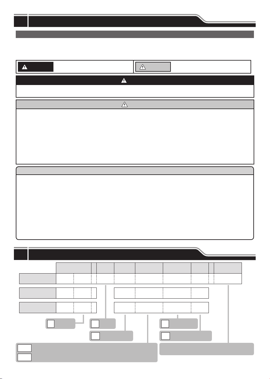
Model Number Confi guration
2
Tiers
IO-Link
Extended
Functionality
Model Tiers
Assembly Model
Unit Model
(Body Unit)
Unit Model
(Body Unit)
LR 6 - 3 IL WM N W - RYG
LR 6 - IL WM N W
LR 6 - IL WC N W
Φ60
6
3
IL
Direct Mount / M12 Connector (Mounting with 3 Hexagon Bolts)
WM
Direct Mount / M12 Connector (Mounting with M30 Nut)
WC
– 2 –
Mounting/
Wiring
Buzzer
No Flashing
N
Off-white
W
LED Color: R (Red) / Y (Amber) / G (Green)
(From top to bottom)
Body
Color
LED Unit
Color
Page 3
Names and Dimensions
3
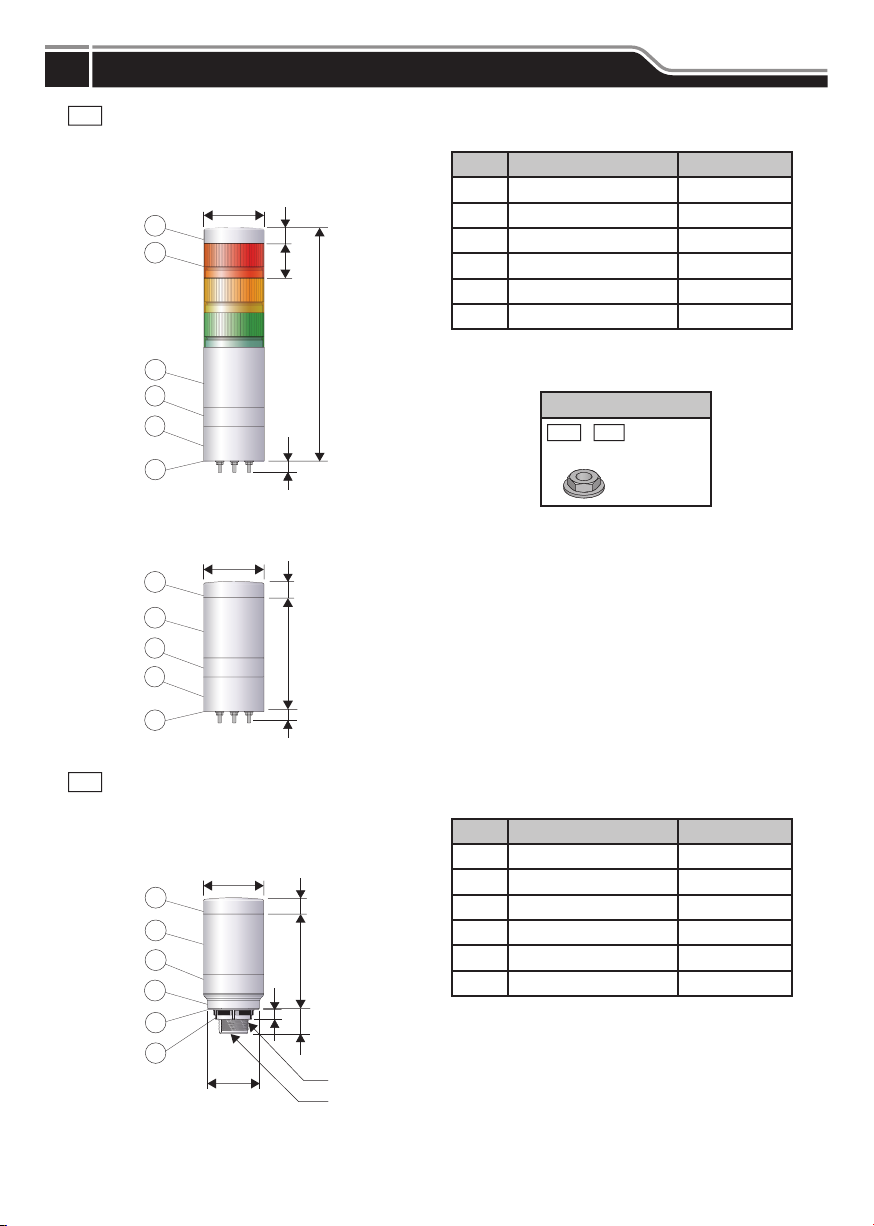
WM
Direct Mount/M12 Connector Specifi cations (3-point Screw Attachment)
(Unit: mm)
1
2
3
4
5
6
1
3
4
5
6
LR6-3ILWMNW
ĭ
LR6-ILWMNW
ĭ
19
40
19
132
No. Part Name Material
1 Head Cover PC
2 LED Unit Globe: PC
3 Body PC
4 M12 Bracket PC
5 Direct Mount Bracket PC
6 Waterproof Packing Silicone Rubber
271
* M12 connector cable is sold separately.
(Please use an M12 connector of Φ16 or less.)
Accessory
-
WM
LR6
12
Flanged nut (M4)
3 pcs.
12
Direct Mount/M12 Connector Specifi cations (M30 Nut Attachment)
WC
(Unit: mm)
1
2
3
4
5
6
LR6-ILWCNW
ĭ
ĭ
19
25
M30 × 1.5
1/2” NPT Internal
Threads
No. Part Name Material
1 Head Cover PC
2 Body PC
3 M12 Bracket PC
4 Direct Mount Bracket PC
5 Waterproof Packing Silicone Rubber
6 M30 Nut PC
* M12 connector cable is sold separately.
(Please use an M12 connector of Φ16 or less.)
– 3 –
Page 4
Installation
4
Notice
The following requirements are necessary for a proper mounting location.
- Location with
Install with the mounting direction in the
When the installation location is unavoidably irregular and waterproof performance is required, use a sealant between
the product and the installation surface.
strong
even surface
and
minimal vibration
with
upright position
.
.
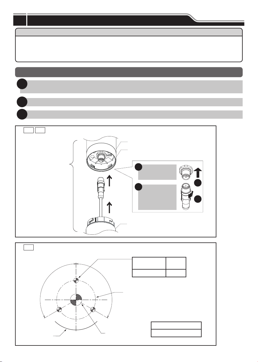
Basic Mounting Instructions
Make holes for the mounting and wire-distribution for the product.
1
(Check the Model and refer to the suitable mounting dimension fi gure.)
Connect to the product through the distribution hole.
2
Secure the product with the nuts.
3
WC Installation Figure (M12 Connector Installation Figure)
WM
Body
M12 Bracket
Connect to the M12
Connector through the
distribution hole.
Mounting Dimensional Drawing
WM
(Unit: mm)
120°
Nameplate
Position
Direct Mount Bracket
Mounting Hole
120°
ĭ40
Wire Distribution Hole
(Φ20)
Connect cabel
1
to the M12
Connector.
Turn the
2
connected
cable in the
direction of the
arrow.
(3 places)
Φ5M4
Screw/
Nut
Recommended Torque
0.6 N·m
1
2
– 4 –
Page 5
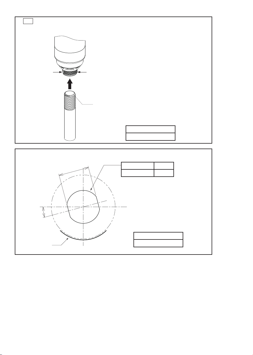
WC
Installation Figure (1/2” NPT Installation Figure)
While holding part ‘A’, install the 1/2” NPT.
Failure to comply may result in damage.
AA
1/2” NPT
Mounting Dimensional Drawing
(Unit: mm)
28.5
Recommended Torque
2.25 N·m
Mounting Hole Nut
Φ31 M30
15°
Nameplate
Position
Recommended Torque
4.5 N·m
– 5 –
Page 6
Wiring
5
Warning
the proper working voltage
Ensure
Any mistake in wiring may result in damage or fi re.
is used and that
direct current or alternating current
Caution
Do not pull
the wire, or
stuff it inside
of this product. Possible cause of failure may occur.
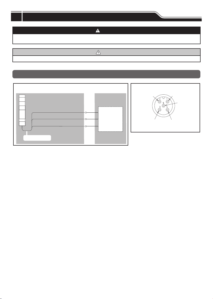
Wiring Example and M12 Connector Pin Layout
is properly applied.
Wiring Example
L+ (Pin-1)
IO-Link C/Q (Pin-4)
L- (Pin-3)
M12 Connecter
IO-Link Master
L+
C/Q
L-
M12 Connector Pin Layout
N.C.
L-
Connector type: M12, 5-pins, A code
L+
N.C.
IO-Link C/Q
– 6 –
Page 7
How to Use
6
This product is an IO-Link compliant product.
Connect this product by following the “
The controller can light, fl ash or extinguish the LEDs or control the buzzer.
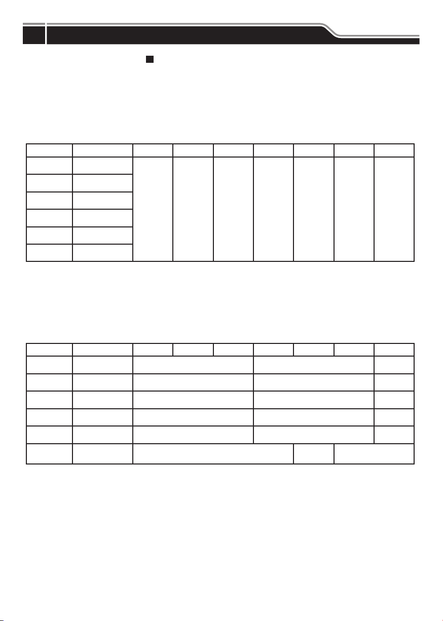
Changing the “Operating Mode” settings enables the following modes:
Simple Mode
Advanced Mode
Simple Mode
This mode performs simple control by only turning ON and OFF each LED and the buzzer.
Other settings are specifi ed using the parameters.
Send the processed data by referring to the table below.
5 Wiring” (p. 6).
bit 0 bit 1 bit 2 bit 3 bit 4 bit 5 bit 6 bit 7
Byte 0 data
Byte 1 data
Byte 2 data
Byte 3 data
Byte 4 data
Byte 5 data
Advanced Mode
This mode performs advanced control such as lighting, fl ashing, and turning off each LED as well as sounding,
intermittently beeping, or stopping the buzzer.
Other settings are specifi ed using the parameters.
Send the processed data by referring to the table below.
Enable the intermittent buzzer settings to repeatedly sound the buzzer for 500 ms and stop the buzzer for 500 ms.
Refer to (p. 8) for the pattern of each LED.
LED Unit (Red)
ON / OFF
LED Unit (Amber)
ON / OFF
LED Unit (Green)
ON / OFF
LED Unit (Blue)
ON / OFF
LED Unit (White)
ON / OFF
Buzzer
ON / OFF
Not used Not used Not used Not used Not used Not used Not used
Byte 0 data
Byte 1 data
Byte 2 data
Byte 3 data
Byte 4 data
Byte 5 data
bit 0 bit 1 bit 2 bit 3 bit 4 bit 5 bit 6 bit 7
LED Unit (Red)
ON / OFF
LED Unit (Amber)
ON / OFF
LED Unit (Green)
ON / OFF
LED Unit (Blue)
ON / OFF
LED Unit (White)
ON / OFF
Buzzer
ON / OFF
Not used LED pattern (Red) Not used
Not used LED pattern (Amber) Not used
Not used LED pattern (Green) Not used
Not used LED pattern (Blue) Not used
Not used LED pattern (White) Not used
Not used
Intermittent
Buzzer
– 7 –
Not used
Page 8
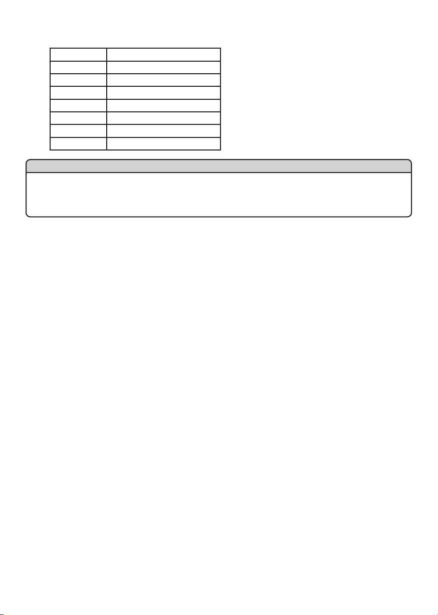
LED Pattern
Setting Description
0 Lit Example: Byte 0 data = 01h Red Light
1 1 sec. Flash (Slow)
2 500 ms Flash (Medium)
3 250 ms Flash (Fast)
4 Single Flash
5 Double Flash
6 Triple Flash
Byte 1 data = 11h Amber Flashing
Byte 2 data = 31h Green Flashing
Byte 3 data = 61h Blue Triple
Byte 4 data = 00h White OFF
Byte 5 data = 11h Intermittent
(1 sec Cycle)
(250 ms Cycle)
Flash
Buzzer
Notice
Settings 4, 5 and 6 cannot be used with the Multicolor LR6-E-MZ of the LED Unit.
Each LED may not light correctly.
Settings 4, 5 and 6 cannot be used with the WD transmitter for the wireless data communication system.
The correct data may not be acquired.
The intermittent buzzer and the LED pattern do not synchronize.
Parameter Settings
For information about the parameter settings, please download the IODD from the LR6-IL page on our homepage (https://
www.patlite.com/).
Please also download and use the parameter sheet in the same way.
– 8 –
Page 9
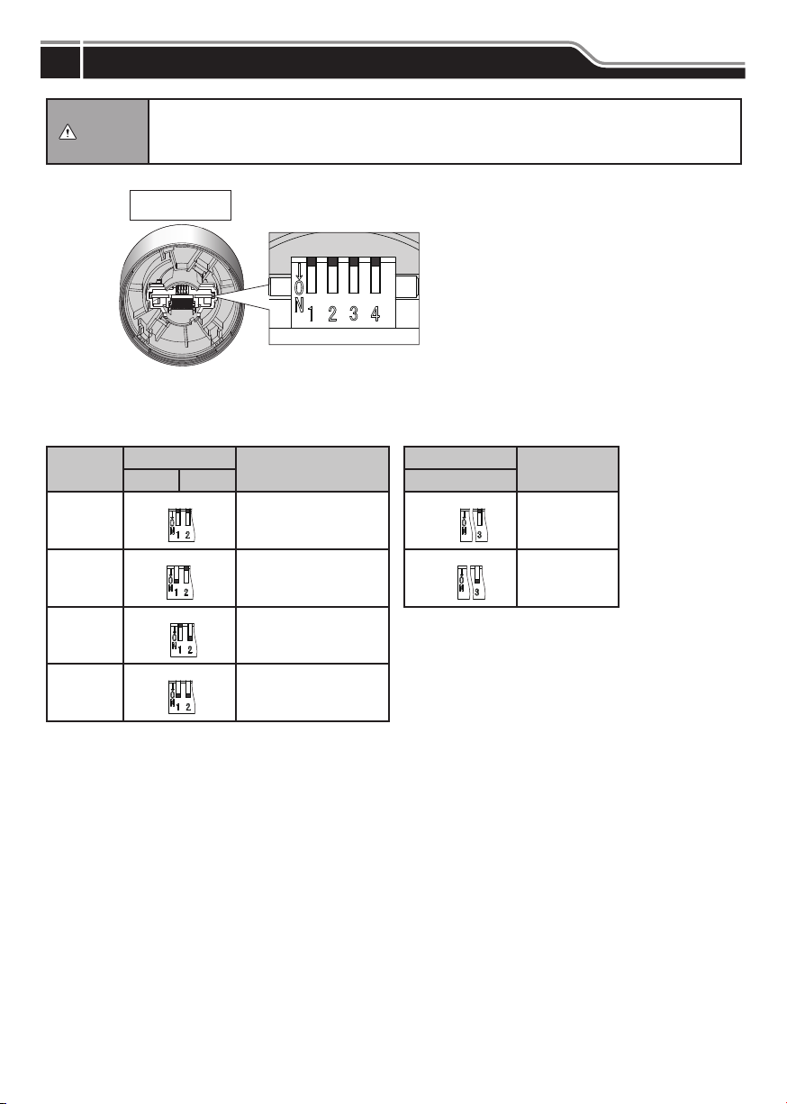
Buzzer Settings
7
Do not use excess force when performing operations.
Caution
DIP Switch Confi guration Table
to breakage or deformation.
Do not use sharp-pointed objects to perform operations.
and inoperative switches or hinder contact between contact parts.
Buzzer Unit
Bottom View
■ Indicates the position of the DIP
switch. (Down to turn “ON”.)
Failure to comply will result in damage due
Failure to comply may result in damage
Buzzer
Sound
No. 1
No. 2
No. 3
No. 4
DIP Switch
12 3
OFF OFF
ON OFF
OFF ON
ON ON
Sound Pattern
Rapid intermittent beep
(call sign)
Continuous beep sound
Rapid hi-low
Sweep sound
DIP Switch
OFF
ON
Note: DIP Switch 4 is not used.
The factory default settings have all of the DIP
switches in the “OFF” (Up) position.
Volume
Normal
Noise reduction
– 9 –
Page 10

Detaching the Unit
8
Follow the procedure below to detach a unit, such as when removing the Buzzer Unit or changing the layout of the LED
Units.
Link to Video
Caution
Be sure that it is disconnected from the power source before working on it.
Do not apply excessive torque
malfunction.
Do not touch the connector area or the inside of the body and LED unit.
malfunction.
Be sure to lock
Detach the unit in the following manner. Any other method may result in damaging the product.
Attachment: Attach one unit at a time to the body.
Removal: Firmly hold the bottom section while removing the upper section.
Please attach each unit
from the Body Unit one at
a time.
each unit securely when attaching. Failure to comply will result in damage or malfunction.
strong shock
or
to each unit or body. Failure to comply will result in damage or
Failure to comply will result in damage or
Units may become
damaged if attached from
the top side.
Notice
The maximum number of attachment units per product are fi ve LED units, plus one buzzer unit.
When using the Multi-Color LED Unit LR6-E-MZ for the LR6 (60 mm) Signal Tower, the maximum number of attachment
units per product is one LED unit and one buzzer unit.
When using Wireless Data Acquisition System WD, the maximum number of attachment units per product are three
LED units.
– 10 –
Page 11

<LED/Buzzer Unit>
Removal
Attachment
LED Unit or Buzzer Unit
Body or LED Unit
Turn the body or LED unit counter-clockwise to unlock,
then raise upwards to remove it.
Positioning Mark
<Locked> <Unlocked>
Align the Positioning Mark after insertion, then turn the
unit clockwise to lock it.
Align the positioning marks
after attachment.
– 11 –
Positioning Mark
<Unlocked> <Locked>
Page 12
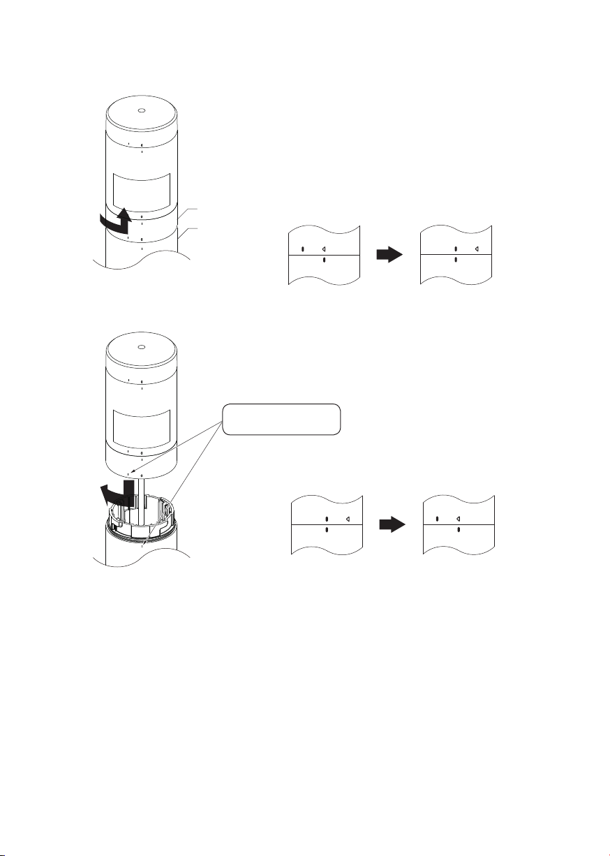
<Body Unit>
Removal
Attachment
M12 Bracket
Direct Mount
Bracket
Align the positioning marks
after attachment.
While holding the Direct Mount Bracket, turn the M12
Bracket counter-clockwise, until it unlocks, then pull it
upwards to remove.
Positioning Mark
<Locked> <Unlocked>
Align the Positioning Mark after insertion, then turn the
unit clockwise to lock it.
Positioning Mark
<Unlocked> <Locked>
– 12 –
Page 13
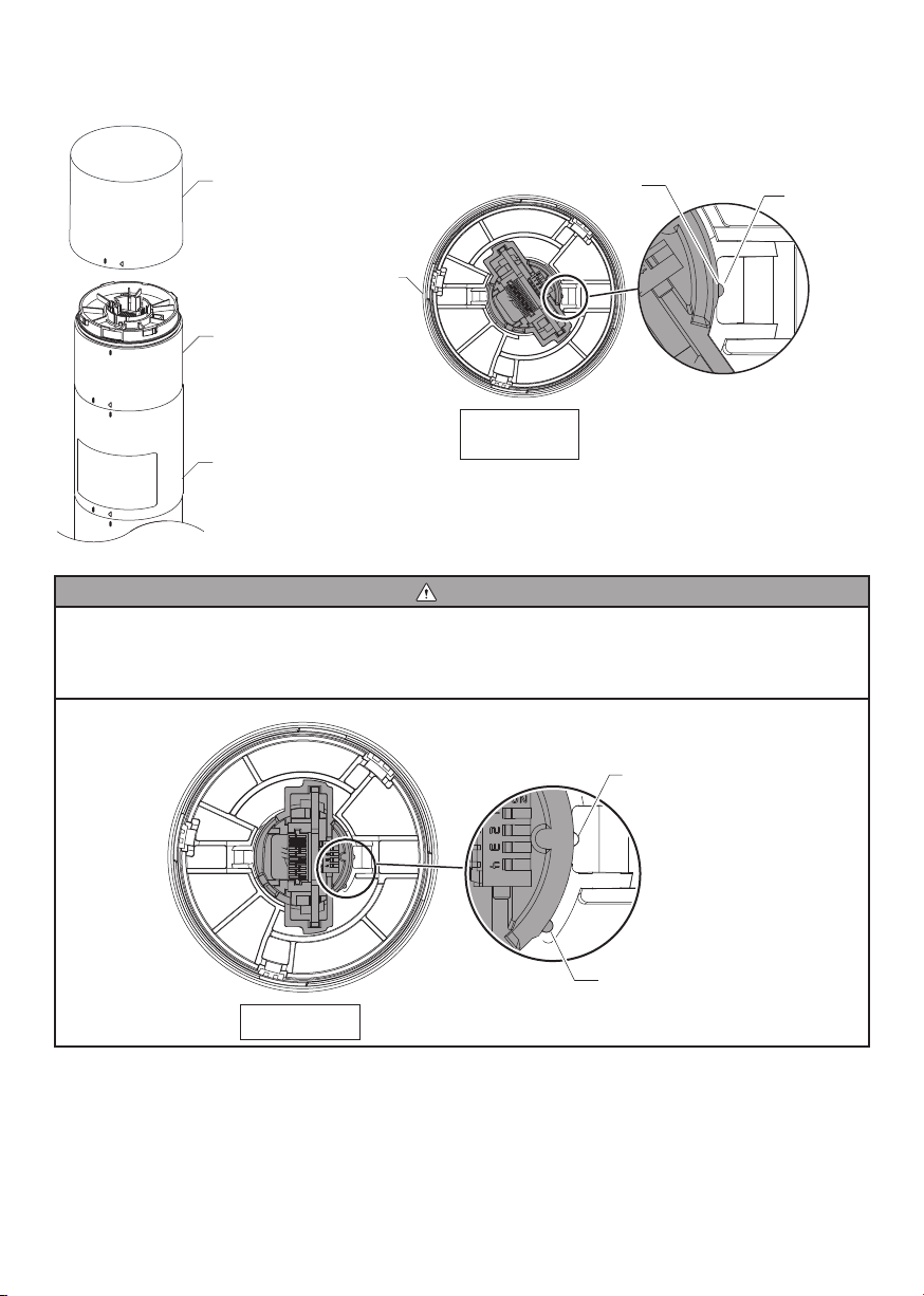
<Troubleshooting the Buzzer Unit Attachment>
The Buzzer Unit is generally in the status shown in the diagram below after removal.
Buzzer Unit
LED Unit
Body
Positioning
Mark
Buzzer Unit
(Detached)
Bottom View
The rib inside of the Buzzer Unit fi ts into the groove when the
Buzzer Unit has been removed from the product.
Rib
Groove
Caution
Check to make sure the rib inside of the Buzzer Unit fi ts into the groove if the Buzzer Unit does not attach properly. Attach
the Buzzer Unit by referring to the next page if the rib does not fi t into the groove as shown in the diagram below.
In addition, the rib may slide out of the groove during removal as shown in the diagram below depending on how the
Buzzer Unit was removed.
Attaching the Buzzer Unit to the product again in this state may result in damage.
Groove
Buzzer Unit
Bottom View
Rib
– 13 –
Page 14

Use the procedure below if the Buzzer Unit does not attach properly.
Turn the part inside the Buzzer Unit in the counter-clockwise direction.
Turn until the rib fi ts into the groove, then attach the Buzzer Unit to the
product.
Turn this part in the
counter-clockwise direction.
Buzzer Unit
Bottom View
Rib
Groove
– 14 –
Page 15
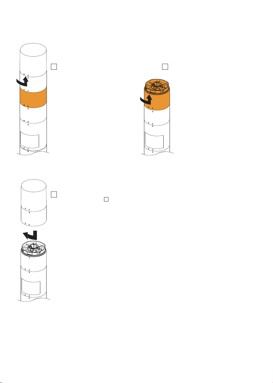
<Example for LED Unit Reconfi guration>
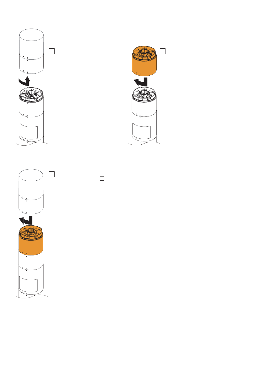
Moving an LED Unit lower
1 Remove the LED Unit right above the LED
Unit in the area to remove.
3 Align the positioning marks and insert the LED
Unit that was removed in
LED Unit clockwise to lock it in place.
1
, then turn the
2 Turn the LED Unit to remove counter-
clockwise while holding the adjacent LED unit
to release the lock, then pull upward.
– 15 –
Page 16
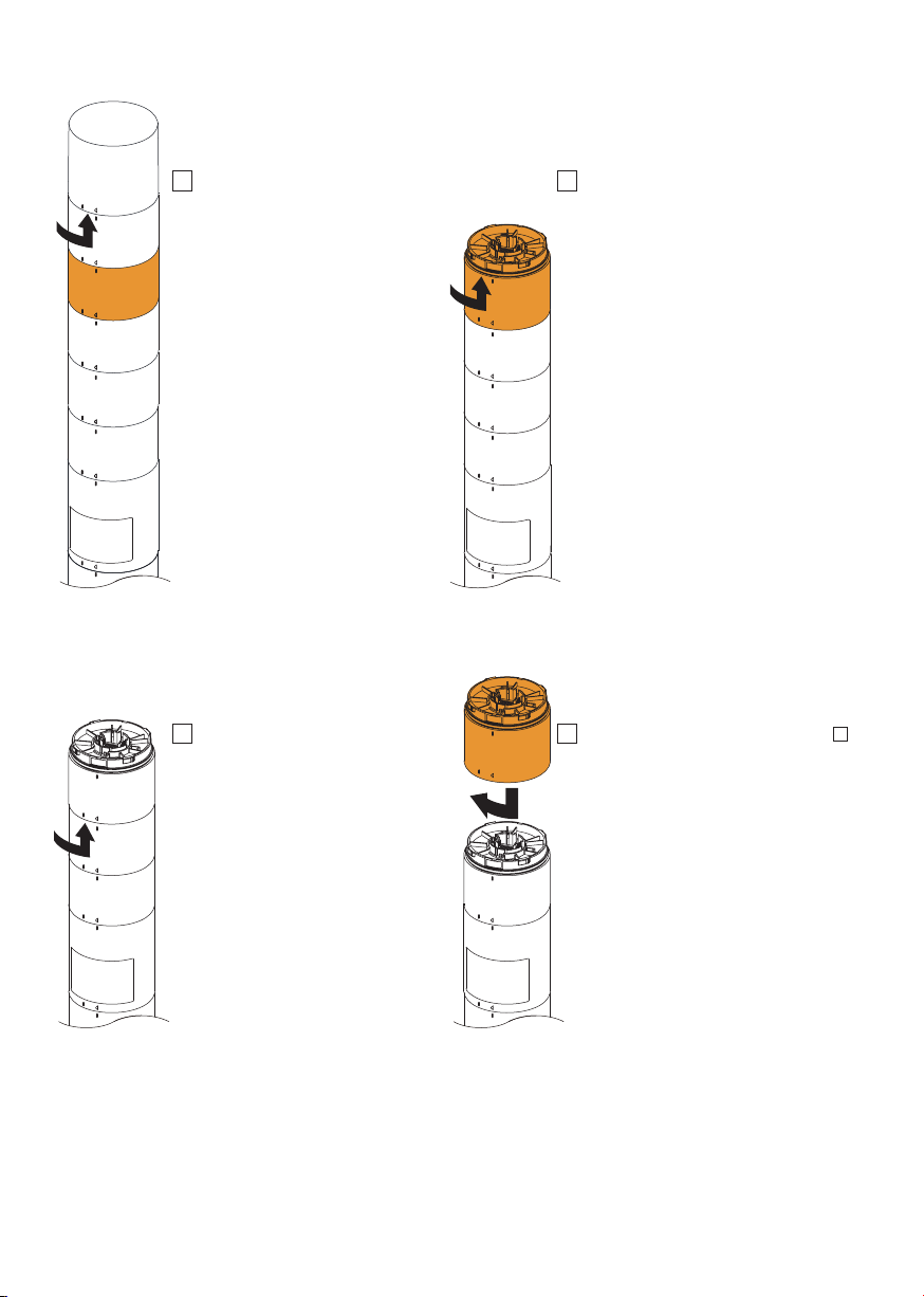
Adding an LED Unit
1 Remove the LED Unit above the area to
attach an additional LED unit.
3 Align the positioning marks and insert the LED
Unit that was removed in
LED Unit clockwise to lock it in place.
1
, then turn the
2 Align the positioning marks and insert the
LED Unit, then turn the LED Unit
clockwise to lock it in place.
– 16 –
Page 17
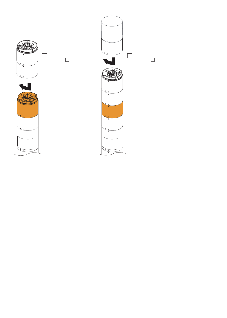
Changing the Position of an LED Unit
1 Remove the LED Unit right above the
LED Unit that will be changing postitions.
3 Remove the LED Unit right above the
position to add the LED unit.
2 Remove the LED Unit that will be changing
positions.
4 Attach the LED Unit that was removed in 2.
– 17 –
Page 18
5 Attach the LED Unit that was
removed in
3
.
6 Attach the LED Unit that was
removed in
1
.
– 18 –
Page 19
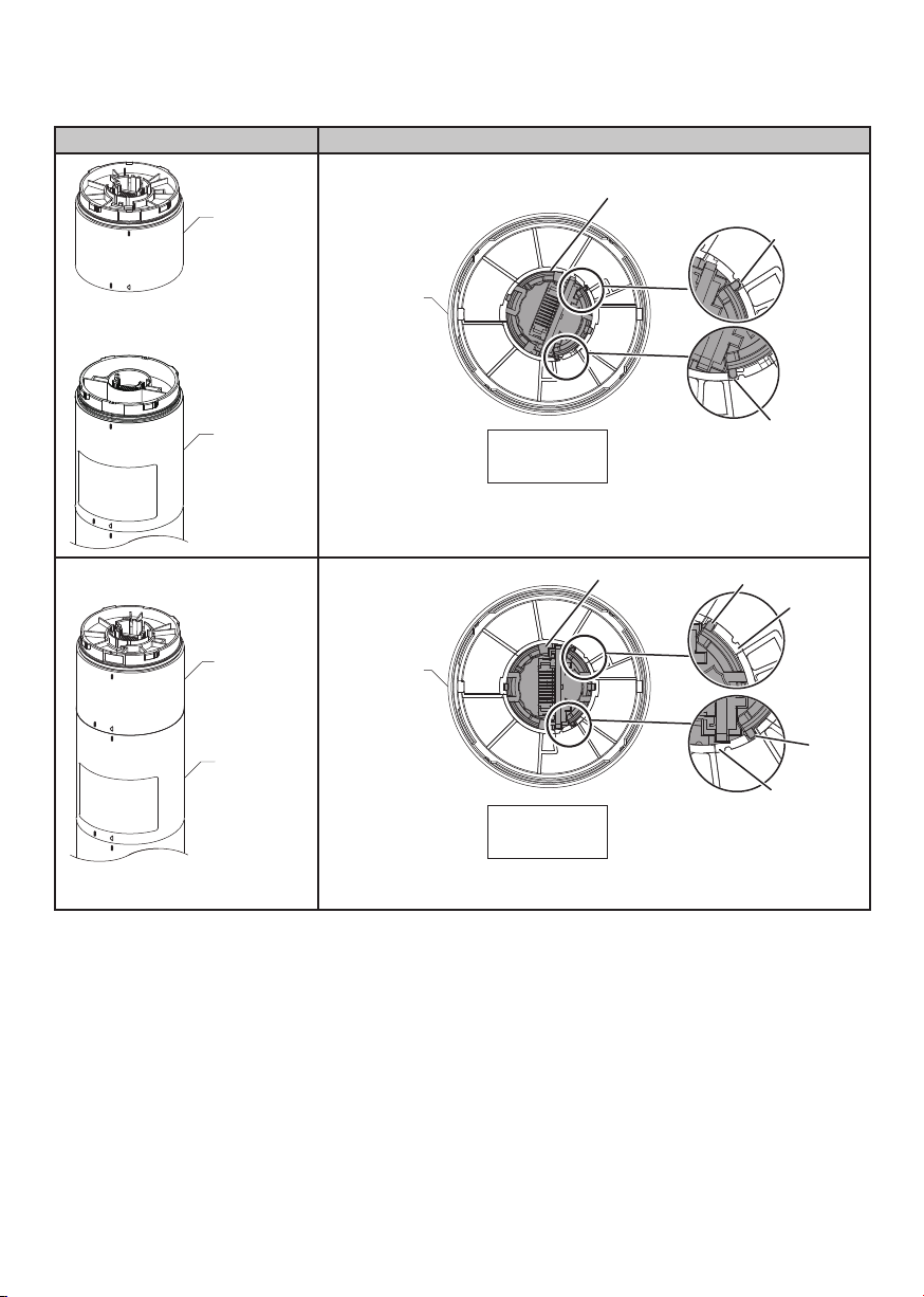
<Troubleshooting the LED Unit>
The structure of the LED Unit is indicated below.
Status Condition
LED Unit
Positioning
Mark
Lens
Rib/Groove
Body
LED Unit
Body
LED Unit
(Detached)
Top View
The rib of the lens generally fi ts into the groove when the LED Unit has been
removed from the product.
Lens
Positioning
Mark
LED Unit
(Detached)
Top View
The rib of the lens generally does not sit in the groove while the LED Unit is
attached to the product.
Rib/Groove
Rib
Groove
Rib
Groove
– 19 –
Page 20
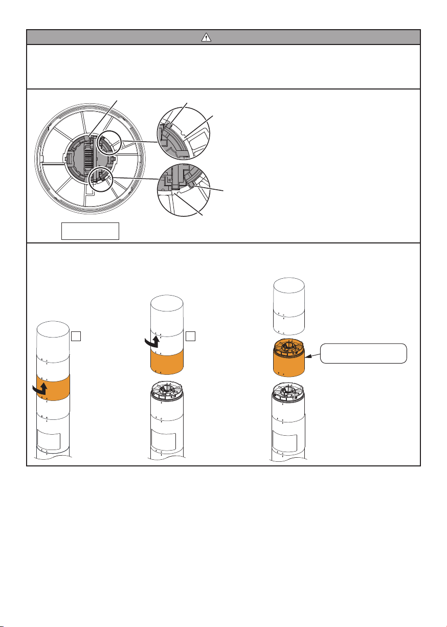
Caution
Check whether the rib of the lens inside of the LED Unit fi ts into the groove if the LED Unit does not attach properly. Attach
the LED Unit by referring to the next page if the rib does not fi t into the groove as shown in the diagram below.
In addition, the rib may slide out of the groove during removal as shown in the diagram below depending on how the LED
Unit is removed.
Attaching the LED Unit to the product again in this state may result in damage.
Lens
Rib
Groove
Rib
LED Unit
Top View
Do not remove the LED unit as shown in below.
The rib of the lens will slide out of the groove.
Attaching the LED Unit to the product again in this state may result in damage.
1 Remove multiple
LED units at the
same time.
Groove
2 Remove the target LED
Unit from the multiple
LED Units that have
been removed.
The rib of the lens slides
out of the groove.
– 20 –
Page 21
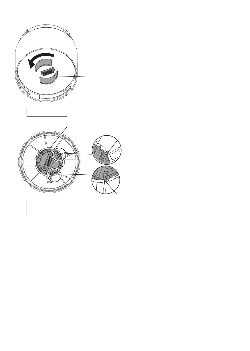
Use the procedure below if the LED Unit does not attach properly.
Turn the lens inside the LED Unit in the counter-clockwise
direction.
Turn until the lens snaps in place, and then attach the LED
Unit to the product.
Lens
LED Unit
Bottom View
Lens
Rib/Groove
LED Unit
(Attachable Status)
Top View
Rib/Groove
– 21 –
Page 22
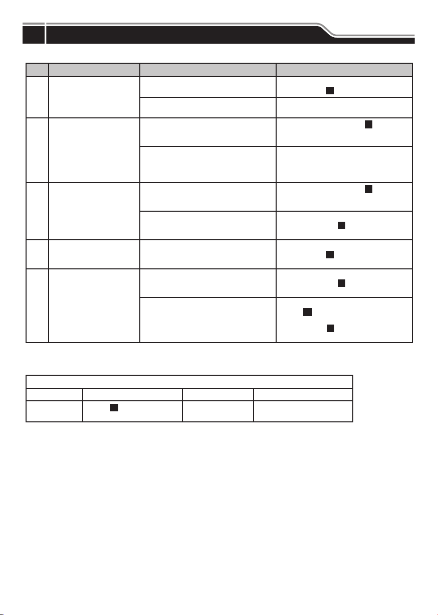
Troubleshooting
9
Troubleshoot problems that occur by following the instructions in the table below.
No. Problem Confi rmation Remedy
Wire the LED again while referring to the
instructions in “
Check whether the connected IO-Link is
putting out the proper voltage.
Refer to the instructions in “ 6 How to
Use” (p. 7-8). and resend the
processing data.
Send processing data compatible with the
color selected in the control instead of the
light color for the independent color
control unit.
Refer to the instructions in “
Use” (p. 7-8). and resend the
processing data.
Specify the parameters while referring to
the instructions in “ 6 How to Use”
(p. 7-8).
Adjust the volume while referring to the
instructions in “
(p. 9).
Send the process data while referring to
the instructions in “
(p. 7-8).
The Buzzer Unit is an optional part.
Check “12 Optional Parts” (p. 27), and
then attach the Buzzer Unit to the product
by referring to “
(p. 10-21).
5 Wiring” (p. 6).
7 Buzzer Settings”
8 Detaching the Unit”
The LED does not light.
1
The color of the LED
differs from the desired
2
color.
The LED does not fl ash.
3
The sound of the buzzer
4
is low.
The buzzer does not
5
sound.
Has the wiring been connected properly?
Is the power source supplying the proper
voltage and current?
Is the processing data correct?
Is a custom independent color control unit
being used?
Is the processing data correct?
Are the parameters correct?
Are the volume settings for the buzzer too
low?
Is the processing data correct?
Is the Buzzer Unit attached?
6 How to
6
How to Use”
Check the “Information for Inquiries,” and then contact the nearest PATLITE Sales Representative if you cannot resolve the
problem even after the above troubleshooting.
Information for Inquiries
Product Name IO-Link Signal Tower Date of Purchase / /
Model
2 Model Number
(→
Confi guration [p. 2])
Problem
Please provide as much detail
as possible.
– 22 –
Page 23
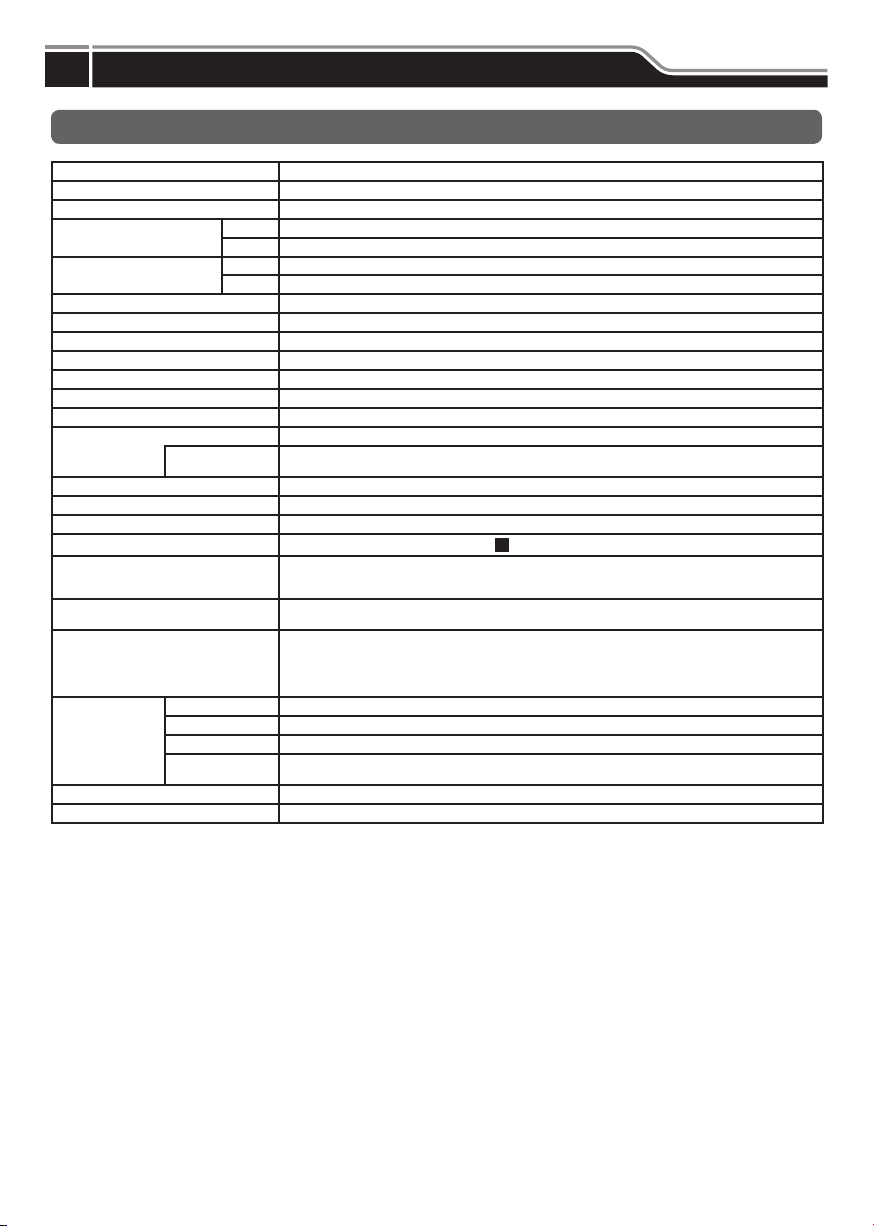
Specifi cations
10
General Specifi cations
Model LR6-3ILWMNW-RYG
Rated Voltage 24 V DC
Voltage tolerance range 18 V DC to 30 V DC
Rated current consumption
Rated power consumption
Inrush current 10 A / 0.3 msec
Ambient operating temperature -20 °C to +50 °C
Ambient operating humidity 90 % RH or less; No condensation
Ambient storage temperature -30 °C to +60 °C
Ambient storage humidity 90 % RH or less; No condensation
Installation location Indoor
Installation direction Upright direction
Protection Rating IP65, NEMA TYPE 4X, 13
Insulation resistance 5 MΩ or more at 500 V DC between charging parts and non-charging metal parts
Withstanding voltage 1 minute at 500 V AC between charging parts and non-charging metal parts
Mass (Tolerance: ±10 %) 0.38 kg
Exterior dimensions See “
Compliance standards
Notes
Function
Communication
Specifi cation
Vendor ID 763
Device ID 80001
Standard 170 mA
Maximum 200 mA
Standard 4 W
Maximum 5 W
Environmental
conditions
UL 508, CSA-C22.2 No. 14, EMC Directive (EN 61000-6-4, EN 61000-6-2)
The brightness of each LED may differ according to the characteristics of the LED or color variations in each
IO-Link revision 1.1
Transmission speed COM2 (38.4 kbps)
Minimum cycle time 8 ms
Processing data
length
When installed in the upright direction
Names and Dimensions”
3
RoHS Directive (EN 50581), FCC Part 15 Subpart B Class A
KC (KN 61000-6-4, KN 61000-6-2)
individual LED or the product.
- LED control
- Buzzer control
- Operational mode/pattern settings
- LED fl ashing/intermittent
- Buzzer Pattern Settings
6 byte / 0 byte (input from master / output to master)
The requirements in each law and regulation are only included in the language designated by each law and regulation.
Check the instruction manuals published in each language.
– 23 –
Page 24
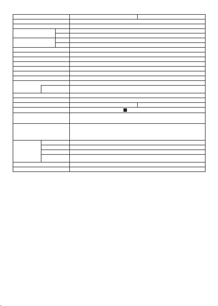
Model LR6-ILWMNW LR6-ILWCNW
Rated Voltage 24 V DC
Voltage tolerance range 18 V DC to 30 V DC
Rated current consumption
Rated power consumption
Inrush current 10 A / 0.3 msec
Ambient operating temperature -20 °C to +50 °C
Ambient operating humidity 90 % RH or less; No condensation
Ambient storage temperature -30 °C to +60 °C
Ambient storage humidity 90 % RH or less; No condensation
Installation location Indoor
Installation direction Upright direction
Protection Rating IP65, NEMA TYPE 4X, 13
Insulation resistance 5 MΩ or more at 500 V DC between charging parts and non-charging metal parts
Withstanding voltage 1 minute at 500 V AC between charging parts and non-charging metal parts
Mass (Tolerance: ±10 %) 0.2 kg 0.16 kg
Exterior dimensions See “
Compliance standards
Function
Communication
Specifi cation
Vendor ID 763
Device ID 80001
Standard 170 mA
Maximum 200 mA
Standard 4 W
Maximum 5 W
Environmental
conditions
UL 508, CSA-C22.2 No. 14, EMC Directive (EN 61000-6-4, EN 61000-6-2)
IO-Link revision 1.1
Transmission speed COM2 (38.4 kbps)
Minimum cycle time 8 ms
Processing data
length
When installed in the upright direction
Names and Dimensions”
3
RoHS Directive (EN 50581), FCC Part 15 Subpart B Class A
KC (KN 61000-6-4, KN 61000-6-2)
- LED control
- Buzzer control
- Operational mode/pattern settings
- LED fl ashing/intermittent
- Buzzer Pattern Settings
6 byte / 0 byte (input from master / output to master)
The requirements in each law and regulation are only included in the language designated by each law and regulation.
Check the instruction manuals published in each language.
– 24 –
Page 25
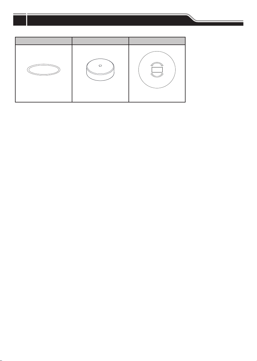
Service Parts
11
These are the various parts for the customer to use when repairing or replacing parts for the product.
O-ring 60 Head Cover 60 [W/A] Shading Sheet 60
5 pcs. 5 pcs.
– 25 –
Page 26
Optional Parts
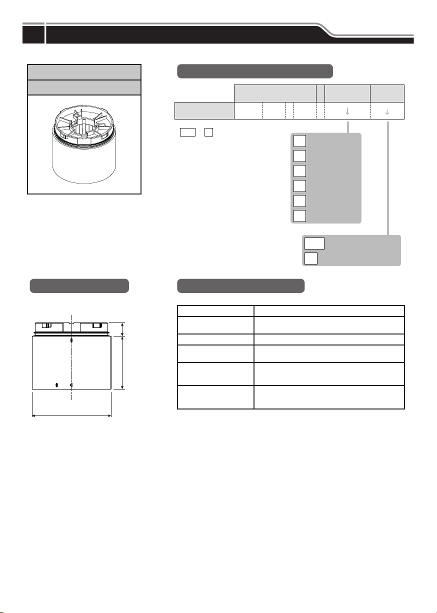
12
The optional parts for this product are listed below. (Top line: Part Name; Bottom: Model)
LED Unit
LR6-E
External Diagram
(Unit: mm)
ij
(10)
40
Model Number Confi guration
Red
Amber
Green
Blue
White
Multicolor*
Colored Globe
(None)
Clear Globe
Z
LED Unit
Color
Model Number
*
-
LR6
Model
LR 6 - E -
Z
R
Y
G
B
C
M
General Specifi cations
Model LR6-E-□□
Ambient operating
temperature
Ambient operating humidity 90 % RH or less; No condensation
Mass
(Tolerance: ±10 %)
Compliance standards
Notes
EMC Directive (EN 61000-6-4, EN 61000-6-2)
The brightness of each LED may differ according to the
characteristics of the LED or color variations in each
individual LED or the product.
-20 °C to +50 °C
0.060 kg
UL508, CSA-C22.2 No. 14
RoHS Directive (EN 50581)
Globe
Color
– 26 –
Page 27
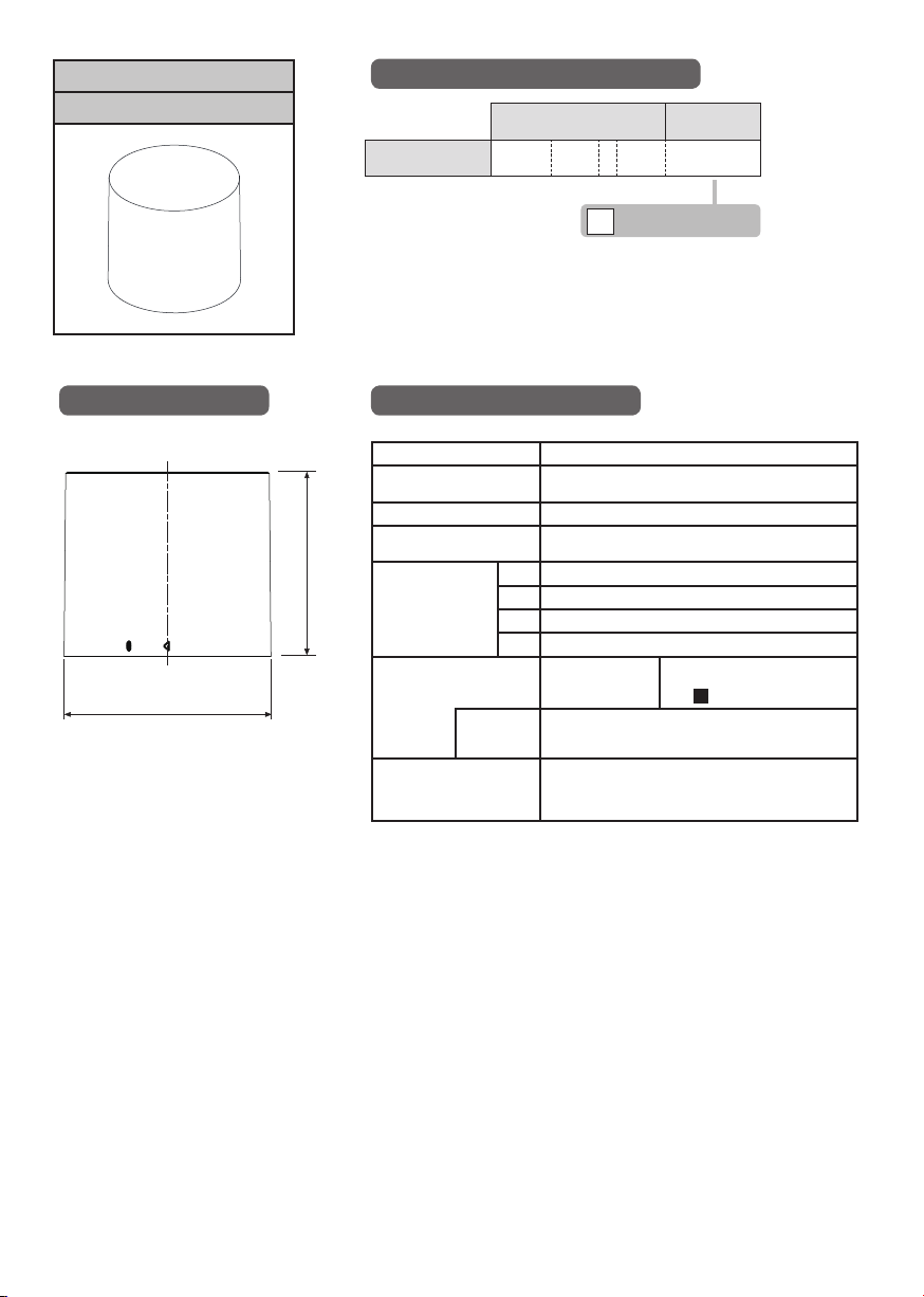
Buzzer Unit
LR6-BW
Model Number Confi guration
Model
Model Number
LR 6 - B W
Off-white (PC)
W
Body Color
(Material)
External Diagram
(Unit: mm)
ij
53.5
General Specifi cations
Model LR6-BW
Ambient operating
temperature
Ambient operating humidity 90 % RH or less; No condensation
Mass
(Tolerance: ±10 %)
No. 1 Rapid intermittent beep (call sign) / 3378 Hz
Buzzer sound/
frequency (typ.)
Sound pressure level Typ. 84 dB
Compliance standards
No. 2 Continuous beep sound / 3378 Hz
No. 3 Rapid hi-low / 2016 Hz & 3012 Hz
No. 4 Sweep sound / 1000 Hz - 4032 Hz
Environmental
conditions
Buzzer sound: No. 4 Sweep sound measured from a
distance of 1m in a total circumference from the buzzer
EMC Directive (EN 61000-6-4, EN 61000-6-2)
-20 °C to +50 °C
0.060 kg
Noise reduction approx. -10 dB
Toggle with DIP switch
See “
Buzzer Settings”
7
source.
UL508, CSA-C22.2 No. 14
RoHS Directive (EN 50581)
FCC Part 15 Subpart B Class A
– 27 –
Page 28
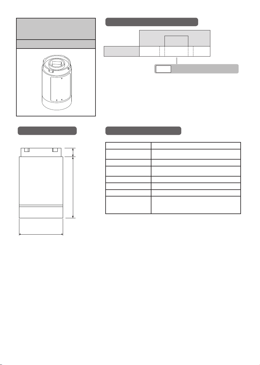
Wireless Data
Communication System
Transmitter
WDT-6LR-Z2
Model Number Confi guration
Model Number
Model
WDT - 6LR - Z2
Compatible
Product
LR Model Signal Tower Size: Φ60
6LR
External Diagram
(Unit: mm)
ij
General Specifi cations
Model WDT-6LR-Z2
10
70
Ambient operating
temperature
Ambient operating humidity 85 % RH or less; No condensation
Mass
(Tolerance: ±10 %)
Communication standard IEEE 802.15.4 (Wireless communication)
Communication frequency 2405 MHz to 2480 MHz (16 channels)
Communication distance Estimated to be approx. 30 m (Reference value)
Compliance standards
EMC Directive (EN 55032 , EN 55024), EN 60950-1
-20 °C to +50 °C
0.085 kg
UL508, CAN/CSA-C22.2 No.13-14
RoHS Directive (EN 50581)
FCC Part 15 Subpart B Class A
– 28 –
Page 29
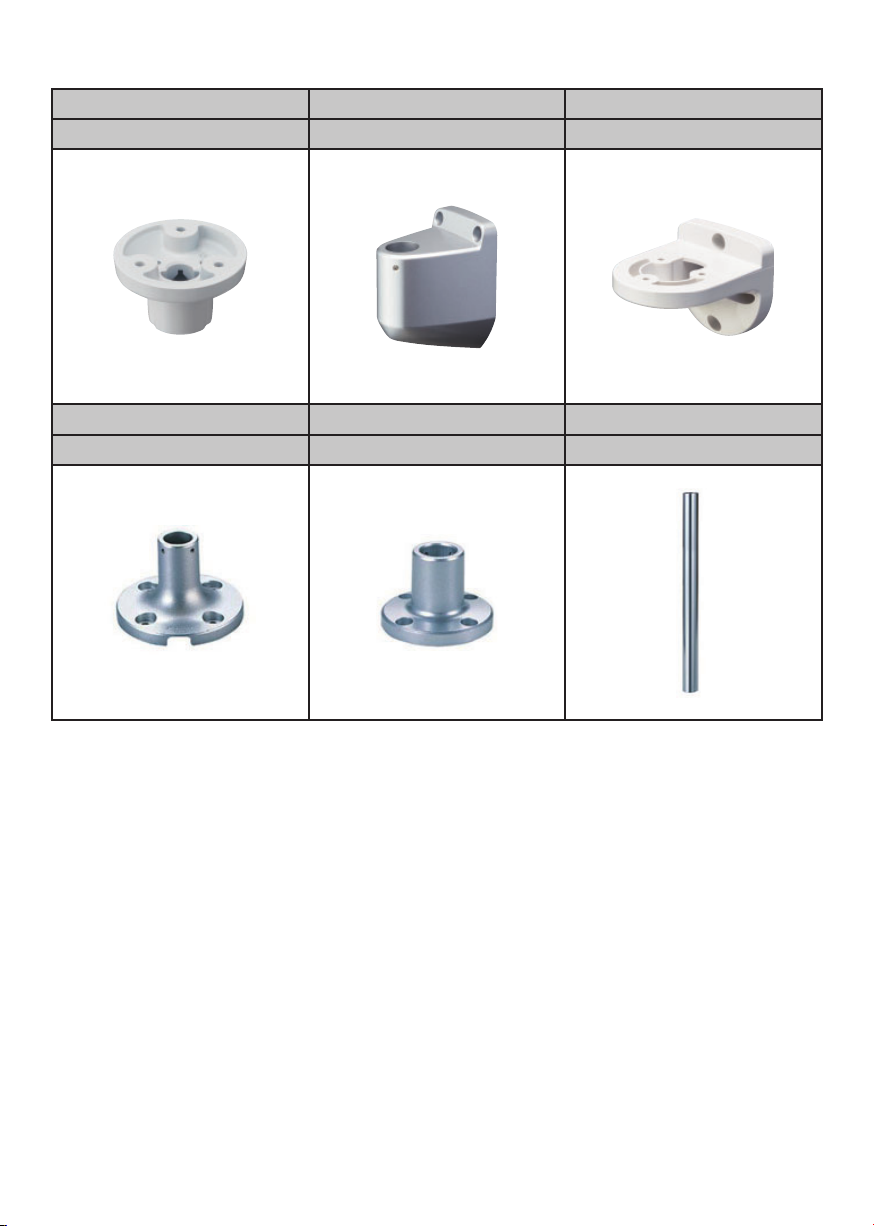
The optional parts for attachment are listed in the following table:
Pole Bracket Wall Mounting Bracket Wall Mounting Bracket
SZP-004W SZK-001U SZK-003W
Mounting Bracket Mounting Bracket Aluminum Pole
SZ-010 SZ-016A POLE-[100/300/800]A21
– 29 –
 Loading...