

Page 1
LP8US LED Surface Mount Warning Light
INSTALLATION MANUAL
Thank you for purchasing PATLITE’s LED Warning Light for your application. Please read these
instructions carefully before installation, maintenance and repair. Store this manual in a safe
place for future reference. If you have any questions regarding this product, please contact your
PATLITE sales representative.
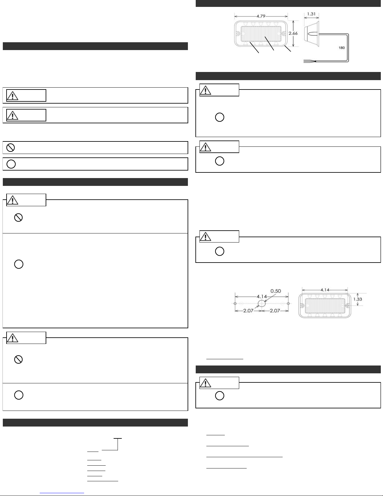
3. Part Names and Dimensions
NOTICE FOR SAFE OPERATION
In order to prevent injury to the user and other personnel or damage to assets, note the
following:
The warning indications are divided into the following classes according to the
degree of danger or damage incurred when the warning is not taken into
consideration and the product is not correctly used.
Warning
Caution
The following symbols explain the nature of the information to be observed.
Described action is strictly prohibited. It is not to be carried
circumstances.
Described action is “enforced.”
!
Failure to follow these instructions may lead to death or serious
injury.
Failure to follow these instructions may lead from slight to
medium injury or lead to property damage or injury to others.
out under any
It should be carried out by all means.
1. To operate this product safely, please observe the following:
Warning
(Prohibited)
!
(Enforced)
Caution
(Prohibited)
!
(Enforced)
Do not substitute any parts from other products or disassemble
this unit. It may cause malfunction or failure.
After installing this product, be careful not to use this product to
climb onto a machine or to get anything snagged onto this product
while it is mounted on equipment, etc. Failure to comply may result
in falling off the machinery or product damage may occur.
Be sure to disconnect the power when wiring, mounting,
exchanging, or repairing the product. Failure to comply may result
in damage of the internal circuitry and the danger of electric shock
due to short-circuiting.
Request the installation and wiring to be accompanied by a
professional contractor. Failure to comply may result in electric
shock, fire or falling from high places.
When this product is used for security purposes, it should be
inspected daily. In addition, it is recommended that other security
products be used together with this product in case the product
malfunctions.
After installing this product, be careful not to use this product to
climb onto a machine or to get anything snagged onto this product
while it is mounted on equipment, etc. Failure to comply may result
in falling off the machinery or product damage may occur.
Verify the installation location is a firm location which can handle
the weight of the product.
Do not loosen any screws on the assembly. It will have an adverse
effect on the protection rating.
In order to avoid danger to the eyes, do not stare into the beam, do
not view directly into the optical instrument, do not aim the beam
toward someone’s eyes. The LED beam is hazardous to the eyes.
The designated hardware should be used for installation. Any parts
used that are not specified may result in product damage or
personal injury.
Do not connect this device to a strobe power supply. This product
is self-contained and does not require an external strobe power
supply.
Verify that the specified operating voltage is not exceeded.
For safety measures, be sure to connect an external fuse to protect
this product from damage from overcurrents and overvoltages,
mis-wiring, etc.
Lens
Body
(inches)
Gasket
Control Cable
4. Installation
Warning
To prevent electrocution, disconnect power prior to mounting or
performing maintenance. Failure to comply may result in electric
shock or fire.
!
(Enforced)
To prevent galvanizing of two dissimilar metal surfaces, the
rubber gasket must be installed between the mounting surface
and the light body.
Be sure to install the plastic washer first on each mount screw.
Caution
!
(Enforced)
Installation Procedure:
Find the following items provided with the light unit:
•2 each: #8 x 7/8”
•2 each: #8 plastic washers
•2 each: #8 x ½”
•2 each: #8 metal washers
•2 each: #8 hex nuts
•1 each: Gasket
Use extra caution to prevent this product from falling during
installation.
self-tapping screws
machine screws
Caution
Do not over tighten the mounting screws or nuts. This could
!
(Enforced)
Locate a flat surface on which to mount your LP8US unit.
Using the dimensional drawings below, measure and drill pilot holes for the two
mounting screws as well as the ½”
through.
(inches)
Make sure to de-burr any rough edges of the ½”
Insert the control cable through the gasket, then through the ½”
center. Align the unit and gasket.
Use either the machine screws or the self-tapping screws as chosen for this installation.
Install the plastic washer first, next to the screw head.
Finish the mounting by tightening the screws and/or washers and nuts as applicable.
Do not over-tighten
cause permanent damage to the mounting surface and
hardware.
diameter hole on center for the cable to pass
hole so the cable will not be damaged.
diameter hole on
!
5. ID Number Selection
Caution
!
(Enforced)
DO NOT connect this device to a strobe power supply!
2. Model Number Configuration
L P 8 U S –
Color:
R : Red
Y : Amber
G : Green
B : Blue
C : Clear (White)
-1-
R
First, depending on the Operation Mode desired you will need to set the ID
Number for each LP8US unit as applicable.
One Light: For operating the LP8US unit by itself or independently of other lights, set the
ID Number to 1.
Alternating Two Lights
Number of one unit to 1; set the ID Number of the other unit to 2.
Simultaneous Two, Three or Four Lights
same pattern Set the ID Number of all units to 1.
Four Lights X-Pattern
pattern. Set the ID Number of each unit: Set unit 1 to ID #1; unit 2 to ID#2; unit 3 to
ID#3; unit 4 to ID#4.
As you can see from the Pattern Table in Section 6, not all patterns are available for
certain Operation Modes.
: For operating two LP8US units to flash back and forth, set the
: For operating 2-4 LP8US units to flash the
: Four LP8US units can be arranged physically so they flash an “X”
-2-
ID
Page 2
5. ID Number Selection (continued)
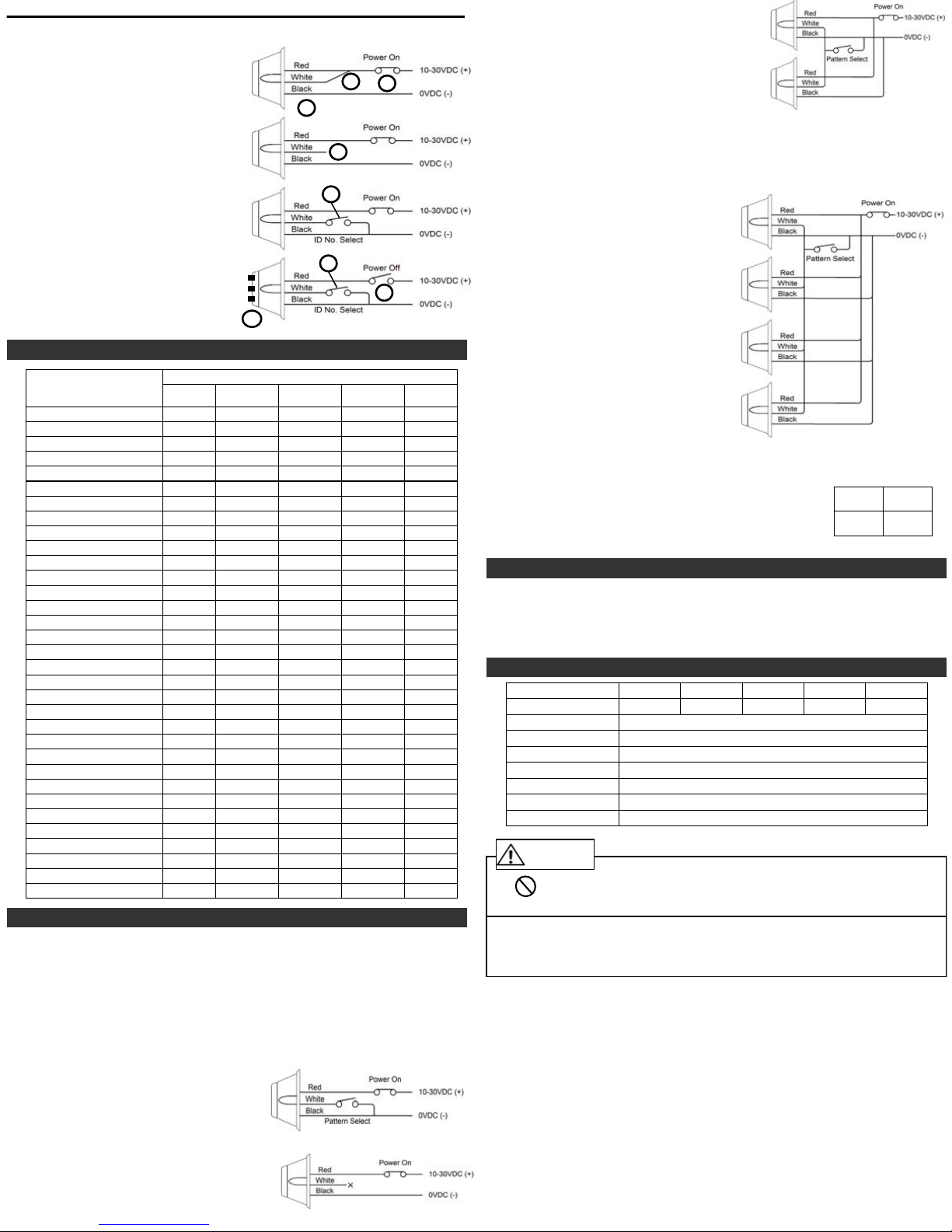
The procedure for setting the ID Number of each LP8US unit is below.
1.Temporarily connect RED and WHITE..
2.
Apply DC10-30V: + on RED and WHITE, on BLACK
3.
When the LP8US unit is powered, the ID
Select Mode is set.
4.
Disconnect the WHITE wire while leaving
1
2
Power On = ID Setting Enabled
3
the power on the RED wire.
5.Each momentary connection of WHITE
and BLACK will cause the unit to cycle
4
through ID numbers 1, 2, 3 & 4, then
back to 1.
6.For each momentary connection, the
5
light will flash the no. of times
corresponding to the ID number
currently selected.
7.
Stop at the ID number desired for this
unit.
8.Disconnect power to exit the ID Select
Mode.
3 Flashes = ID#3
7
6
8
6. Light Pattern Table
X
X
X
X
X
X
X
X
X
X
X
X
X
X
X
X
X
X
X
X
X
X
X
X
X
X
X
X
X
X
X
Operating Mode
Simultaneous
2 - 4 Lights
X
X
X
X
X
X
X
X
X
X
X
X
X
X
X
X
X
X
X
X
X
X
X-Pattern
4 Lights
X
X
Pattern Name
1. Quint
2. Warp
3. Inter-cycle Flash
4. Double Flash
5. Quad Flash
6. Power Pulse
7. Road Runner
8. Q-Switch
9. Road Runner Steady Burn
10. Quad Steady Burn
11. E-Ideal Single Flash
12. E-Ideal Double Flash
13. Quad-2 Flash
14. Double-2 Flash
15. X-Warp
16. X-Double
17. Power Runner
18. LCR Quint
3
19. Warp
20. Ultra Warp
21. Thunder & Lightning
22. Lite Speed
23. SuperSonic
24. LCR Lite Speed
25. SuperSonic Ultra
26. Tempo Shift
27. Tempo Shift Warp
28. SBE2
2
29. C
2
30. U
31. Ultra Glow
32. Cyclone
33. Chameleon
1 Light
X
X
X
X
X
X
X
X
X
X
X
X
X
X
X
X
X
X
X
X
X
X
X
X
X
X
X
X
X
X
X
Alternating
2 Lights
7. Pattern Selection & Wiring
Once the ID Number for each unit is set, they may be wired for operation
according to the Operating Mode selected for the application.
Decide if you want to have a Pattern Select switch available. This may be useful if
you plan to switch patterns often.
If you are not using a Pattern Select switch, be sure to insulate the white wire when
finished, to prevent unexpected pattern changes if the wire accidentally shorts to
ground (-).
For all multiple-unit operations, select the same pattern for each unit before wiring.
This procedure is the same as for the One-Light Operating Mode.
1. Operation as a single unit:
Set the ID number to 1 (See Section 5).
Momentarily connect WHITE to BLACK.
Repeat until desired pattern is found.
From now on, this pattern will show each time you connect power to the unit.
If you leave a Pattern Select switch connected,
you can change patterns often if required.
If you don’t leave a pattern select switch
connected, be sure to insulate the white wire.
Flashes
Per Minute
70
350
70
80
180
113
113
80
200
146
67
95
545
85
170
67
200
176
2. For operation of 2 units alternating:
Set the ID of one unit to ID#1
and the second unit to ID#2
(See Section 5).
For each unit, momentarily connect WHITE to
BLACK. Repeat until desired pattern is found.
Set each unit to the same pattern.
Connect the same color wires of unit 1 and unit 2; RED to RED, WHITE to WHITE
and BLACK to BLACK. Now when you sequence through the patterns with the
Pattern Select switch as shown below, both units will show the same pattern.
Stop sequencing when you see the pattern you want. After this, the lights will flash this
pattern when power is applied.
3. For operation of 2 -
4 units simultaneously:
Set the ID of all units to 1 (See Section 5).
For each unit, momentarily connect
WHITE to BLACK. Repeat until desired
pattern is found. Set each unit to the
same pattern.
Connect the same color wires of all units;
RED to RED, WHITE to WHITE and BLACK
to BLACK.
Now when you sequence through the
patterns with the Pattern Select switch as
shown, all units will show the same
pattern.
Stop sequencing when you see the pattern
you want. After this, the lights will flash
this pattern when power is applied.
4. For operation of 4 units as an ‘X-Pattern’:
Set the ID of 4 units as ID#1, ID#2, ID#3, and ID#4 (See Section 5).
For each unit, momentarily connect WHITE to BLACK. Repeat until desired pattern
is found. Set each unit to the same pattern (Pattern 15 or 16 per the table in Section
6) on each unit.
Connect the same color wires of each unit; RED to RED, WHITE
to WHITE and BLACK to BLACK as in section 3 above
Arrange unit placement as shown:
Sequence is 1 –
4 –
2 –
3.
ID#4 ID#2
ID#3 ID#1
Unit Arrangement
8. Slave Mode
The LP8US is capable of being activated through the use of a user-supplied flasher by
putting the unit in Slave Mode.
Permanently connect the WHITE and BLACK wires to 0V (-).
Connect the RED wire through a 5A fuse to the output of a DC10V-30V switching
flasher.
9. Specifications
Model Name LP8US-R LP8US-Y LP8US-G LP8US-B LP8US-C
LED Color *
Rated Voltage
Current Consumption
Overall Dimensions
Number of Flash Patterns
Number of LEDs
Light Sync Technology
Operating Temp. Range
(L) x (W) x (D) = 4.79” x 2.66” x 1.31” (122mm x 68mm x 33mm)
-40OF ~ +149OF (-40OC ~ +65OC)
* Due to the inherent properties of LEDs, variations of color and hue may occur.
GreenAmberRed Blue White
DC10V ~ DC30V
1.1A
33
8 (Generation 3)
Yes
Caution
The LP8US is a factory-sealed unit that CANNOT be serviced in the
field. Any attempt to gain access to the LP8US unit will most likely
(Prohibited)
PATLITE Corporation disclaims all liability for any malfunction or damage that occurs as
a result of handling contrary to the instructions, cautions and warnings mentioned in
this manual.
Specifications may change without notice due to continual product improvement.
Limited Warranty:
PATLITE (U.S.A) CORPORATION ("PATLITE") warrant its products to be free from defects in
material and workmanship under normal and proper use for a period of one (1) year from the
initial date of shipment by PATLITE. In the even of a defect not caused by misuse or damage
to the products, PATLITE will, at its option, repair, replace or return the purchase price for,
defective products upon PATLITE's inspection. THIS WARRANTY IS IN LIEU OF AND
EXCLUDES ALL OTHER WARRANTIES, REMEDIES AND CONDITIONS, WHETHER
EXPRESS, IMPLIED OR STATUTORY, INCLUDING WITHOUT LIMITATION ANY IMPLIED
WARRANTIES OF MERCHANTABILITY AND FITNESS FOR A PARTICULAR PURPOSE. IN
NO EVENT SHALL PATLITE OR THE MANUFACTURER BE LIABLE FOR ANY SPECIAL,
INCIDENTAL OR CONSEQUENTIAL DAMAGES, INCLUDING LOSS OF PROFITS OR
"DOWN TIME" DAMAGES, WHETHER ARISING FROM N EGLIGENCE, TORT, STRIC T
LIABILITY, CONTRACT, WARRANTY OR OTHERWISE. IN NO EVENT SHALL PATLITE OR
THE MANUFACTURER BE LIABLE FOR PUNITIVE OR EXEMPLARY DAMAGES.
PATLITE (U.S.A.) Corporation 20130 S. Western Avenue Torrance, CA 90501
TEL: 888-214-2580 FAX: 310-328-2676 Web Site: www.patlite.com Sales: [email protected]
cause permanent damage and will void its warranty.
-4--3-
 Loading...