

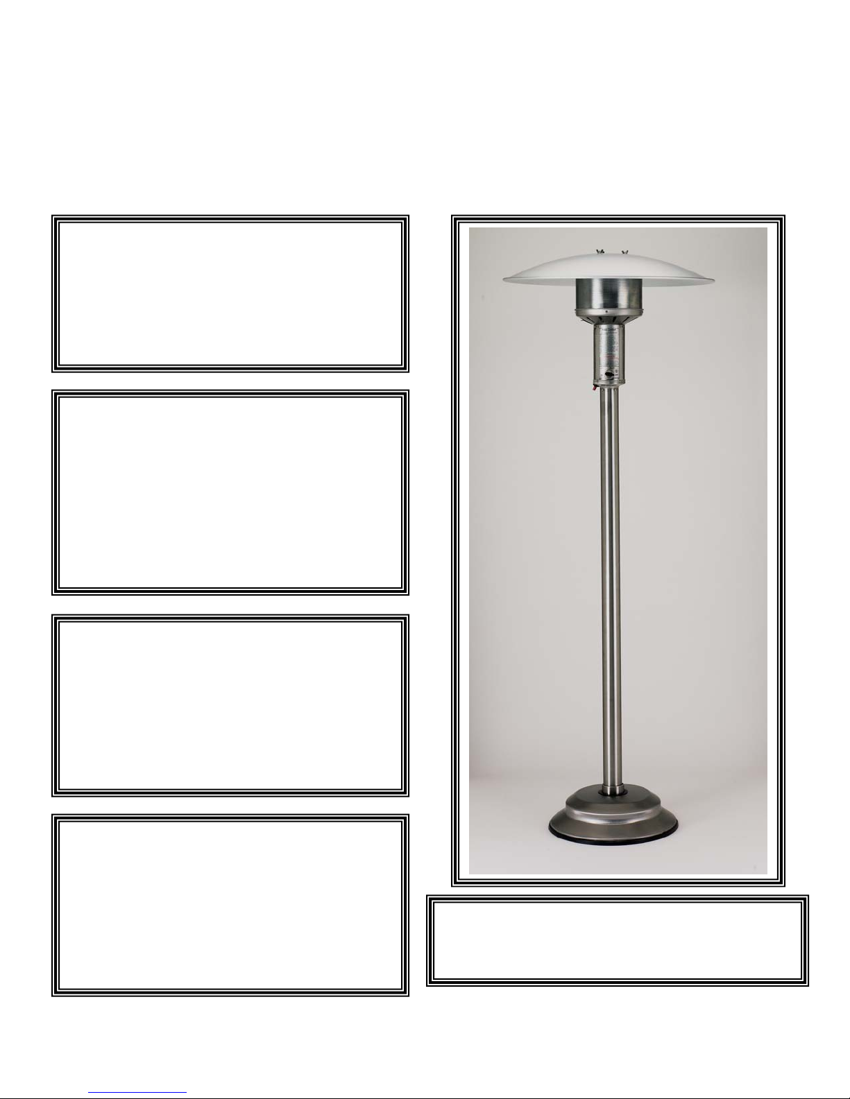
PATIO COMFORT
g
NATURAL GAS FUELED OUTDOOR PATIO HEATER
MODEL NPC05
ASSEMBLY INSTRUCTIONS
CARE, USE, AND SAFETY MANUAL
Do not store or use gasoline
or other flammable vapors or
liquids in the vicinity of this or
any other appliance.
Please read these assembly instructions
carefully before attempting to assemble,
use, or service this product. Please
keep this manual for your future
reference. If you have any questions,
please feel free to call us at 949-4743070 Monday through Friday 7AM to
4PM Pacific Time.
Improper installation, adjustment,
alteration, service or maintenance of
this product can cause injury or
property damage. Please read the
installation, operating, and maintenance
instructions thoroughly before installing
or servicin
FOR YOUR SAFETY!
IMPORTANT!
General Hazard Warning:
this appliance.
Please read all operating instructions
before using and operating this appliance.
Always follow the correct lighting and
usage procedures.
Please handle metal parts with care to
avoid injury. Please follow all steps as
outlined.
Never allow children to use this product!
© AEI CORPORATION 2005
WARNING:
This product is for Outdoor Use Only
Revised 7-06-05 gfs
1

1. The assembly and installation of this appliance must conform with local codes or in the
absence of local codes, to the National Fuel Gas Code ANSI Z223.1-1988.
2. There must be adequate clearances around all air openings into the combustion
chamber. You must also have adequate clearances from combustible materials and an
adequate air supply going to the heater. See page 19 for specific clearances from
combustibles.
3.
A HIGH QUALITY NATURAL GAS REGULATOR, DOUBLE QUICK
DISCONNECT COUPLER, AND 12 FOOT HOSE SET WITH SAFETY SHUT
OFF VALVE HAS BEEN PROVIDED FOR YOUR SAFETY AND
CONVENIENCE. THE REGULATOR HAS BEEN PRE SET TO OPERATE
YOUR HEATER AT 4.5” WATER COLUMN. ALL OF THESE COMPONENTS
MUST BE USED FOR THE SAFE OPERATION OF YOUR HEATER. DO NOT
ATTEMPT TO REPLACE, MODIFY, OR ALTER THE COMPONENTS
PROVIDED WITH YOUR HEATER
4. The maximum inlet supply pressure CANNOT EXCEED 10” W.C. natural gas.
.
5. Test all fittings and connections with a soapy solution prior to use. Never use an
open flame or open flame device.
6. Certain items or materials when stored under the heater or too close to the heater head
will be subject to radiant heat that could cause these items to be damaged.
7. Please review carefully and follow all assembly instructions as shown from pages 11 –
16. If you do not understand any of these instructions or feel uncomfortable assembling
your unit please call your selling dealer or call us directly at 949-474-3070.
8. Please carefully inspect the rubber hose included with the unit before each use. Be sure
there are no visible cracks, damage, abrasion, or other signs of visible wear. If the
hose, quick connect couplers, or main shut-off valve appear to have any problem
whatsoever they should be replaced with a genuine Patio Comfort replacement part.
9. When using your heater with 12-foot hose please be sure that the hose is placed in a
manner where it cannot be damaged or positioned in a way that someone might trip
over it.
10. Please follow the lighting and shutdown instructions on page 20- 21 to insure safe use.
© AEI CORPORATION 2005
2

Please note the following very important safety precautions:
!!! Children and adults should be alerted to the hazards of high surface temperatures of
the main burner and reflector and should stay away from these areas.
!!! Children should be carefully supervised when near the heater. This heater is not a
toy and children should not be allowed to push, climb on, or swing on the heater.
THESE ACTIONS COULD CAUSE SERIOUS INJURY, PROPERTY DAMAGE, OR
DEATH.
!!! Clothing or other flammable materials should not be hung from the heater and/or
placed near the heater during operation.
!!! Installation and repair of the heater should be done by a qualified service technician.
The heater should be visually inspected before each use and at least annually by a
qualified service technician. Certain weather conditions such as being near the
ocean, dusty areas, areas with high humidity, areas with high wind conditions, and
heavy use, may require more frequent cleaning or maintenance. When in doubt call a
qualified service technician. It is imperative that the control compartment, burner
system, and circulating air passages of the heater be kept clean.
!!!
Any part, sub-assembly, or component removed for cleaning or maintenance must be
properly re-installed before using the heater.
Some basic use and maintenance instructions:
!!! Be sure to keep the area where the appliance is being used free from combustible
materials, gasoline, and other flammable materials.
!!! Please be sure there are no obstructions near the heater head.
!!! The appliance is operating properly when there is a nice cherry red glow (seen better
at night) coming from the emitter grid starting two to three inches from the bottom of
the emitter grid. Wind gusts will affect and possibly disrupt the glow and flame
pattern. The heater should not be operated in windy conditions over 5 – 7 MPH. If
you can protect the heater from wind gusts it will operate far more efficiently.
Operating the unit in severe wind or dusty conditions will affect the burning
characteristics, may create soot on the emitter grid and burner, and possibly clog the
pilot or main burner orifices.
!!! The heater post, base, and reflector, may be cleaned with basic soap and water and
mild household cleaning products, car wax, or commercially available
cleaners. Never attempt to clean the emitter grid radiant with any cleaning solutions
or abrasive materials. Never spray the emitter grid or heater head assembly with
water or other liquids, as it will damage the radiant, burner, valve, and ignition
system. These parts are constructed of commercial quality stainless steel and brass
and require no cleaning
small non-abrasive brush to remove excess soot that may have accumulated on the
emitter. If the emitter
and clean the burner head as well.
. Occasionally, you can gently brush the emitter grid with a
grid shows sooting you may have to remove the emitter grid
stainless steel
!!! It is absolutely imperative that this heater only be used OUTDOORS and in a
well-ventilated space and shall not be used in a building, garage, motor vehicle,
recreational vehicle, boat, tent, or other enclosed areas. This is an un-vented heating
product and creates by-products of combustion that can cause injury and possibly
death.
© AEI CORPORATION 2005
3

The preceding pages attempt to highlight only the most important safety aspects and
guidelines for using your natural gas fueled Patio Comfort heater. We have made every
effort to thoroughly address all safety, assembly, lighting, and use issues for this product
in the manual to follow. We strongly encourage that you read and understand the
materials contained in the manual before using your heater. If you have any questions
whatsoever regarding the safe assembly or use of your heater please call your Patio
Comfort Dealer or Authorized Distributor or call us directly at 949-474-3070.
Thank you
very much for purchasing a Patio Comfort Patio heater. This manual contains very
important information detailing the proper assembly, operation, and maintenance of this
product. This product has been designed with the latest in safety technology, but it is
important to remember that this is a heating appliance and some of the surfaces are extremely
hot to the touch and can cause bodily injury. Important safety information is presented
throughout this manual for your safety and that of your family. We have designed this product
to provide you with many years of outdoor comfort when operated and maintained properly. If
you have questions as to the assembly or safe operation of the heater please call your selling
dealer or call us directly 949 474-3070 Monday through Friday & 7 AM to 4 PM Pacific Coast
Time.
© AEI CORPORATION 2005
4

Table of Contents
PAGE #
BASIC SAFETY AND OPERATIONAL DATA
TABLE OF CONTENTS 5
TECHNICAL DATA 6
FUNCTION OF HEATER 6
ASSEMBLY TIPS 6
PARTS DIAGRAM/DESCRIPTION (HEAD ASSEMBLY) 8
PARTS DIAGRAM/DESCRIPTION (SUB-ASSEMBLY) 9
TOOLS NEEDED 10
FASTENER IDENTIFICATION 10
ASSEMBLY INSTRUCTIONS – STEP 1 11
ASSEMBLY INSTRUCTIONS – STEP 2 TO 4 12
ASSEMBLY INSTRUCTIONS – STEP 5 TO 7 13
ASSEMBLY INSTRUCTIONS – STEP 8 TO 9 14
1
ASSEMBLY INSTRUCTIONS – STEP 10 TO 12 15
ASSEMBLY INSTRUCTIONS – STEP 13 TO 14 16
INFORMATION ON NATURAL GAS SUPPLY 18
PLACEMENT OF HEATER 19
LIGHTING INSTRUCTIONS 20
HEATER STORAGE AND INSECT WARNING 21
CLEANING AND MAINTENANCE 22
TROUBLE SHOOTING GUIDE 23
WARNINGS AND SAFETY POINTS 24
SERVICE AND WARRANTY INFORMATION 26
LEGAL RIGHTS 27
WARRANTY REGISTRATION FORM 28
© AEI CORPORATION 2005
5

Technical Data: Model NPC05
This unit is designed and configured
for use with Natural Gas Only.
Fuel : Natural Gas
Heating: Each
12 foot circle of sun like radiant heat. Heat output
will vary based on “wind chill” factor, outside air
temperatures, altitude, prevailing wind conditions,
and location of heater.
Pressure: The unit is equipped with an external
Natural Gas Regulator (supplied with heater) preset
to 4.5 Inches Water Column. This specially
designed regulator, fuel line, and natural gas
fuel source shut-off kit must be used with this
appliance. Hose, couplers, and shut-off
components are CSA (AGA) approved and should
meet all local codes and ordinances in U.S. and
Canada. Check your local codes agency if you have
any questions. Complies with ANSI Z 21.54
Maximum: pressure Natural Gas ½ psig
Minimum inlet supply pressure 6.0” W.C.
Manifold Pressure: 4.5”
BTU Input/Hour 41,000 BTU Input /Hour
Main Burner Orifice Size:
Weight: 57 Pounds
Overall Height: 90 inches 228 cm
Reflector Diameter: 34 inches or 86 cm
Ignition System: Push Button Piezo with Pilot
Flame
Fasteners: Stainless Steel
Materials: Reflector: Anodized Aluminum
Stainless Steel Heaters: Major Components:
Series 304 Stainless Base: socket, 66” post, emitter
grid, decorative sleeve, base cover plate, and
burner. Ballast Weight Powder Coated Cast Iron
Other features: 100% Safety Shut Off Valve
No Electrical Connections Required
Constant Pilot
12 Foot MB Sturgis Steel lined Hose with
integral ball valve, quick disconnect coupling
with thermal protection, and a 3/8”fully
interlocking strip-wound hose/male plug x
3/8”female quick disconnect coupling.
MAXITROL NG Regulator @ 4.5” W.C. included
Patio Comfort heater will cast a 10-
0.12 Dec. In.
Function of Heater
Infrared heaters utilize virtually 100% of the
fuel/energy they consume to produce clean draftfree warmth. Infrared heaters do not waste
precious energy by trying to heat the air.
Infrared heat works like the radiant rays of the sun
and will directly heat objects near them such as
people, tables, chairs who in turn will absorb the
heat and reflect it. The push button Piezo ignition
system is used to light the pilot flame first. After the
thermocouple device allows gas to flow to the main
burner head
burner
Setting.
After the main burner is lit the burner will radiate
heat in a 360-degree circle. The circle of warmth
will vary dependent on outdoor temperatures, wind
chill factor, area protection, and other variables.
The average heating area is approximately a 10-foot
ring of warmth. The reflector will return upwardly
radiated heat downwards. On first use please allow
heater to burn a few minutes to burn off machining
oils used in the production of the heater.
Please note:
you may then safely engage the main
system by turning valve control knob to “ON”
Upon first using the heater, not
using the heater for an extended period, or
after re-attaching the 12 foot hose to the
unit, it may be necessary to depress the
control knob at the “PILOT” setting up to
two minutes to purge the air in the hose and
fuel lines before the PILOT flame will ignite.
Please be patient, this is all part of the safety
system that has been designed for your
protection.
Assembly Tips
For your convenience and safety the Patio Comfort
outdoor patio heater has been almost completely
Assembled. The burner head and valve assembly
have been fire tested for added safety.
Assemble all nuts and bolts loosely at first. Tighten
all connections after the completion of the assembly
process. This eases your work and increases the
overall stability of the appliance. Before using the
heater please be sure to check all connections
with a solution of soap and water. More on this
later in the instructions. Never use a flame to check
for leaks!
© AEI CORPORATION 2005
6

When starting the assembly process please take all
of the parts out of the boxes and check if anything is
missing. Please check parts with the following parts
breakdown. Even though we exercise extreme
quality control procedures occasionally we will have
a missing part or a part may have been damaged in
Notes:
transit. If anything is missing, please contact your
local
Patio Comfort dealer or call us directly at
949-474-3070. We will immediately help you. The
same holds true on any questions you might have
on assembly or operation. When in doubt, please
ask. We’re at your service.
© AEI CORPORATION 2005
7
© AEI CORPORATION 2005
8

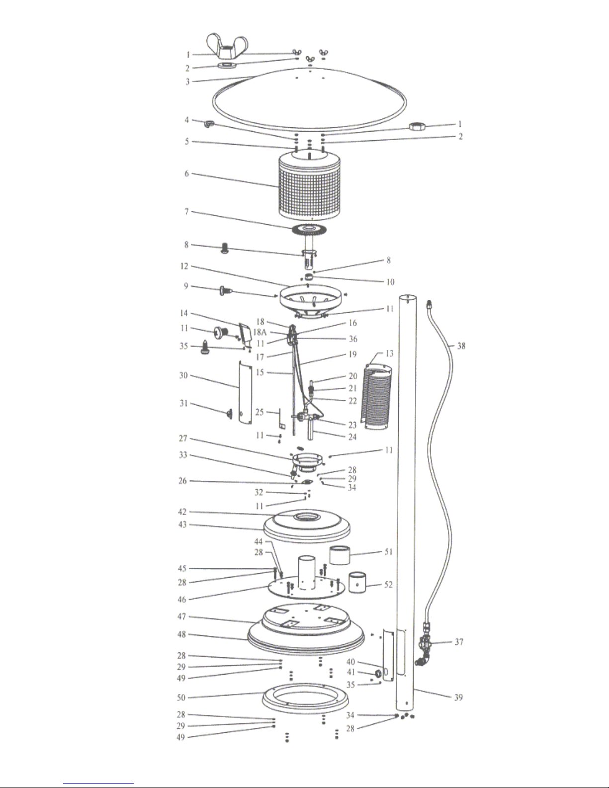
PATIO COMFORT OUTDOOR PATIO HEATER MODEL NPC05
PARTS DIAGRAM AND REPAIR PARTS
KEY PART# DESCRIPTION QTY KEY PART# DESCRIPTION QTY
1001 HEX-NUT M8 SS 3 28 1028 FLAT WASHER 6 MM DIA. SS 24
1
1001-03 W
2 1002 FLAT WASHER 8MM DIA. SS 6 30 1030
3 1003 REFLECTOR 1 31 1031 KNOB 1
4 1004 LOCK WASHER 8MM DIA. SS 3 32 1032 FLAT WASHER 5 MM DIA. SS 2
5 1005 HEX-BOLT M8 X 20MM SS 3 33 1033 PIEZO IGNITER/SPECIFIC NUT 1
6 1006 EMITTER GRID 1 34 1034 PAN HEAD SCREW M6 X 12MM 8
7 1007-05 BURNER ASSY WITH SHIELD/NO SCREEN 1 35 1035
8 1008 PAN HEAD SCREW M4 X 6 MM SS 5 36
9 1037 SELF-TAPPING SCREW M5 X 10 4 37 1137 REGULATOR FITTING ASSY. 1
10 1010 BASE FITTING FOR MAIN BURNER 1 38 1138 54”FUEL HOSE ASSY 1
11 1011 PAN HEAD SCREW M5 X 8 MM SS 17 4139 POST /ACCESS HOLE SS 1
12 1012 PAN ASSY SS 1
13 1013 PERFORATED BODY 1 4140 ACCESS PANEL/HOLE Ø22 SS 1
14 1014 PILOT SHIELD 1
15 1015 ELECTRODE 1 41 1141
16 1016 PILOT ASSY 1 42 1142
17 1017 WIRE INSULATION 1 4143 DECORATIVE COVER FOR BASE SS 1
18 1018 THERMOCOUPLE 1
18A 1018A SCREW FOR THERMOCOUPLE 2 44
19 1019 PILOT TUBE ASSY 1 45 1145 HEX-BOLT M6 X 50MM SS 4
20 1020-05 ORIFICE FOR MAIN BURNER 1 46 1146 SOCKET ASSY 1
ING-NUT M8 SS 3 29 1029 LOCK WASHER 6 MM DIA. SS 16
103605
39
5139 PAINT POST /ACCESS HOLE 1
40
5140 ACCESS PANEL/HOLE Ø22 PAINT 1
43
5143 PAINT DECORATIVE COVER FOR BASE 1
1104-
04
ACEPLATE FOR LIGHTING
F
INSTRUCTION
ELF-TAPPING PAN HEAD SCREW
S
OR PILOT SHIELD M4 X 8 MM
F
ILOT ORIFICE 1
P
B
ULK HEAD
OLDING FOR DECORATIVE
M
SOCKET
EX-BOLT M6 X 20MM SS 4
H
1
6
1
21 1021 FITTING FOR ORIFICE 1 4147 BASE SS 1
22 1022 TUBE ASSY FOR BURNER 1
HERMOELECTRIC CONTROL VALVE WITH
23 1023
24 1024 EXTENSION FITTING AT VALVE BASE 1 49 1109 HEX-NUT M6 SS 8
25 1025 BRACKET FOR VALVE MOUNTING 1 50 1113 BALLAST WEIGHT FOR BASE 1
26 1026 BRACKET FOR FUEL LINE 1 4151 SLIP COVER FOR SOCKET SS 1
27 1027 BASE ASSY FOR HEATER HEAD 1
T
M14 NUT
© AEI CORPORATION 2005
47
5147 PAINT BASE 1
1 48 1123 M
51
5151 P
52 1152 V
9
OLDING FOR BASE BOTTOM 1
AINT SLIP COVER FOR SOCKET 1
INYL SLEEVE 1

You will need the following tools and materials to assemble the heater:
Teflon tape or gas sealant/pipe compound
Adjustable crescent wrench or socket Driver
Do Not Use any Teflon tape or other sealants when connecting flare-to-flare connections. All
male pipe thread connections will require Teflon tape or other approved sealant. Teflon tape
FOR NATURAL GAS works the best and is the easiest to use.
Standard Phillips Head #3 screw driver
Channel Locks or Pliers-Minimum 1 ½” capacity
Soapy water solution for leak testing
Fastener Identification
Heater
8 – Pan Head Screws M6 x 12 mm S/S
8– Flat Washers 6mm dia.
8– Lock Washers 6 mm dia
4 Pan Head Self-taping Sheet Metal Screws.
PLEASE NOTE:
heater requires basic mechanical skills. Proper
assembly and installation is the responsibility
of the customer. All repair or services should
be done by a qualified gas appliance
technician.
The proper assembly of this
Make
sure there are no cracks in the hose, cuts, or
other abrasions, which might cause a fuel leak.
If the hose, couplers, heater valve, or natural gas
regulator assembly is found to be faulty in any way
DO NOT USE t
Patio Comfort dealer and only use genuine Patio
Comfort replacement parts. Using improper parts
may damage the product or cause physical or
property damage.
he appliance. Call your authorized
Warning!!!
Improper installation, adjustment, alteration, service, or maintenance can cause
property damage, injury or death. Read the assembly, installation, operating, and
maintenance instructions thoroughly before use, installing or servicing the
appliance. This heater is for outdoor use only.
Warning!!!
Do NOT store or use gasoline or any other flammable vapors and
liquids in the vicinity of this or any other appliance.
FOR YOUR SAFETY: If you smell gas:
1. Shut off gas to the appliance
2. Extinguish any open flames
3. If odor continues, immediately call your gas
supplier.
© AEI CORPORATION 2005
10

Assembly Instructions for Patio Comfort
Natural Gas Patio Heater Model NPC05
Please be sure to read all instructions thoroughly before attempting to assemble or use your
Patio Comfort Natural Gas outdoor infrared patio-heater. Before using your heater please
read the safety warnings and safety tips. This is a gas-burning appliance that gets extremely
hot at the emitter grid. If you have any questions about the final assembly, connections to the
fuel source, leak testing the fittings and connections, operation, or function of this appliance
please contact your selling dealer or a qualified gas service technician or local natural gas
public utility before attempting to operate this appliance.
We have tried to make the assembly of your Patio Comfort Natural Gas heater as simple as
possible while maintaining the highest levels of safety and performance.
The installation of this product must comply with local codes or authority having jurisdiction.
In the absence of local codes the installation must comply with the ANSI Z223.1 1984 entitled
the “National Fuel Gas Code.” In Canada, in the absence of a local building code requirement
it must comply with the National Standards of Canada CA/CGA-B149.1 & 2 M86.
Your Model PC-NG base has been pre-assembled at the factory. The base assembly includes
a heavy cast-iron ballast. Under no circumstances should the ballast weight be removed from
the base or altered in any way. This ballast weight provides for added safety and stability.
Your heater should not be operated in rain, high winds, or dusty conditions. In high wind
areas you might want to remove the reflector to minimize the potential danger of the heater
blowing over when not in use. Infrared heaters, or any outdoor gas burning appliance, are not
designed to operate in windy conditions over 5 – 7 MPH.
Step 1: Lay base on floor or sturdy table with socket assembly in vertical upright position.
Slide the 66” long stainless steel or painted post with rectangular access hole at the
bottom of the post over the round welded vertical socket on the base.
© AEI CORPORATION 2005
Align the post holes at the
bottom of the post with the
holes in the vertical socket
assembly. (See Figure #1)
11
Figure #1

g
Step 2 A:
Slide 3” Vinyl sleeve down post.
Align the holes in the socket with
the post and vinyl sleeve. Insert lock
washer, flat washer, and screw into
four holes. (See Figure #2 A)
Step 2 B.
Securely tighten the four stainless
steel screws with flat washers and
lock washers (lock washer is
installed first against post and then
flat washer) at post to socket
connection. (See Figure #2 B)
Step 3:
Slide 3” diameter stainless steel
slip collar over post. The slip collar
should now be at the bottom of the
post/socket assembly. The slip
collar is intended to cover the
fasteners and vinyl sleeve.
(See Figure #3)
Step 4:
Side decorative cover down the post
over slip collar. Be careful, this
piece has relatively sharp metal
edges.
(See Figure #4)
© AEI CORPORATION 2005
12
Figure 2A
Figure #2B
ure #3
Fi
Figure #4

Step 5:
If the 3/8” x 3/8” flared brass fitting
is screwed into the shorter feed line
hose please remove it at this time
and attach this fitting at the base
of the heater head. Tighten
securely. Do not use any
pipe sealant at this brass to
brass connection. Do not
over-tighten.
(See Figure #5)
Figure #5
Step 6:
Insert shorter feed line hose in
through rectangular access hole at
the bottom of the post and feed it
out the top of the post. Make sure
end of hose and regulator feed line
assembly is visible through
rectangular access slot at bottom of
post. This assembly has been preassembled for you and leak tested.
Just to be safe, we will ask you to
leak test and double check all
fittings before using your new
heater.
(See Figure #6)
Step 7:
Secure head to feed line at this
time. Be sure the 3/8” x 3/8” flare
brass fitting is tight where it
connects to the fitting at the base
of the heater head as well as at
the hose swivel fitting..
sealant is required at these
fittings. Do not over-tighten.
Brass to brass is an excellent
connection. Do not secure
head to post at this time.
No
Figure #6
Figure #7
© AEI CORPORATION 2005
13

g
At this point we need to stop assembling the heater and test for any possible gas leaks in the
regulator assembly and head to feed line connection. In order to achieve the leak testing we
must attach the twelve-foot hose and couplers to the gas supply. If you are not comfortable
either hooking up the valve at the gas supply line or leak testing the unit you should contact a
licensed plumber, gas technician, or public utility.
Step 8:
Figure #8
1) Since there are a variety of possible gas supply
configurations our directions can only be
general in nature.
2) First, shut off the flow of gas to the stub.
3) This can be accomplished at the stub if you
have a shut off on your stub. If not, you will need to shut off the gas at
its source to your stub.
4) Attach the combination coupler/shut off valve onto your ½” gas line.
Your line may be larger than ½” so it must be reduced to ½” in order to
attach the shut-off valve. This is a very safe and convenient system so
please do not try to modify it in any way,
5) Use an approved pipe sealant or Teflon Gas tape to seal the connection
from the stub to the shut-off valve. (See Figure #8)
Step 9:
1) With gas still shut off. Insert one of the 3/8” male nipple fittings at end
of the 12 foot hose into the coupler at the end of the
shut-off valve/coupler.
Fi
ure #9
2) You can engage and disengage the couplers
by just sliding the ring back at the end of the
coupler. The male nipple at the ends of the
hose should insert and disengage easily.
3) The couplers can only work one way. When
the unit is not in use you can leave the hose
attached to the heater or you disengage the
hose set either at the heater or at the fuel
supply or at both points. (See Figure #9) Please try to position the
hose so that it does not present a trip hazard.
© AEI CORPORATION 2005
14

Step 10: (See Figure #10)
Testing For Gas Leaks
1) The hose should be properly engaged at the
quick disconnect coupler at the post and at
the house supply. Please turn the supply of
gas ON.
2) Using a soapy solution carefully check each
and every fitting, quick coupler, and gas
connection. Perform the leak test from the
valve to your house gas supply all the way to
the connections at the post. Also check where the fittings at the feed
line hose is attached to the heater head. You should do this with a
soapy water solution. There should be no open flames or other sources
of ignition near you when performing the leak test.
3) Never do the gas leak test with an open flame!
4) If you see bubbles at any connection you have a leak. Shut off gas at
the source. This leak must be remedied before going any further.
Please re-tighten leaking fitting and once again check with a soapy
water solution. Most leaks are the result of not tightening the fittings
adequately.
5) If you cannot stop the leak you should shut off the gas immediately at
the shut-off valve and re-check your assembly. If you are still having
trouble achieving a gas tight connection you should call your Patio
Comfort dealer or qualified gas technician. All the of the key fittings
and components are high quality brass fittings and have been pre-test
ed at the factory.
Step 11:
If your unit passes the gas leak test 100% you
can now secure the access panel at the
bottom of the post with the four self-tapping
pan-head screws provided.
(See Figure #11)
Step 12:
Before the last assembly step of securing the
head to the post, align the head and post and
the gas inlet to minimize any possible trip
hazards. Always try to position your heater
and hose in a way as to minimize trip hazards.
(See Figure #12)
Figure #10
Figure #11
Figure #12
© AEI CORPORATION 2005
15

g
Step 13:
You can now attach the heater reflector
with the three 8 mm flat washers and wing
nuts provided.
(See Figure #13)
Step 14:
Be sure the to attach the blue colored
protective rubber plug onto the fitting
before inserting it into the gas inlet
in the post. The blue plug is designed to
keep insects, dust, debris, moisture, and
other contaminants out of the feed line,
valve assembly, and pilot assembly.
(See Figure #14)
Always be sure to use the dust plug when the heater is not in use.
(See Figure #15)
Figure #13
Figure #14
Figure #15
Please Note:
The end of the hose set that attaches to your
home natural gas supply also has a quick
disconnect coupler and state of the art shutoff safety valve for your safety and
convenience. As an added feature when the
“ON and OFF” black control knob on the
shut-off valve is in the “ON” position you
cannot inadvertently remove the hose
from the coupler while the heater is in
operation.
(See Figure #16)
© AEI CORPORATION 2005
16
Fi
ure #16

This hose, coupler, and shut-off valve assembly comply with all UL standards. DO NOT
attempt any modifications to this hook-up.
You have now finished the assembly of the heater. We have tried to design your Patio
Comfort heater with the finest materials and safety systems available. Please do not try to
modify any part of the product, the feed line assembly, natural gas regulator, or quick
disconnect connections.
These are high quality components designed to provide you with
maximum convenience and flexibility and more importantly to
maximize the safety to you and your family.
Our unique double quick connect system allows you to safely detach the hose set from the
heater when not in use.
back to the dealer and insist that they provide it to you. The hose kit is an integral part of the
heater and will add greatly to the safety and convenience of the product.
If your dealer has not included this hook-up kit with your heater go
!!!! Remember any hose can be a potential trip hazard and
should be positioned in a way where it presents the least
potential trip hazard. The hose can be easily removed from the
heater using the quick couplers included. Never attempt to
move the heater while it is in operation.
© AEI CORPORATION 2005
17

Before using your heater for the first time please review the following:
!!!! NEVER RUN THIS APPLIANCE ON PROPANE FUEL OR
ATTEMPT TO CONVERT IT TO PROPANE OR LIQUIFIED
PETROLEUM FUELS. THIS HEATER IS
ONLY DESIGNED
TO BE OPERATED ON NATURAL GAS.
THIS PRODUCT CANNOT BE CONVERTED TO PROPANE GAS.
Please keep in mind that every time you connect your heater for the first time and every time
you reconnect the 12-foot hose to the heater you must first bleed the air from the fuel feed line
and hose. This is done by turning on the gas at the source and turning the valve at the heater
to the “PILOT” position.
You may need to depress the valve control knob on the heater in the PILOT position for at
least one to two minutes to bleed the air before attempting to light the PILOT light with the
ignitor.
The safety pilot system has a very small orifice size and it may take up to two minutes to bleed
all of the air out of the line. After purging the air, depress the igniter button and you will hear
the pilot light. You can also visually see it through the vents in the base of the heater head or
through the small access hole with cover plate on the base of the heater head.
A FEW WORDS ABOUT NATURAL GAS:
First of all, natural gas is a safe, clean, convenient, and cost-effective fuel. You will never
have to worry about running out of fuel for your natural gas heater in the middle of an outdoor
event.
The heater is set to operate 4.5” W.C. No attempt should be made to modify any of the
components included with your Patio Comfort natural Gas heater.
In most areas of the U.S. and Canada, natural gas pressure in residential settings is adequate
to fuel patio heaters, outdoor gas grills, gas lights, pool heaters, etc. In some of the older
areas in the West, parts of New England, and the Mid-Atlantic areas gas pressures may be too
low to allow for this product (or any natural gas appliance) to operate at its full performance
levels. If you feel that this may be the case in your home you should first check with your
local natural gas public utility. You may have to run a larger fuel pipe to adequately power this
and possibly other backyard cooking, heating, or decorative natural gas burning appliances.
If you have inadequate gas volume using multiple appliances at the same time may impact the
heat output or performance of the various appliances.
We have designed this heater to provide you and your family with many years of use. If you
have any questions whatsoever about the assembly, installation, or use of this product please
contact your selling dealer or distributor before using this product.
© AEI CORPORATION 2005
18

Placement of the Heater
W
Your Patio Comfort outdoor patio heater is designed for use as temporary comfort heating for
your outdoor patio, outdoor decks, outdoor spa areas, pool areas, and other outdoor areas
with plenty of fresh air.
The heater is NOT designed, approved, or intended for indoor use or enclosed area use such
as a garage, commercial building, basements, tents, ice fishing tents, prefabricated buildings
or enclosures or other enclosed areas.
The heater is also not designed for use on moving objects or vehicles such as houseboats,
yachts, travel trailers, boats, or other moving devices or vehicles.
The minimum clearances from combustibles must be maintained at all times. We recommend
the heater be no closer than 27 inches from any combustible vertical or horizontal wall or have
any combustible material within 20 inches of the top of the reflector.
“Combustibles” include Lattice, Wood, Plants, Umbrellas, Canopies, Awnings, or other
Combustible Materials
27”
Minimum
Wall/ or
other
Combustible
Materials
These minimum clearances from combustible materials must be maintained at all times when
the patio heater is in operation
The heater must always be used on firm, level, and stable ground.
it is in
operation. Never try to hook up multiple feed line hoses together.
.
Never move the heater while
20” Minimum
ARNING: Never operate heater in an explosive atmosphere and be sure to keep
unit away from where gasoline or other flammable liquids or vapors are stored or
used.
© AEI CORPORATION 2005
19

Lighting Instructions
Before turning on the natural gas fuel supply, visually inspect the hose assembly for evidence of excessive
abrasion, cuts, cracking, animal damage, or unusual wear and tear. If the hose leaks do not attempt to use the
heater, replace the hose immediately. Only use replacement hoses and other parts as specified by
Comfort
.
Before Lighting
If attempting to relight a hot heater, always wait at least five minutes. The main heater components such as
the emitter grid, gas hook up, and pilot assembly should be checked at least every two years by a qualified
service technician or immediately if you feel the appliance is not working properly.
To Light Heater
1) Be sure the control knob on the heater head is in the “OFF” position.
2) Turn the shut off valve at the house connection in a counter-clockwise direction to open. Be sure the
quick connect couplers at the heater post and end of the hose at the shut-off are fully engaged and tight. If
the couplers are not properly engaged, no gas will flow to the heater.
3) Gently depress the control knob on the control panel and rotate it counter clockwise to the “PILOT”
position.
4)
This is very important! Gently depress the control knob and hold the control knob to begin the
flow of gas to the burner pilot assembly. Depress the control knob in the “PILOT” position for up to
minutes on new installations or reconnected hoses.
purged from the hoses and feedline delivery system. It will take less than 10 seconds for regular relighting.
Do NOT continually press on the igniter while you are purging the line. This will only cause premature
wear and tear on the ignition and weaken the charge created by the piezo ignition. Occasionally depress
the igniter and you will hear when the pilot light ignites.. You can also see the pilot light through the pilot
access port that has a small rectangular cover at the base of the heater head. This is essentially the same
safety system that you have on your water heater. Please be patient with this process. You can also hear
the pilot light when it lights.
5) Once the pilot is lit, continue to depress the control valve for about 20 seconds or until the pilot flame
remains lit after the control knob is released.
6) The burner may now be turned on to the full “ON” position for maximum heat output or it may be turned
back to the “PILOT” position to reduce heat output and fuel consumption. If you turn the control knob all
the way back to the “PILOT” position, the main burner will go off and the pilot flame will remain lit. You can
now re-ignite the main burner directly from the “PILOT” position. On the first use, a little smoke is to be
expected. This is machining oils being burned off.
The heater is designed to be operated in the full “ON” position only.
Turning the heater down will result in incomplete combustion and
sooting of the burner and very low heat output. You can immediately
re-light the main burner when the standing pilot is on.
This is how long it might take for the air to be
Patio
2
© AEI CORPORATION 2005
20

If you turn the heater off and then have to re-light:
1) Turn control knob to the “OFF” position.
2) Wait at least
not allow you to immediately re-light the heater directly from the “OFF” position. Please do not try to defeat
this safety system.
FIVE minutes before attempting to relight heater. The safety system built into the heater will
3) Repeat starting with STEP #6. You should not have to wait more than few seconds to re-
light the “PILOT” light and then ignite the main burner.
To Turn Off or Shut Down Heater
1) Turn the control knob in a clock-wise direction to the “OFF” position. You may hear a slight popping sound
when the main burner shuts down. This is normal.
2) Turn the black shut off knob at the valve at the house supply in a clock-wise direction to turn it off. You can
now disconnect the hose at the house gas or heater post if desired.
When your heater is not in use, you can safety disconnect your hose set.
Storing your Heater
When storing your heater you can either leave your hose set connected and wrapped around the
heater post or you can remove it completely.
please always use the blue protective rubber caps to keep insects and other
debris out of the feed line and internals of your heater. Dirt, debris, or insects
can impede or completely obstruct the flow of gas to your heater and negatively
affect the operation of the heater.
Store your heater in an upright position in an area sheltered from inclement weather such as rain, snow, sleet,
hail, dust storms, and other blowing debris.
Patio Comfort makes a cover available to protect the burner head. We strongly recommend using our cover
when your heater is in storage or not in use. The Item number for the cover is “PCC-1”. This cover is available
from your
well as insects. CAUTION: Be sure heater is cool to the touch before using the cover.
Patio Comfort retailer or distributor. The cover will help protect the heater head from moisture as
Spider and Insect Warning
Spiders and other insects are attracted to the smell of unburned natural gas and propane. This is the case for
outdoor heaters, gas grills, gaslights and torches, pool heaters, and other outdoor gas burning products. The
webs and obstructions created by these insects can cause conditions that may damage the appliance or
render it unsafe for proper use. You should inspect the burner at least once a year or immediately if any of the
following conditions are present when operating the heater: Do not try to use heater if venturi or orifice is
blocked.
1. The odor of gas in conjunction with extreme yellow tipping of the burner flame.
2. The emitter grid does not glow evenly or reach proper operating temperatures.
3. The burner makes a popping or roaring noise.
4. If a blockage is present, clean the orifice or burner immediately before trying to light heater.
If you disconnect the hose at the heater,
© AEI CORPORATION 2005
21

If you feel uncomfortable working on the heater, please contact your servicing dealer or
distributor for the name and number of a qualified service technician.
Cleaning & Maintenance
Your heater has been produced from highly weather resistant materials and only requires minimum cleaning
and maintenance. Cleaning must be performed when the heater is cold. Your patio heater will last longer
if it is cleaned and maintained properly. It is very important that the air required for the combustion process is
not blocked going to the burner. Orifices, burner venturis, vents, and other openings must be kept free of dirt
and spider webs. You can use a can of pressurized air to clean debris from the emitter grid. It can also blow
off any dust inside the emitter grid. If your pilot orifice or main burner orifice becomes clogged, corroded, or
blocked you will need to remove the reflector and emitter grid to clean these components.
Stainless steel does not “rust,” however varying atmospheric conditions; areas with acid rain, or
beach and ocean areas with heavy misty conditions may leave brown deposits, surface rusting, or
surface oxidation on the heater. This is to be expected of any stainless steel product used outdoors.
We recommend washing the outer stainless steel or painted surfaces components such as the post
and decorative cover and perforated material around the lighting instructions with a mild detergent
solution and immediately wiping it clean with a dry soft cloth. The stainless steel can be expected to
darken, possibly distort, and discolor around the heater head and pan as it sustains extreme
temperatures. This is normal and to be expected with any outdoor gas heating or cooking appliance
that operates at high temperatures.
Never use a cleaning agent that is flammable or corrosive near the heater head. There are several
excellent stainless steel cleaners available through your local dealer for our stainless steel models. If you do
not find a suitable local source call us directly and we can provide you with an excellent cleaner. Never spray
any cleaning product on the emitter grid or burner area. Never clean the heater when it is operating.
The burner ports must also be kept clear so that the burner burns evenly and the flow of gas is not restricted.
If the heater is not performing adequately, it will be necessary remove the emitter grid assembly to check the
burner and burner venturi.
In a salt air or ocean environment, corrosion and rust occurs at a far greater rate than in non-ocean areas.
You will need to more frequently check for corrosion and replace parts as required. The best protection for the
critical heater head is a
can be purchased at your
Steel Cleaner will help protect the finish of all stainless steel components.
Patio Comfort cover that has been specifically designed for your heater. The cover
Patio Comfort dealer. A stainless steel protective cleaner such as PGS Stainless
© AEI CORPORATION 2005
22

NATURAL GAS HEATER TROUBLE SHOOTING GUIDE
If you are having this problem: If this condition exists: You will need to do the following:
The pilot light won’t light
The pilot, after initial lighting,
will not stay lit
Main burner will not light
Burner flame Is low or emitter
grid does not glow evenly.
Please note:
Bottom 1-2” of emitter grid
normally does not glow.
Carbon build up on emitter
grid or thick black smoke
coming from head
1) Shut-Off Valve at House gas is off.
2) Quick Disconnect couplers are not
engaged properly.
3) Air or debris in fuel lines.
4) Igniter is not sparking.
1) There may be a leak in the system.
2) Dirt build-up around pilot orifice.
3) Thermocouple is not operating
properly.
4) High wind condition blowing out pilot
flame.
1) Gas Pressure is low.
2) Blockage in main burner orifice.
3) Control knob is not in “ON” position.
1) Gas pressure or gas volume is too
low. Control knob not set to full “ON”
Position
2) Heater is not on a level surface
1) Dirt or film on reflector or emitter
grid.
2) Unit is not being operated in
full “ON:
3) Blockage in burner head, venturi
tube, or orifice.
1) Open shut off valve. Turn black knob
on valve in counter-clockwise
direction
2) Check quick disconnect/nipple
engagement. Pull back sleeve and
engage fully.
3) Purge air by holding control knob at
“PILOT” position for at least two
minutes until you smell gas.
4) Use match to light pilot through
access hole at base of heater head.
Seek service or check igniter wire
connections. Replace igniter or wire
if required.
1) Check connections at hose to feed
line and feed line to heater head.
2) Clean pilot orifice with compressed
air.
3) Depress Knob in “Pilot” position for
full 30 seconds. Remove emitter grid
and replace thermocouple. Use
only Patio Comfort thermocouples
and parts.
4) Put heater in more protected
location. Do not use heater in winds
in excess of 10 MPH. Do not use
heater in high wind conditions, rain,
or at temperatures below 40° F.
1) Check pressure of fuel line. Heater
requires minimum 6” W.C. to shut off.
2) Clear Spider web or other blockage.
.
3) Turn knob to “ON” Position.
1) Have gas pressure checked by gas
technician. Turn knob to “ON”.
2) Reposition heater onto hard and level
surface.
1) Gently clean reflector or emitter.
Clear spider webs or debris.
2) Heater must be operated in
FULL “ON” setting.
3) Remove burner and check for burner
ports for blockage.
© AEI CORPORATION 2005
23

Important Warnings and Safety Points!!!
For Your Safety:
If you smell gas:
1. Shut off gas to the appliance
2. Extinguish any open flame near the appliance
3. If odor continues please call your gas supplier
Improper installation, adjustment, alteration, service, or maintenance can cause physical injury or property
damage. Read the instructions thoroughly before installing, operating, or attempting to service this
Some Important Heater Safety and Use Precautions:
Failure to comply with the precautions and instructions provided with this heater can result in
death, serious bodily injury, and property loss or damage from hazards of fire, explosion,
burn, asphyxiation, and or carbon monoxide poisoning. Please be sure you understand all
operating instructions before attempting to operate or service this or any appliance.
This appliance is designed and approved for outdoor use only (outside of any enclosure).
Always be sure there is plenty of fresh air when the heater is in use.
• Always use extreme caution while heater is in operation. Alert both children and adults to the fact that
the emitter grid will generate extremely high surface temperatures (1600 degrees plus) and will cause
burns if touched if the heater is in operation. Wait at least thirty minutes before touching any hot portion
of heater. Above the control knob.
• Always maintain at least a 27” inch clearance in all directions from any combustible material.
• Please be sure heater is on a hard level surface. Be sure ballast weight is assembled into base to
prevent possible tipping.
• All leak tests should be done with a soapy solution and NEVER with a match or open flame device.
• Do not attempt to use the heater if wind conditions exceed 8 miles per hour. It is possible that the high
wind will blow the burner flame out. Position the heater so that it is not directly exposed to water spray,
rain, and or dripping water or winds.
• Do not attempt to paint reflector, emitter grid, or any portion of the heater control assembly.
• Do not attempt to modify or alter the natural gas regulator that is included with your heater. It is preset
at the factory for 4.5” water column. This is required for proper operation and safety.
• The heater is equipped specifically for use with Natural Gas.
• Please keep water and sprinklers away from heater especially while in use.
Never move the heater while it is in operation.
Warning!!!
appliance.
Danger!!!
For Your Safety:
Do not store or use gasoline or other
Flammable vapor and liquids in the vicinity of
this or any other appliance.
© AEI CORPORATION 2005
24

• Do not use in a combustible atmosphere. Keep the heater away from areas that have flammable
liquids, gasoline, vapors, or explosives stored or used. Do not use the heater inside your garage or
other indoor work areas.
• Do not hang clothing or any other combustible materials on or near heater when it is in operation.
• Young children and pets should be closely supervised when the heater is in operation.
• Never hook up the heater to an unregulated Natural Gas supply line.
• Do not touch the emitter grid or reflector unless the heater has been turned off and cooled for at least
40 minutes.
• To avoid the possible risk of burns or possibly catching clothing or other combustible materials on fire,
do not touch the heater anywhere close to the emitter grid or burner assembly while the heater is in
operation
• Please do not attempt to clean your heater with combustible or corrosive materials.
• Minimum inlet pressure cannot exceed 1/2 psig.
• Do not attempt to alter the heater in any manner whatsoever. The unit has been designed to provide
you with many years of trouble free service if maintained per our recommendations.
• Inspect heater before each use. If you find a damaged part, please replace the part with a genuine
Patio Comfort part before using the appliance.
• Do not attempt to use your heater without the proper factory supplied hose and regulator. Use of
unauthorized replacement parts may result in damage to the unit, cause improper operation, and
performance, and may cause property damage or bodily injury.
• The purchaser assumes all risk in the assembly and operation of this appliance. Failure to follow these
warnings and instructions can result in severe personal injury, property damage, or death.
• Do NOT attempt to move the heater while it is in operation.
• Use this appliance in accordance with local codes and safety ordinances. In the absence of local
codes refer to ANSI standard Z223.1
•
If you have any questions whatsoever about the assembly or operation of this product please
contact your authorized Patio Comfort retailer or call us directly at 949-474-3070 or E-mail
aeicorp@sbcglobal.net. This product has been designed and constructed to provide you and
your family with many years of safe, convenient, outdoor comfort.
WARNING: Chemicals known to the State of California to cause cancer, birth defects,
or other reproductive harm are created by the combustion of natural gas, propane and
other fossil fuels.
© AEI CORPORATION 2005
25

SERVICE AND WARRANTY INFORMATION
To learn how to service and acquire replacement parts, first contact your selling dealer/distributor or call us
directly at 949-474-3070 or e-mail us at
aeicorp@sbcglobal.net for assistance. Please provide us with the
model number and serial ID number for best possible service and support. Please be sure to fill-out your Patio
Comfort Warranty card so that we can have you on file. We will not use this information for any marketing
activities.
Our company has been in the quality leisure gas appliance business since 1966 and we want to be sure that
you are happy with our products and support services.
Be sure to use only genuine Patio Comfort replacement parts for your heater. Use of unauthorized parts or
modification of our parts will void the heater warranty and could create personal injury or property damage.
Always be sure that your heater is cool to the touch before attempting any service or maintenance procedures.
Warranty
Patio Comfort will cover:
Patio Comfort heaters are warranted against any defects in parts for a period of 1 year from the date of
purchase with original purchase receipt.
steel components (posts, bases, hardware, slip collars, & decorative covers) for
Emitter grid is not included. This part has a one-year residential use warranty.
This ONE-YEAR consumer warranty is only applicable for consumer or residential applications. We offer a
120-day warranty protection for heaters that are used in a commercial or rental application. Commercial warranty
does NOT cover emitters, ignition, burners, or component failure caused by abuse, transportation, or misuse.
This warranty is valid from the original date of purchase and is transferable. Please keep your original sales
receipt or invoice. Proof of purchase is required to obtain warranty replacement. Patio Comfort retail dealers or
distributors do NOT have the authority to modify, alter, or in any way change the product or the ter ms and
conditions of this warranty.
We will NOT cover the following:
• Freight charges to our facility in Irvine, California (We will pay all return freight costs)
• Assembly or installation costs
• The repair of rented heaters
• Improper assembly or improper hook-up
• Damage or repairs that result from debris in the unit, spiders, or other insect nesting
• Damage due to weather conditions or lack of proper maintenance and cleaning
• Normal maintenance, cleaning, or burner adjustments
• Cleaning or periodic general maintenance
• Shipping or freight damage
• Service provided by an unauthorized agency or service person or use of unauthorized p arts.
• Overtime, weekends, and holidays
• Service visits to correct improper assembly or installation.
• Damages caused by abuse, lack of normal cleaning and maintenance procedures, improper assembly,
accident, acts of nature, vandalism, transportation, or alteration.
• We will not repair rented heaters that have been repurchased for residential use
We will not cover normal wear and tear such as discoloration to the finish, corrosion. surface rust, normal
•
wear and tear, oxidized surfaces, surface scratches, chips, abrasion, or fading from exposure to sunlight
or other atmospheric conditions.
We will warranty against structural defects all external stainless
5 Years from date of purchase.
© AEI CORPORATION 2005
26

Your Legal Rights
• CONSEQUENTIAL DAMAGES, INCIDENTAL DAMAGES, OR EXPENSES INCLUDING DAMAGES
TO PROPERTY. SOME STATES/PROVINCES DO NOT ALLOW THE EXCLUSION OR LIMITATION
OF INCIDENTAL OR CONSEQUENTIAL DAMAGES, SO THE ABOVE LIMITATION OR
EXCLUSION MAY NOT APPLY TO YOU. WE WILL NOT BE RESPONSIBLE FOR ANY COSTS
RELATING TO LOST REVENUE, BUSINESS INTERRUPTION, OR ANY LEGAL THEORY UPON
WHICH ANY CLAIM MAY BE BASED.
• PURCHASER ASSUMES ALL RISK IN THE ASSEMBLY AND OPERATION OF THIS APPLIANCE.
FAILURE TO FOLLOW THIS MANUAL’S WARNINGS AND INSTRUCTIONS CAN RESULT IN
SEVERE PERSONAL INJURY, DEATH, OR PROPERTY DAMAGE
This warranty is for all
and Canada. This warranty applies even if you should move during the warranty period. Should you sell the
product during the warranty period the warranty protects the new owner as well. This warranty provides you
with specific legal rights. You may also have other rights that vary from state to state.
How to obtain service:
For most product, missing parts, or assembly related problems your selling dealer can provide you
with help. The product has been designed to be as trouble-free and maintenance free as possible
and requires minimal assembly. Should you have a problem with missing parts please contact your
selling dealer or contact us directly at 949-474- 3070. We exercise extreme care in the assembly and
manufacturing process, but we know errors can be made and we want to take care of them as quickly
and painlessly as possible.
Since product improvement is an ongoing process, we reserve the right to change this product’s
materials, internal components, specifications, or design without notice.
We know that you and your family will enjoy your Patio Comfort heating product for many years to
come and that it will be a welcome addition and important ingredient to your outdoor entertainment
and activities.
Patio Comfort heaters purchased and used in the 50 US states, The District of Columbia
© AEI CORPORATION 2005
27

Patio Comfort Heater
Warranty Registration Form
Please return this warranty registration card within 10 days
Congratulations on purchasing a
of the warranty protection that comes with the purchase of this fine product please fill out the Warranty
Registration Form and send it back to us within 10 days of purchase.
Rest assured that your registration information is for our information and tracking only and will NOT
be used by any other company or organization. Appliance manufacturers are required to keep d etaile d
design, component, production, testing, and manufacturing information in the event there is ever a defective
part or we need to quickly contact our customers regarding any added safety information regardi ng our
products. Your cooperation in this tracking system is extremely important. Please fill out the information below
as completely as possible.
Last Name______________________First Name______________Middle Initial_______
Date Of Purchase Month________________ Day_________ Year__________________
Model of Heater__________________________Fuel Type NATURAL GAS
Serial Number of Heaters Purchased:
__________________
_______________ _________________ _______________ _______________
Name Of Selling Dealer_____________________________________________________
Address Of Selling Dealer___________________________________________________
Your Home
Address________________________________________State__________Zip________
E-mail address
(optional)________________________________________________________________
Thanks again for your purchase please mail this today so that we can activate your
warranty information.
Patio Comfort Model NPC05 Outdoor Heater. To ensure that you’ll get all
_________________ _______________ _______________
C/O Warranty Registration Department-Patio Comfort
© AEI CORPORATION 2005
Please mail to:
AEI Corporation
PO Box 16097
Irvine, California
92623-6097
28
 Loading...