

Page 1

6716 VIA16 PoE Ethernet Switch
User Guide and Manual
5/25/2018
© Acuity Brands Lighting Canada
1439 17 Ave SE • Calgary, AB • T2G 1J9
Phone +1 (403) 243-8110
www.pathwayconnect.com
Page 2

Table of Contents
About VIA Ethernet Switches ............................................................................................ 3
Installation Instructions ..................................................................................................... 3
Panel Layouts .................................................................................................................. 4
Front Panel – model 6716 ............................................................................................. 4
Configuration ................................................................................................................... 5
Network Setup ............................................................................................................. 5
Device Properties ......................................................................................................... 6
Advanced Settings ....................................................................................................... 8
VLAN Support .......................................................................................................... 8
VLAN Setup ............................................................................................................. 8
VLAN Configuration .................................................................................................. 9
VLAN Configuration: Network Settings .................................................................... 10
VLAN Configuration: DHCP Server .......................................................................... 11
VLAN Configuration: IGMP ...................................................................................... 12
Ring Protect Setup ................................................................................................. 13
Rapid Spanning Tree .............................................................................................. 14
Art-Net Alternate Mapping ...................................................................................... 14
Quality of Service (QoS) .......................................................................................... 15
Factory Default ........................................................................................................... 16
Port Properties and Configuration ................................................................................... 17
VLAN Type ................................................................................................................. 20
VLAN ID# ................................................................................................................... 21
Art-Net Trap-and-Convert ........................................................................................... 22
Port Enable/Disable .................................................................................................... 22
Port PoE Setup/Status ............................................................................................... 23
LLDP Link Partner ...................................................................................................... 23
Port Link Mode ........................................................................................................... 24
Forwarding State ........................................................................................................ 24
Bandwidth Percentage ............................................................................................... 24
SFP Module (Fiber Ports Only) .................................................................................... 25
Firmware Upgrades ........................................................................................................ 26
Appendix 1: SFP Fiber Adapter Selection ........................................................................ 27
Appendix 2: Virtual Local Area Network (VLAN) ............................................................... 28
Definitions .................................................................................................................. 28
Software Configuration of VLANs ................................................................................ 29
VLAN Guidelines ........................................................................................................ 29
Appendix 3: Ring Protection ........................................................................................... 32
Requirements and Limitations ..................................................................................... 32
Definitions .................................................................................................................. 32
Appendix 4: Rapid Spanning Tree Protocol .................................................................... 33
Appendix 5: QoS Settings .............................................................................................. 34
Page 3

6716 VIA16 Manual
About VIA Ethernet Switches
Pathway VIA Ethernet switches are designed for live entertainment Ethernet systems,
including audio and DMX-over-Ethernet networks. This manual covers the 6716 VIA16
model.
The VIA Ethernet Switch is intended specifically for signal routing between Pathport DMXover-Ethernet nodes, or similar equipment, and Ethernet-aware lighting and audio control
products, such as consoles and controllers and end equipment. A VIA is a routing device
and is not a source of the control protocols or the data being passed. Switches only provide
management control over the data path.
The VIA16 is easily configured and upgraded using the freely available software tool,
Pathscape.
Installation Instructions
The VIA16 switch is DIN-mountable and intended for use in NEMA enclosures, or to be
mounted in a standard 19” equipment rack, using the Pathway 1103 Rack Panel Adapter
Kit.
All VIA switches are intended for installation in a dry, indoor location. Operating conditions
are 0°C - 48°C; 5-95% relative humidity, non-condensing.
Warning: This equipment relies on building installation primary overcurrent protection.
Warning: Except for the terminal block DC power input, all ports on the VIA16 are intended
for low voltage and/or data lines only. Attaching anything other than low voltage sources to
the data ports may result in severe equipment damage, and personal injury or death.
6716-200-REV1 2018-05-25 3
Page 4

6716 VIA16 Manual
Panel Layouts
Front Panel – model 6716
The user must provide an SFP (small-form pluggable) fiber adaptor to allow connection of
the mini-GBIC ports to fiber optic networks. Use Pathway part number 6799, or see
Appendix 1 for recommendations on SFP adaptor selection.
The DC IN jack must be connected to an external power supplying at minimum 20 VDC to
power the switch. If you are intending to use the VIA16 as a PoE source, the external power
supply must provide 48-50 VDC with enough watts to satisfy the draw of connected
equipment.
Class 3 PoE (15.4 W) is available on the first 12 Ethernet ports. If you intend on using Class
3 devices on all the 12 ports, the external supply must be 200 Watts.
If you are using lower-power devices such as Pathport gateways and Vignette or NSB
stations, you may use a smaller supply. For a typical configuration with mostly Class 2 or
lower devices, a 100W 48VDC supply (P/N 1001-100-48-DIN) will be sufficient. Always
ensure your supply has enough power to supply your connected devices, and set the
External Power Supply wattage for the VIA16 in Pathscape.
6716-200-REV1 2018-05-25 4
Page 5
6716 VIA16 Manual
Configuration
All configuration of the VIA16 must be done through the free software tool, Pathscape. To
download Pathscape, go to the Pathway website at
http://www.pathwayconnect.com/index.php/products/software/176-pathscape and click
the download link.
For instructions on how to set properties and send transactions to devices, refer to the
Pathscape manual.
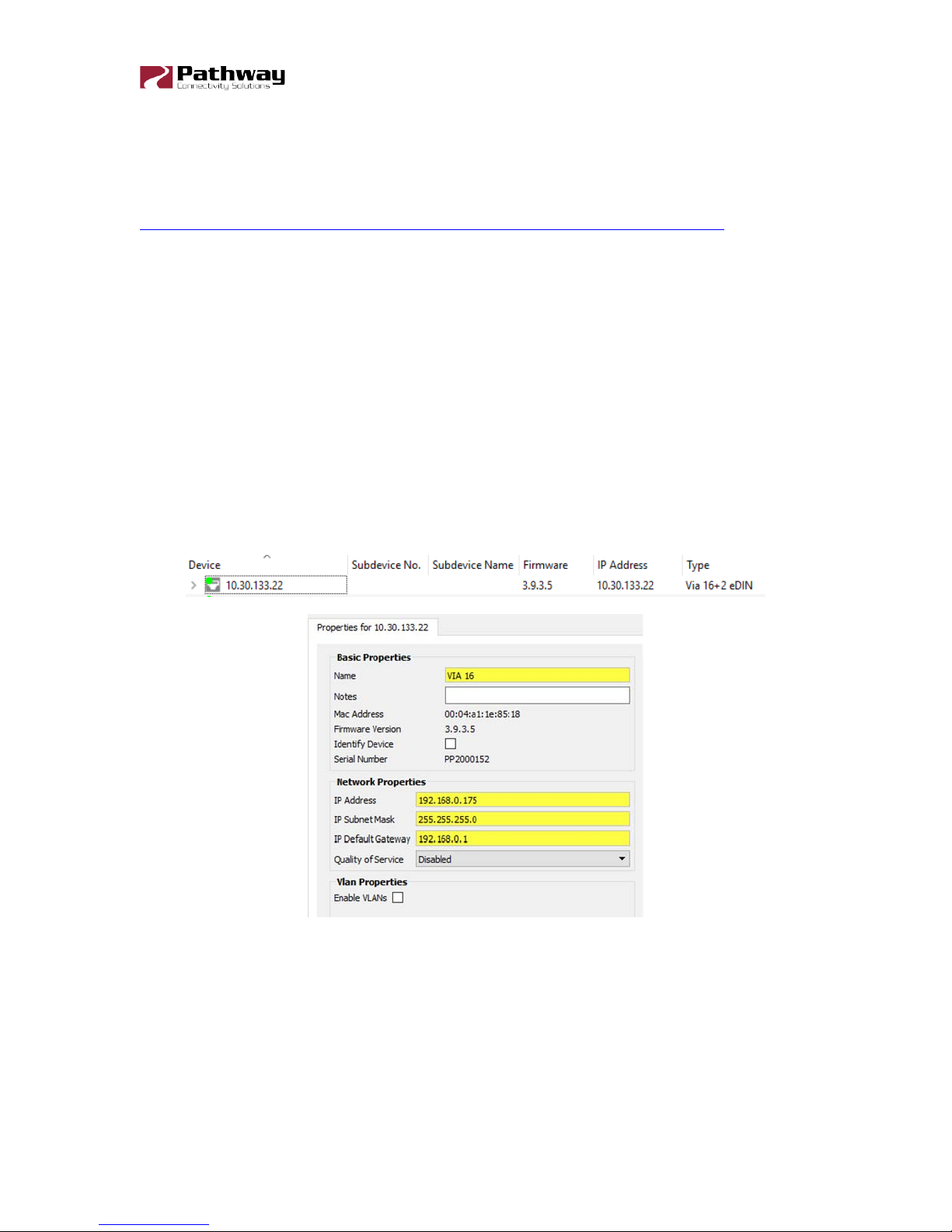
Network Setup
From the factory, the VIA16’s IP address is static, and set to 10.X.X.X (where X is between
0 and 254), with a subnet mask of 255.0.0.0 and a default gateway of 10.0.0.1. Before any
additional configuration, set the device’s IP address to the same subnet and IP range as the
computer and other devices on the lighting network.
Additionally, the VIA16’s name in the device list will be shown as its IP address. Give it a
useful name before continuing.
6716-200-REV1 2018-05-25 5
Page 6

6716 VIA16 Manual
Property
Description
Name
Name of the device. User-defined.
Notes
Additional notes. User-defined.
MAC Address
Factory-assigned media access control address. Read-only.
Current operating firmware version. Firmware may be updated
Firmware Update
This checkbox will show if the device is in Identify mode. You
Serial Number
Factory-assigned, Pathway serial number.
IP Address
Switch IP address.
IP Subnet Mask
Switch subnet mask.
IP Default Gateway
Switch default gateway.
Enable VLANs
Enable or disable VLANs.
Art-Net Alternate
Enable or disable Art-Net Alternate Mapping for Art-Net Trap &
Status of Ring Protect Mode.
Disabled
Master
Transit
Specifies the VLAN ID# used to determine the integrity of the
Device Properties
The following fields are shown in the device properties panel. Some are editable, while others
are read-only.
Firmware Version
Identify Device
Mapping
Ring Protect Mode
using the
can additionally turn Identify mode on or off using this checkbox
by clicking the box and then sending the transaction.
Convert feature
: Ring Protection feature is turned off
: Only one switch may be set as the Master.
button. Read-only.
: All other switches must be set as Transit.
Ring Protect Control
VLAN
Ring Protect Primary
Port
6716-200-REV1 2018-05-25 6
ring. May not be used for any other traffic. Valid ID# is any ID
outside the range set in VLAN setup. Default is VLAN 4095.
Designates which port to use as the active uplink port to other
switches. Valid range is port 15 thru 18.
Page 7

6716 VIA16 Manual
Ring Protect
Designates which port to use as the fall back link to other
Indicates the presence of an external power supply capable of
Enter the power rating of the external supply (in Watts). Default
User-defined ID number. If desired, enter a numerical
Secondary Port
switches. Valid range is port 15 thru 18.
RSTP Enable Enable / Disable the Rapid Spanning Tree Protocol (RSTP).
PoE External Supply
Present
PoE External Supply
Power (W)
User ID
supplying PoE (48VDC). Green PoE LED on VIA16 panel will also
indicate this (lit if present, off if not present).
value is 0. The PoE LED on the VIA16 panel will flash green as a
reminder if this value is left at 0.
identification number. Default is 0.
NOTE: The PoE External Supply Power must be entered or PoE will not function. All PoE
values will be reported as 0.0W.
6716-200-REV1 2018-05-25 7
Page 8

6716 VIA16 Manual
Property
Description
Disabled (default)
Enabled
Advanced Settings
VLAN Support
VLAN support must be enabled to allow access to the Ring Protect feature and to the VLAN
set up and configuration menus. Once Ring Protection is enabled, VLAN support cannot be
disabled. Click the checkbox in the Device Properties panel to enable VLANs.
Enable VLANs
feature
. Must be enabled to show VLAN Setup and Ring Protect
VLAN Setup
Plan your VLAN layout before attempting configuration. The creation of a map of the network,
showing which devices and which ports to associate with a given VLAN, is strongly
recommended prior to configuration.
EXTREMELY IMPORTANT NOTE: When configuring one or multiple VIA switches using
Pathway’s software-based configuration tools, be certain all switches are set to the
same Management VLAN ID#. Be certain that the port connected to your computer is
also on the same VLAN ID#, and is not on a tagged port. Failure to observe this rule
will result in what appears to be a broken network, and embarrassment upon realizing
the operator error.
Set the Management VLAN ID# in the Device Properties panel.
For more information on VLANs and definition of terms, see the appendix.
6716-200-REV1 2018-05-25 8
Page 9

6716 VIA16 Manual
Property
Description
Specifies lowest VLAN ID# available.
Specifies highest VLAN ID# available.
Specifies the VLAN ID# used by the management
VLAN Range Start: <x>
Valid range: 1 to 4095. Default is 1.
VLAN Range End: <x>
Valid range: 1 to 4095. Default is 10.
processor. Default is 1.
Management VLAN ID:<x>
This value MUST be within the range specified by the range
start and end set above, or you will not be able to configure
the switch.
These properties determine the size of the VLAN table, and which VLAN has communication
with the switch’s management processor. For efficient switch operation, the VLAN range
should be kept as small as necessary.
If the Management VLAN is accidentally set to a value outside the VLAN range, it may be
necessary to use the Factory Reset button, to restore communication with the management
processor and allow further configuration.
The VLAN range and individual VLAN configuration must be done prior to activating the Ring
Protect feature.
VLAN Configuration
Click on the VLAN Configuration tab. A list of VLAN IDs is shown.
Each VLAN is identified by its VLAN ID#. It is not currently possible to soft label VLANs.
Although you can name a VLAN for use in the VLAN patch, you cannot assign a port on the
network to use the VLAN soft label, only its numeric VLAN ID.
6716-200-REV1 2018-05-25 9
Page 10

6716 VIA16 Manual
Property
Description
Determines how IP settings will be obtained
Disabled (default):
Static
Dynamic
IP Address
Manually set IP address (IPv4).
Each VLAN ID# must be configured separately, and each VIA switch must be uniquely
identified on each VLAN in use on that switch. There is currently no way of copying properties
from one VLAN to another.
The VLAN ID# is assigned to individual ports in the VLAN Patch tab.
VLAN Configuration: Network Settings
IP Mode
: IP settings manually set by user.
: IP settings will be obtained from a DHCP server.
Subnet Mask Set subnet mask
Default Gateway Set default gateway
No IP assigned.
Network Settings must be configured on any VLAN requiring use of multicast filtering (IGMP)
or a DHCP server. By default, only the management VLAN (VLAN ID#1 by default) is
automatically assigned an IP and subnet mask. All other VLANs default to a null IP address
value (0.0.0.0). From the Network Settings for each VLAN, assign a unique IP per switch, a
common subnet mask and, where necessary, a default gateway.
Default gateway addresses are not typically required on most entertainment installations, as
these systems do not typically connect to the Internet. Any Internet access will be through a
proxy or NAT gateway, in which case the default gateway IP should point to this device.
IP Mode must be set to “Static” if the VIA is to act as a DHCP server. Only one DHCP server
may be active on any given VLAN. Setting the IP Mode to “Dynamic” does NOT enable the
DHCP server – see below.
If the IP Mode is set to “Dynamic” on a system with no active DHCP server, the switch will
auto-generate IP settings in accordance with zeroconf standards, in the IP range of
169.254.x.x/16. This range may not be suitable for connection to entertainment systems.
6716-200-REV1 2018-05-25 10
Page 11

6716 VIA16 Manual
Property
Description
Disabled (default): DHCP service is turned off. Use this
set) IP systems, and for all
switches other than the VLAN’s designated DHCP server
Enabled:
Set the first available IP address.
The DHCP pool is partially predefined based on the IP
address and subnet mask of the host switch, as the host
DHCP Server Range End
Set the last available IP address.
When in doubt, we recommend using a mode of ‘Static’ and configuring each switch and
VLAN combination with a unique IP address and appropriate subnet mask.
VLAN Configuration: DHCP Server
VIA switches can automatically assign IP addresses to connected devices, using a DHCP
(dynamic host configuration protocol) server.
Important: Only one DHCP server may be active on any given VLAN at one time. Running
multiple DHCP servers will cause network reliability problems.
The DHCP-hosting VIA switch must first be set to a static IP address on the desired VLAN,
prior to enabling the DHCP server. The DHCP server should be enabled prior to setting other
connected devices to a “Dynamic IP” mode or being connected to the network VLAN.
In some cases, it may be necessary to reboot connected devices to ensure the DHCP server
correctly recognizes them and assigns appropriate network settings.
setting for all static (manually-
DHCP Server Enable
host.
Enables DHCP server.
DHCP Server Range
Start
must have proper communication with the requesting device.
6716-200-REV1 2018-05-25 11
Page 12

6716 VIA16 Manual
Property
Explanation
Enable/disable IGMP snooping – allows the switch to
Enable/disable the IGMP querier – creates the multicast
VLAN Configuration: IGMP
When using multicast data packets, such as streaming ACN (sACN), bandwidth efficiency
may be improved by using IGMP (Internet group management protocol) to enable multicast
filtering.
IGMP Snooping
IGMP Querier
The IGMP Querier establishes a table of active multicast groups by querying connected
devices about which multicast groups each device wishes to join. For example, a gateway
will request the multicast groups associated with the sACN universes that the gateway is
patched to.
Each switch operating an IGMP Querier on a VLAN must have valid IP settings on that VLAN.
The IP settings may be static or dynamically established using the DHCP.
IMPORTANT: Two IGMP queriers should be active on each VLAN using multicast filtering. If
no querier is active, the groupings table will fail after approximately five minutes and filtering
will only work erratically or will fail altogether. IGMP should not be enabled on more than four
VLANs per switch.
The IGMP Snooper allows the switch to more efficiently route multicast traffic by applying the
multicast groupings as a filter. Multicast traffic is only directed to only those ports, i.e. end
devices, that have requested to receive that traffic.
correctly filter multi-cast traffic
tables used by snooping
Watch the following video on Pathway’s YouTube channel for a detailed explanation of IGMP
Snooping:
https://www.youtube.com/watch?v=0MVE22JCIt4
And the following video for a real-world example.
https://www.youtube.com/watch?v=CdXl_Q7KZC0
6716-200-REV1 2018-05-25 12
Page 13

6716 VIA16 Manual
Property
Description
Status of Ring Protect Mode.
Disabled (default)
Master
Transit
Specifies the VLAN ID# used to determine the integrity of the
ID outside the range set in VLAN setup. Default is VLAN
Designates which port to use as the active uplink port to
Ring Protect Secondary
Ring Protect Setup
For Ring Protect mode to function, VLAN support must be enabled.
: Ring Protection feature is turned off
Ring Protect Mode
: Only one switch may be set as the Master.
: All other switches must be set as Transit.
Ring Protect Control VLAN
ring. May not be used for any other traffic. Valid ID# is any
4095.
Ring Protect Primary Port
other switches. Valid range is port 15 thru 18.
Designates which port to use as the fall back link to other
Port
switches. Valid range is port 15 thru 18.
Warning: Ring Protection should only be configured and enabled after all other VLAN
configuration has been completed.
During the setup and configuration of the Ring Protection feature, communication between
devices may be erratic or broken. We strongly recommend that all switches be configured
with the appropriate Ring Protection settings PRIOR to be connected together. We also
strongly recommend that all switches be disconnected from one another PRIOR to disabling
the ring feature.
Prior to setup, determine which switch will be the master. Generally, the least busy switch in
a position with the most stable power (i.e., not on a roving platform) is the best choice. All
other switches must be configured as transit switches.
All switches must have both a primary and a secondary ring port set. These ports will be
automatically configured as Tagged (uplink) ports, meaning all traffic on all VLANs will be
passed through the ports. Tagged ports must be connected to other tagged ports on other
switches. Do not connect gateways or computers to tagged ports.
6716-200-REV1 2018-05-25 13
Page 14

6716 VIA16 Manual
Property
Description
RSTP Enable
Enable / Disable The Rapid Spanning Tree Protocol (RSTP).
If changes are made to the ring configuration while the ring is active, it may be necessary to
reboot all switches for the changes to take effect.
Rapid Spanning Tree
Warning: Rapid Spanning Tree must be enabled on all switches to detect loops correctly.
Network loops created through un-managed switches may not be detected correctly.
Pathway's implementation of Rapid Spanning Tree Protocol should be inter-operable with
other switch manufacturer's implementations.
The Rapid Spanning Tree algorithm detects and prevents network loops. The interaction
between RSTP and the Ring Protect system may cause long network re configuration times
when the ring topology is changed. For this reason, it is recommended that RSTP be used
during setup and then disabled after verifying there are no loops present.
For more information, please refer to the Appendix.
Art-Net Alternate Mapping
This feature is used in conjunction with the “Art-Net Trap-and-Convert to sACN”, feature. It
does not affect unicast Art-Net packets.
The Art-Net protocol uses two hexadecimal numbers, a ‘subnet’ and a ‘universe’, to define
its DMX universe numbering. Numbering is usually shown as # - # and the valid range is from
0 - 0 (zero-zero) to F- F.
However, most other common protocols, including sACN, do not have a universe ‘zero’. The
issue is compounded because some Art-Net implementations are shown in a straight
decimal representation (1, 2, 3, 4…) without any indication if “1” corresponds to Art-Net
universe 0-0 or to 0-1.
By default, Art-Net Universe 0-0 is ignored by the VIA and the packets discarded. When
Alternate Art-Net Mapping is enabled, VIA switches will map Art-Net Universe 0-0 to sACN
Universe 1. When Alternate Art-Net Mapping is disabled, Art-Net Universe 0-0 will be ignored
by the VIA and Art-Net Universe 0-1 will be routed as sACN Universe 1.
6716-200-REV1 2018-05-25 14
Page 15
6716 VIA16 Manual
Property
Description
Disabled (default): Disables QoS-based routing. All traffic is
Standard:
Dante Strict:
specified weighting. Lower priority traffic may be dropped or
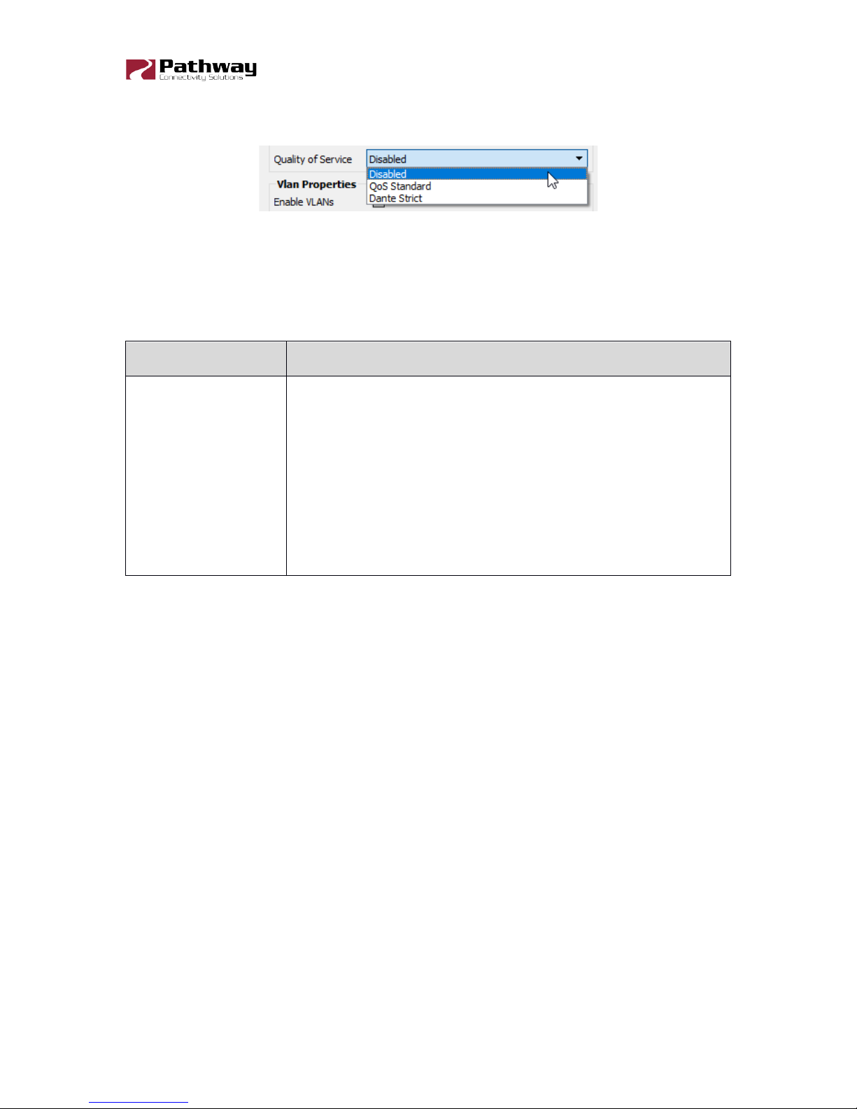
Quality of Service (QoS)
Quality of Service determines the relative priority of different data packets, which in turn
determines which packets should receive preferential routing from a VIA switch. QoS is often
used for the distribution of video and audio signals, including the Dante® audio standard, to
meet the signal’s required timing constraints. Please remember that giving all data high
priority is the same as treating all traffic equally.
treated equally.
Traffic priority is observed using a weighted algorithm
Quality of Service
to ensure timely delivery of high priority traffic and eventual delivery
of lower priority packets.
Traffic priority is strictly observed, using Dante-
ignored to ensure delivery of Dante’s high priority packets.
For more information, please refer to the Appendix.
6716-200-REV1 2018-05-25 15
Page 16

6716 VIA16 Manual
Factory Default
In the event of a loss of communication with the device (eg. Management VLAN accidentally
set to a value outside the VLAN range), it is possible to reset the switch to factory settings.
While powered, insert the tip of a pen or paperclip into the small hole in the front panel next
to the PoE LED and press and hold the reset button for 5 seconds.
The switch will then reboot with the default configuration from the factory.
6716-200-REV1 2018-05-25 16
Page 17

6716 VIA16 Manual
Property
Description
Name
Name of the port. Default is the port number. User-defined.
Notes
Additional notes. User-defined.
Disable: Disables the port.
Auto Negotiate (default, recommended):
10Mbit Half Duplex
10Mbit Full Duplex
100Mbit Half Duplex
100Mbit Full Duplex
1Gbit Full Duplex (Fiber Ports Only)
Port Properties and Configuration
Port Status and properties may be reviewed by expanding the device in the device tree, and
clicking on a subdevice, or port. The properties for that port will then be shown in the
properties panel.
The following fields are shown in the subdevice/port properties panel. Some are editable,
while others are read-only.
Link Mode
Allows the switch
and the connected device to determine the fastest mutually
supported connection speed. Read-only.
6716-200-REV1 2018-05-25 17
Page 18

6716 VIA16 Manual
Shows the status of the link (up or down) and the link speed.
Shows the type of port currently selected (Copper RJ45 or
If the connected device supports Link Layer Discovery Protocol
Traffic forwarding state of the port: Forwarding all traffic or
Shows the bandwidth used on the selected port. Bandwidth is
i.e. if the port is set to 100Mbit, a bandwidth use of 55% is
Untagged (normal, default): Only data belonging to the port’s
specified VLAN ID# will be transmitted. Typically set when
Tagged (Uplink): All traffic on all VLANs will be transmitted.
Assigns the selected port to a specified VLAN. Performs the
When enabled, Art-Net data packets with broadcast address
destinations are trapped and converted to E1.31 sACN
The resulting sACN packets may then be filtered using the
Enabled by default, this option allows the user to completely
Link Status
Port Type
LLDP Partner
Forwarding State
Bandwidth Percentage
Tagged/Uplink
Read-only.
Gigabit Capable Fiber). Read-only.
(LLDP), such as Pathway Pathport gateways and VIA switches,
the connected device’s name will appear here. Read-only.
Blocked by RSTP detecting a loop. RSTP must be active.
Read-only.
relative to the port speed as negotiated with the link partner,
equal to approximately 55Mbit of traffic per second. Read-only.
connected to end equipment.
Typically set when connected to another switch.
Port VLAN ID
same function as double-clicking a VLAN in the VLAN Patch
tab.
Art-Net Trap and
Convert Enable
multicast packets, as the packets enter the port of the switch.
IGMP settings.
disable PoE on a given port, which may be useful for rebooting
Port PoE
end devices like gateways without having to go to the switch
and unplug cables. Any PoE allocation set with the following
parameter will be ignored. Ports 1-12 only.
6716-200-REV1 2018-05-25 18
Page 19

6716 VIA16 Manual
The PoE class as reported by device. Read-only.
Not Detected
Class 0:
Class 1:
Class 2:
Class 3:
PoE Active Draw (mW)
PoE Power Allocation
Sets the PoE allocation for the port. Default is 15.4W,
Allocation options range from 0.9W to 15.4W, in 900mW
: not a PoE device
PoE Status
(mW)
PoE Max Allocation
No class reported, 15.4W draw assumed
Uses up to 4W
Uses up to 7W
Uses up to 15.4W
Consumption as reported by the PoE controller, in milliwatts.
Reports the maximum draw, in milliwatts, allowed by the PoE
class, or the limit set by the user, whichever is less.
regardless of the size of the power supply.
increments.
6716-200-REV1 2018-05-25 19
Page 20

6716 VIA16 Manual
Property
Description
Untagged (normal, default): Only data belonging to the port’s
specified VLAN ID# will be transmitted. Typically set when
Tagged (Uplink):
VLAN Type
VLANs must be enabled from the Advanced Settings menu for this option to be shown.
VLAN
Once VLANs are enabled and the VLAN range is set, by default a port is set as Untagged
(Normal) with a VLAN ID# of 1, or the lowest ID# of the VLAN range.
Ports set as Untagged only transmit data packets in the VLAN specified by the ID# and are
typically connected to end equipment.
Ports set as Tagged do not require a VLAN ID#, and this option will not be shown. Tagged
ports transmit all data packets regardless of the packet’s VLAN ID. Tagged ports should only
be connected to other tagged ports, typically on other switches. Do not connect Pathport
gateways or other devices like computers unless you have specifically configured your
Ethernet port to receive tagged data (advanced network setup only).
Generally, a Tagged port on one switch should not be connected to an Untagged port on
another switch.
connected to end equipment.
All traffic on all VLANs will be transmitted.
6716-200-REV1 2018-05-25 20
Page 21

6716 VIA16 Manual
Property
Description
Sets the VLAN tag used by the port. Only data packets
VLAN ID#
The VLAN ID# option is only shown for ports set as Untagged.
belonging to this VLAN ID will be transmitted by the port.
In Pathscape’s VLAN Configuration tab, if you expand a VLAN
VLAN ID#
and highlight one of the switches using that VLAN, one of the
Properties is the VLAN NAME. This can be set to something
appropriate like “Lighting” or “Audio”. Note that the VLAN ID is
network wide and the VLAN NAME is associated per switch.
The name will appear on the switch’s front panel display when
setting Ports to VLANs.
Currently it is not possible to set a soft label for VLAN ID#.
6716-200-REV1 2018-05-25 21
Page 22

6716 VIA16 Manual
Art-Net Trap-and-Convert
When enabled, Art-Net data packets with broadcast address destinations are trapped and
converted to E1.31 sACN multicast packets, as the packets enter the port of the switch. The
resulting sACN packets may then be filtered using the IGMP settings. All other Art-Net
broadcast packets, such as ArtPoll, are discarded. Depending on the amount of Art-Net data
traffic, this operation could significantly improve bandwidth usage efficiency and reduce the
amount of unnecessary traffic seen by end devices.
The Art-Net packet will be converted to the analogous sACN universe. Due to how Art-Net
universes are numbered, there is the possibility of an off-by-one error. Change the “Art-Net
Alternate Mapping” option should the universe mapping seem incorrect.
Although performance depends on DMX frame rate, conversion of no more than 48 Art-Net
universes by one VIA at one time is recommended.
Currently, there is no method of converting the sACN back to Art-Net. This feature assumes
the DMX gateways can receive sACN instead of Art-Net.
When this feature is disabled, Art-Net data will be routed as normal broadcast traffic to all
devices on the current VLAN.
Port Enable/Disable
Enabled by default, this option allows the user to completely disable PoE on a given port.
Any PoE allocation set with the following parameter will be ignored.
6716-200-REV1 2018-05-25 22
Page 23

6716 VIA16 Manual
Port PoE Setup/Status
Allows review and management of power consumption used by devices running on Powerover-Ethernet (PoE).
Except for Maximum Allocation, the PoE settings are not user-editable. The Maximum PoE
Allocation allows you to set an upper limit to the power available to a connected device, such
as a Pathport gateway of Vignette wall station. Use Maximum Allocation to ensure critical
devices will have power. Also use Maximum Allocation to compensate for Class 0 device
power allocation. Many older PoE devices cannot report their class. The switch automatically
treats these devices as Class 0 and allocates the full, default 15.4W to their ports.
If Maximum Allocation for every port is left at 15.4W, PoE is allocated by the switch: a) when
the switch is powered up, PoE is allocated starting with Port 1, then port-by-port through
port 12; or b) PoE is allocated on a first-come, first-serve basis, dependent on the order
devices are plugged into the switch.
Troubleshooting tip: If the green PoE LED on the front panel is blinking, the maximum
allocation is too low for the connected device, the PoE power supply has not been set up
(see note below) or all available power is already allocated.
IMPORTANT NOTE: The VIA16 ships with hardware support for IEEE 802.3af Power-overEthernet standard (PoE). To make use of this hardware, an external 48VDC auxiliary power
supply, such as Pathway P/N 1001-100-48-DIN, must be connected to the VIA12.
Once the power supply is connected, the VIA must be configured with the size – in watts –
of the PoE supply.
LLDP Link Partner
Link Layer Discovery Protocol (LLDP) is an industry-standard method for device
announcement and reporting described in the IEEE 802.1AB standard. Any Ethernet-aware
device may announce itself using LLDP, not just switches.
For Pathway devices supporting LLDP, the name shown in the LLDP Partner field will be the
device’s name, as configured in Pathscape. Other LLDP-enabled devices may return
6716-200-REV1 2018-05-25 23
Page 24

6716 VIA16 Manual
different information. This property is only shown when a device is connected to the port in
question.
Port Link Mode
Allows review and editing of the port’s communication speed.
Auto-negotiation allows the switch and the connected device to determine the fastest
mutually supported connection speed. However, there are some situations where, due to
poor cabling, interference or traffic congestion, ability to force the connection to a particular
speed is desirable.
Range is from 10Mb – Half Duplex (a common value for older gateways) to 100Mb – Full
Duplex. The port may also be disabled.
NOTE: It is not possible to force a device to connect at a speed faster than the device’s
network interface hardware will support.
For fiber ports, the Link Mode has only two options: Enable or Disable the port.
Forwarding State
Shows the forwarding state for the selected Port. Typically, this will show “Forwarding all
traffic”. If RSTP is enabled and a network loop is detected, RSTP will block the port that is
creating the loop. In this case, the Forwarding State will be shown as “Blocked by RSTP”.
Bandwidth Percentage
Shows, as a percentage value, the bandwidth used on the selected port. Bandwidth is
relative to the port speed as negotiated with the link partner, i.e. if the port is set to 100Mbit,
a bandwidth use of 55% is equal to approximately 55Mbit of traffic per second.
6716-200-REV1 2018-05-25 24
Page 25

6716 VIA16 Manual
Property
Description
Not Detected
No module inserted
Not Support
Module is not compatible/supported
1000Base-SX
Module is recognized as type noted
1000Base-LX
Module is recognized as type noted
SFP Module (Fiber Ports Only)
6716-200-REV1 2018-05-25 25
Page 26
6716 VIA16 Manual
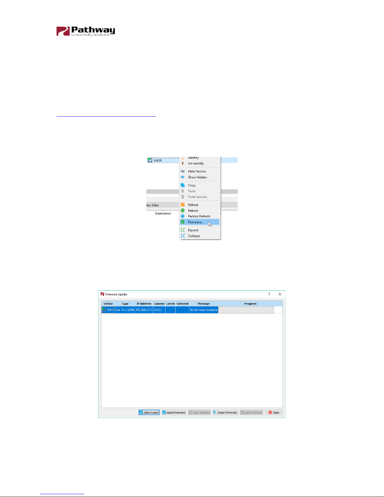
Firmware Upgrades
Firmware upgrades may only be done using Pathscape.
The most recently released firmware is bundled with the most recent version of Pathscape.
To ensure you have the most up-to-date firmware available for upgrading, ensure you have
downloaded the most recent version of Pathscape from the Pathway site,
http://www.pathwayconnect.com
To upgrade a VIA switch, ensure the device’s IP address is configured correctly and is on
the same subnet and IP range as the computer. Open Pathscape and select the device in
the Device list. Right-click the device and choose
.
Firmware…
This will bring up the Firmware Update window. Select the VIA16, and click the Select Latest
button at the bottom of the window. The latest firmware version will be shown in the table
next to “Current”. Click the
After the device reboots, the firmware is updated.
Send Firmware button, and wait for the progress bar to finish.
If the current firmware is already the most recent, clicking the Select Latest will do nothing,
and the message “No Firmware Available” will be shown.
6716-200-REV1 2018-05-25 26
Page 27

6716 VIA16 Manual
Appendix 1: SFP Fiber Adapter Selection
The VIA16 allows the end user to provide a fiber adaptor. The adaptors are typically referred
to as an SFP (Small Form Pluggable transceiver) or mini-GBIC (gigabit interface converter).
Pathway part number 6799 is an SFP 850nm Ethernet Optical Transceiver that is compatible
with VIA10, VIA12 and VIA16. The dual-mode fiber is also compatible with the 6706 VIA5 +
Fiber. These fiber links can go up to 550 m (1800 feet) without issue. In some situations, the
run lengths may lead you to choose a different SFP. Follow these guidelines when choosing
your SFP:
1. The form factor must be stated as SFP (not SFP+, XENpack or others).
2. The fiber connector is LC Duplex.
3. The SFP must support Optical Gigabit Ethernet (typically referred to as 1000BASE-
SX or 1000BASE-LX)
4. The SFP must match the type of fiber installed, either Single Mode or Multi-Mode.
5. The SFP must support the distance required, which in turn determines the optical
wavelength. 850nm is typically used for runs up to 550m, while 1310nm is typically
used for runs up to 10km.
We strongly recommend each end of the connection use an identical SFP.
When the SFP module is inserted in the switch, the corresponding Link/Activity LED will light
up green. If an incompatible module is detected, the LED will light up red. In Pathscape, the
Subdevice properties panel will indicate the link status, SFP Module Type (1000BASE-LX or
1000BASE-SX), as well as the LLDP Partner.
NOTE: The VIA16 will only work with 1000BASE-SX or 1000BASE-LX fiber modules.
When connecting a VIA to another manufacturer’s switch using fiber, please bear in mind
that some switches check the manufacturer’s ID, as announced by the SFP module, and will
only connect to a matching brand. VIA switches do not perform a manufacturer’s ID check,
and should work with any SFP module meeting the criteria above (Cisco, Finisar, Netgear,
etc.)
6716-200-REV1 2018-05-25 27
Page 28

6716 VIA16 Manual
Appendix 2: Virtual Local Area Network (VLAN)
A VLAN (Virtual Local Area Network) is a group of ports on the switch (or switches) that are
configured to pass traffic to one another, but not to ports on any other VLAN. When multiple
VLANs are established, some ports on the switch may need to be configured specifically to
pass all VLAN traffic, to ensure overall traffic is routed correctly.
This feature allows the user to arrange lighting consoles, gateways and other network gear
into groups of equipment. The usual purpose is to minimize unnecessary traffic to the
equipment, or to segregate different types of equipment (lighting, audio, video) so that the
network does not get flooded with redundant data.
Definitions
VLAN naming practices can be confusing. The following terms are paired interchangeably in
this manual: Normal and Untagged; Uplink and Tagged.
Normal/Untagged ports belong to a specific VLAN as configured by the user, and will only
pass traffic that belongs to that VLAN. Typically connected to end equipment.
Uplink/Tagged ports pass all network traffic with VLAN ‘tags’ within the VLAN range
established for that switch (see Range Configuration below). Typically connected to other
switches.
Tag refers to the marker added to (or removed from) the data packet as the packet enters
or exits from a Normal/Untagged port on the switch. The “Tag” determines which VLAN the
data packet is assigned to.
Management VLAN refers to the VLAN that the switch’s management processor is assigned
to use. Care must be taken that the Management VLAN is used by at least one
Normal/Untagged port on the switch, or the ability to configure the switch may be lost. It is
strongly recommended that the Management VLAN be identical to the VLAN Range Start.
VLAN ID (ID#) is assigned to Normal/Untagged ports and determines which VLAN that port
operates within.
A Normal/Untagged port may only be associated with one VLAN ID# at a given time.
6716-200-REV1 2018-05-25 28
Page 29

6716 VIA16 Manual
Software Configuration of VLANs
VLANs may be configured with Pathscape. Refer to software documentation for complete
configuration instructions.
When configuring the switch, make sure your computer is connected to a Normal (Untagged)
port set to the same VLAN ID# as used by the management processor. Failure to do so will
prevent configuration from being applied.
VLAN Guidelines
Plan the VLAN layout first. The creation of a map of the network, showing which devices to
associate with which VLAN, is strongly recommended prior to configuration.
In general, ports connected to end devices will be configured as Normal/Untagged and given
a VLAN ID#.
Ports connected to other VIA switches will typically be set as Uplink/Tagged, so multiple
VLANs may be forwarded between switches, or when a VLAN must be forwarded through
an intermediate switch (where that VLAN is not in use) on to a third switch beyond. It is
possible to set the ports to Normal/Untagged, and given a VLAN ID#, in cases where it’s
desirable to pass only one VLAN between switches, but this is not a normal practice.
It is strongly recommended that the ports used to connect separate VIA switches should be
set to matching configurations.
When configuring VLANs, remember that each switch must be uniquely identified on each
VLAN in use on that switch. By default, only the management VLAN is automatically assigned
an IP and subnet mask. All other VLANs default to a null IP address value (0.0.0.0). Use the
network configuration options available from the VLAN Configuration tab to configure the
desired IP settings for each VLAN.
6716-200-REV1 2018-05-25 29
Page 30

VLAN ID#
1 2 3 4 5 6 7
8
Label
IP Address
Subnet Mask
Default Gateway
IGMP Snooping
IGMP Querier
DHCP Server
Art-Net Alternate
Mapping
QoS Level
Page 31

6716 VIA16 Manual
6716-200-REV1 2018-05-25 31
Switch Label:
Port 1 2 3 4 5 6 7 8 9 10
11
12
13
14
15
16
17
18
Connected
Device
Normal/Uplink
VLAN ID#
ArtNet to sACN
PoE Max
Link Mode
SFP Type
Page 32

Appendix 3: Ring Protection
Ethernet wiring schemes are based on a ‘star’-wiring topology. Ring (or loop) data wiring –
where the last device in a chain is wired back to the first device – is forbidden. Only one data
path between any two devices is allowed.
But star-wiring layouts are prone to single point failures. Unlike DMX512 transmission,
passive data ‘thru’ connections are not possible with Ethernet, which means there is no
redundancy under normal operation. A severed cable or power loss to a switch can mean
the loss of some or even all show control.
Ring Protection allows the deliberate – and designed – use of a ring wiring system for
Ethernet communications. When in this mode, VIA switches ignore data traffic on one
segment of the ring, while monitoring the integrity of the remaining connections. If an
interruption is detected, the unused ring segment is activated and full communication is
restored. Fail-over time is between 50 and 75 milliseconds, or two to four DMX packets.
Requirements and Limitations
VLANs must be enabled to use Ring Protection. The mode uses a dedicated VLAN to monitor
the integrity of the ring, called a
VLAN. By default, VLAN 4095 is used. This does not mean your VLAN range needs to extend
to 4095. Typically an entertainment network may use 1-3 or 1-10 VLANs.
Control VLAN. All switches must use the same Control
Only ports 15 thru 18 may be used with this feature.
Ring Protection works with Pathway VIA switches only. Switches from other manufacturers
can co-exist on the network, but should not be placed in-line with the ring.
Definitions
Master switch monitors the integrity of communications. Only one switch on the network
may be configured as the master. If choice is available, the least busy switch, with the most
reliable power source, preferably on an uninterruptible power supply, should be chosen as
the master.
Transit switches receive and forward the ring monitoring packets. All switches other than the
Master must be set as transit switches.
Note: Ring Protection wiring topology is not structured. No care need be taken when
connecting primary and secondary ports together – any arrangement is acceptable.
Page 33

6716 VIA16 Manual
Primary port is the main (active) UPLINK connection link on the Master switch, joining to the
rest of the network. All transit switches must also have one port configured as the primary.
Only ports 15 through 18 are available to be used as the primary port. If using copper,
typically port 15 will be primary and 16 will be secondary. If using fiber, port 17 is primary
and port 18 is secondary.
Secondary port is an UPLINK port ‘ignored’ (logically blocked) by the Master switch to break
the ring topology. All transit switches also must have one port configured as the secondary
port. The secondary port is actively used on transit switches. Only ports 15 through 18 are
available to be used as the secondary port.
Appendix 4: Rapid Spanning Tree Protocol
The Rapid Spanning Tree Protocol (RSTP) is another technology to prevent network loops.
EAPS requires more setup, as it needs a dedicated master and multiple transit switches, but
this allows it to function within a few DMX frames during fail-over. RSTP only requires you to
turn on the feature on all the switches in the network. No further dedicated port configuration
or special wiring considerations need to be adhered to.
6716-200-REV1 2018-05-25 33
Page 34

6716 VIA16 Manual
QoS Setting
Description
Disabled (default)
Disables QoS-based routing. All traffic is treated equally.
Queue 1: DSCP values 1-16
Queue 1: All DSCP values except:
Appendix 5: QoS Settings
Quality of Service priorities are determined by the Differentiated Services Code Point (DSCP)
field contained in each data packet header. DSCP values may range from 1 to 64, and are
mapped to four egress (output) queues. The egress queues are, in turn, numbered from 1
(Best Effort) to 4 (Highest Priority).
The DSCP mappings and related QoS settings used by VIA switches is shown in the following
table:
Queue 2: DSCP values 17-32
QoS Standard
Dante Strict
Queue 3: DSCP values 33-48
Queue 4: DSCP values 49-64
A weighted fair queuing algorithm is used to prevent the starvation
of lower queues by higher priority traffic.
Queue 2: DSCP 8
Queue 3: DSCP 46
Queue 4: DSCP 56
Queues 3 and 4 are handled by strict priority, while the two lower
queues are handled by the weighted algorithm.
6716-200-REV1 2018-05-25 34
 Loading...