

Page 1
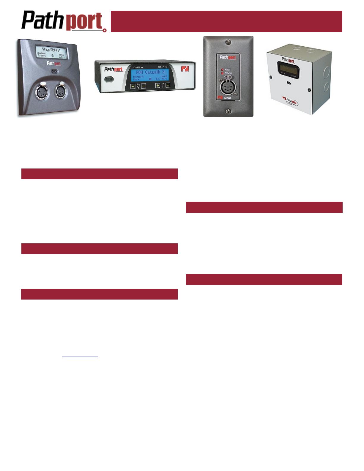
Installer’s Guide
This installation guide describes the requirements
for and the steps involved in the permanent
installation of Pathway C-series, D-series and Rseries two-port Pathport® nodes, and Uno single-port
nodes. Some familiarity with DMX512 and Ethernet
lighting networks is assumed.
PRE-CONFIGURATION
Pathport nodes hold their IP and patch configuration in
non-volatile memory. Significant on-site time savings can
be attained by configuring the node name and network
information in the shop. To do so, use the network requirements below to create a mock-up installation. Configure the nodes using Pathport Manager software. Put
temporary labels on the nodes showing their fit-up location, then repackage them for shipping.
ON-SITE CONFIGURATION
If nodes are not pre-configured, configuration can done
after installation, on-site. The configuration process will
involve recording the IP address of each node, and then
using Pathport Manager software.
NETWORK REQUIREMENTS - WIRING & LAYOUT
All network wiring should follow standard Ethernet wiring rules and be installed by a qualified person. Category
5 wiring or better is required. Pathway recommends following the Entertainment Services and Technology Association (ESTA) publication Recommended Practice for
Ethernet Cabling Systems in Entertainment Lighting Applications and its supplement. Both documents are avail-
able on-line at www.esta.org.
As part of the installation, all Ethernet wiring should be
certified under the TIA/EIA-568 standard. Pathway may
limit the technical support provided to nodes installed on
non-certified systems.
Good wiring practice does not allow terminating building
wire with a male RJ45 plug or the hard-wiring of data lines
to end devices. To facilitate proper practice, Pathport 2port nodes ship with an in-line female RJ45 mini-jack,
similar to a punchdown connector, as well as a short
male-to-male RJ45 jumper to connect the jack to the
node. The in-line jack can be installed by finger-pressure
alone, although pliers are recommended. A crimping tool
is not needed. The jumper and jack are available as an
accessory package for the Pathport Uno.
To install the in-line connector, first determine if the installation is using TIA568A or TIA568B wiring scheme.
Strip back the outer insulation jacket no more than ¾”.
Untwist the pairs, trim them to the same length but do not
remove insulation from the individual wire. Following the
applicable color coding scheme on the sticker, slip the
individual wires into the clear plastic guide piece. Position
the guide piece onto the connector half of the jack, and
press down or gently apply pressure with a pair of pliers
until the two pieces click together. The mini-inline connector is removable, if necessary.
NETWORK REQUIREMENTS - POE
Pathport nodes are designed to take advantage of the
IEEE 802.3af standard, commonly called Power-overEthernet (PoE). PoE-enabled switches are readily available, and their use is strongly recommended to simplify
installation and prevent the need for separate power cabling. Please note that the Pathport Uno can only by
powered using PoE and cannot be hooked up to an auxiliary supply.
NETWORK REQUIREMENTS - ETHERNET SWITCHES
For entertainment lighting networks, unmanaged or
plug-and-play switches are preferable to managed or enterprise switches. However with larger networks, sometimes the only switches available with the number of ports
required will be managed. There are two issues commonly encountered with managed switches. First is
broadcast storm control.
DMX-over-Ethernet protocols are multi-cast or broadcast protocols where one source (the console) sends all
the information to all the nodes and each node determines what part of the data stream to use. However the
management features of most switches are intended for
the unicast or one-to-one environment of an office. A
continual broadcast transmission looks like an error – a
broadcast storm – which the switch will try to block. In a
show situation, this would be disastrous. Broadcast storm
features must be disabled.
The other issue is multi-cast filtering. Managed
switches attempt to direct traffic in an intelligent manner
by learning what devices are on what port. Although useful in the unicast environment of an office, this feature can
bog down the lighting network and lead to lost packets.
The ‘snooping’ done to facilitate multi-cast filtering is
known to cause issues with broadcast protocols and so
Page 2
this feature, often called Inter Group Management Protocol (IGMP) should be turned off.
Other security features of the managed switch should
be examined. Most will not be necessary on a lighting
network and should be disabled. At the very least, this
will help keep the through-put speeds of the switch as
high as possible.
One feature that managed switches can provide that
unmanaged switches cannot is redundancy. Managed
switches can be configured to work around a problem or
even to activate a redundant leg of the network. In some
applications, this feature may be sufficiently desirable to
offset the added configuration time and expense.
For unmanaged and plug-and-play switches, the feature
sheets must be carefully examined to ensure broadcast
storm and IGMP filtering are not permanently turned on.
Switches should be connected to an uninterruptible
power supply (UPS) with power conditioning. A UPS allows for orderly shutdown in case of power failure, and
protects against spikes and brown-outs, which can cause
memory corruption or physical damage to the nodes.
OPERATING ENVIRONMENT
All Pathport nodes are designed for indoor use in a dry
location. To maximize equipment life and minimize unreliability and sudden failure, the following environment
should be maintained:
• ambient temperature extremes: -10 to +50 degrees C
• operating temperature: 0 to +40 degrees C
• relative humidity: 10 – 95%, non-condensing
• general conditions: clean, dust-free
Installer’s Guide
connector, use the male-to-male jumper (included) to connect it to the node. Otherwise, plug the male RJ45 pigtail
directly into the connector on the back of the node. Attach the green ground wire to the ground screw in the
backbox.
If local power is required for the node, see the note on
local power at the end of this guide.
Gently insert the node straight into the backbox, lifting it
slightly so that is high in the backbox. Once all the way in,
lower it slightly until the tabs at the top of the trim ring
take hold of the face plate. Once the top of the node’s
faceplate is retained, swing the bottom in tight to the wall.
Make sure no wiring or connectors are pinched or excessively bent or stressed. Using a #0 Phillips driver (not
included), tighten the two setscrews provided, one on
each side of the node’s face, to complete installation. If
the nodes have shipped with hex-head set screws, instead use a 1/16” Allen key (not provided)
The node is ready to be powered up.
C-SERIES NODE INSTALLATION
Disconnect all power before proceeding with the instal-
lation.
C-series nodes are designed to be installed in recessed, standard two-gang masonry deep backboxes
(ears in) for flush-mounting or, for surface mounting, in
Pathport surface mount backboxes, part number 6901.
Use of other surface mount backboxes is not recommended.
If the node has been pre-configured, check the temporary label to ensure the node is being installed in the correct location.
Check the installed backbox for obstructions or any foreign material. The backbox should be clean and empty.
Make sure there is a RJ45 female punchdown connector
in the box (preferred) or a male RJ45 pigtail. Install the
in-line jack provided, if necessary.
Attach the Pathport trim ring to the backbox with the 4
screws provided. Do not over-tighten or do anything that
will distort the shape of the trim ring.
Inspect the node and make sure all components are
secure and that the printed circuit boards are secure.
Note that it is normal to see exposed metal on the mating
connectors.
If the backbox contains an RJ45 female punchdown
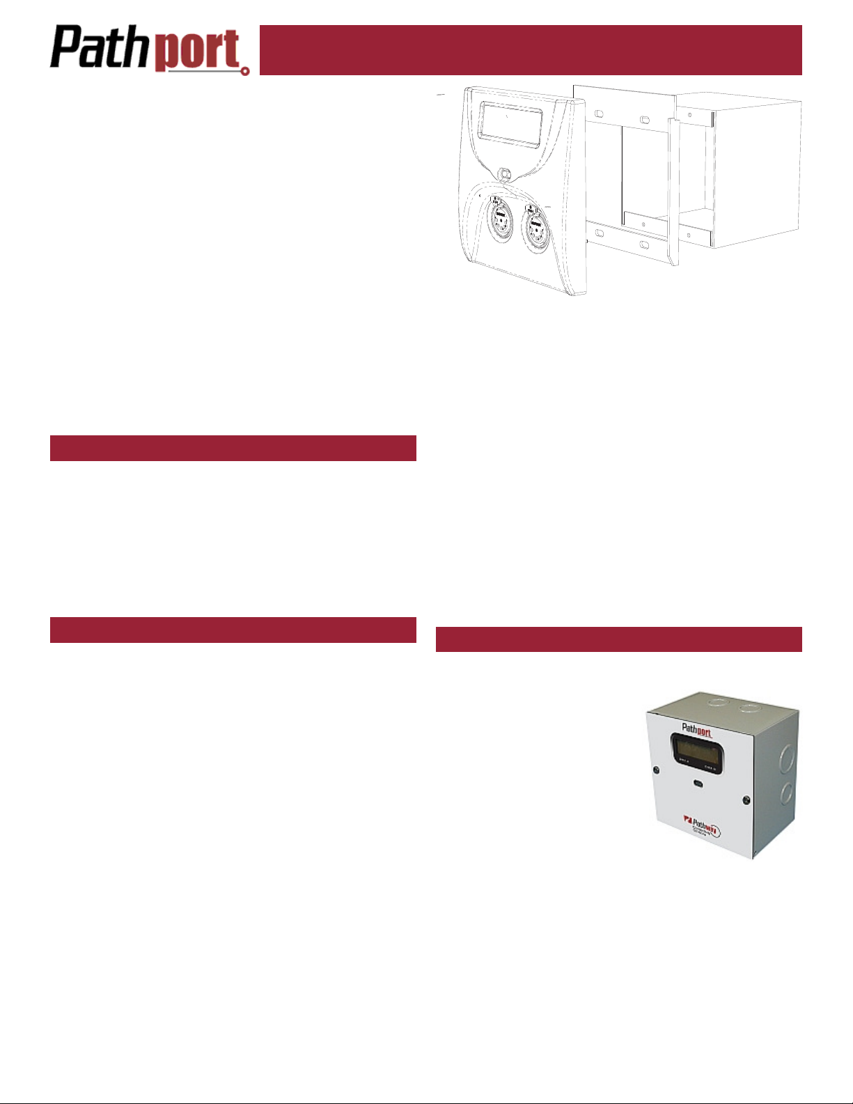
D-SERIES NODE INSTALLATION
Disconnect all power before proceeding with installa-
tion.
D-series nodes are surfacemount enclosures designed for
conduit-enclosed cabling connection to permanently installed
equipment such as dimmers
and relay cabinets. D-series
nodes are shipped attached to
their backboxes.
First, remove the two screws
holding the faceplate to the
backbox. Keep the screws for
later use. Gently remove the faceplate and attached
printed circuit boards. Put the faceplate in a safe and
clean location, such as back into its shipping container.
Determine the location of the backbox in relation to the
incoming and outgoing conduit lines. Remove the appropriate knockouts then securely mount the backbox to the
wall using appropriate fasteners. If the backbox must be
installed prior to the completion of the conduit and wiring
runs, then label the backbox and the container holding the
removed faceplate and store the container in a safe location. Make sure the two faceplate screws are stored in
2
Page 3

Installer’s Guide
the same box.
Attach the conduit runs to the enclosure using standard
connectors (not supplied). The backbox should be clean
and free of obstructions or foreign materials. Inside, there
should be one Cat5 wire with a female RJ45 punchdown
connector (if necessary, install the mini-jack included) and
one or two cables for the DMX connections, ending in
bare wires. Identify which cable is for DMX Universe A
and which is for DMX Universe B.
Retrieve the faceplate from the storage container. Inspect it for damage and to ensure the printed circuit
boards are securely fastened.
Using the XLR pin-out chart at the end of this guide,
attach the cable for DMX Universe A to the terminal block
marked DMX Port A. Repeat, if necessary, for DMX Port
B. If Cat5 cable is being used to complete the DMX run,
use the Cat5 pin-out guide instead.
Using the male-to-male jumper, connect the female
RJ45 connector to the connector on the back of the circuit
board of the node. If the Ethernet wiring has been terminated with a male RJ45 connector (not recommended),
plug it directly into the circuit board connector.
If local power is required, see the note at end of this
guide.
Gently position the faceplate on the backbox until the
screw holes line up, while taking care that no wiring is
pinched or excessively bent or stressed inside the box.
Using the original two screws, reattach the faceplate. Do
not over tighten.
The node is ready to be powered up.
R-SERIES INSTALLATION
Disconnect all
power before
proceeding with
installation.
R-series nodes are designed for installation in
standard EIA 19” racks, at least 18” deep. Up to two Rseries nodes may be installed in one RU of space, using
the included rack-mount ears. Nodes may be mounted
with the display or the connectors toward the front of the
rack. The side walls of the node have an identical screw
pattern at the front and rear. Rack ears can be mounted
on either side of the node.
Determine which direction the node is to face and remove the appropriate four 4-40 Phillips screws from each
side of the enclosure. Attach the 3 inch rack ear to one
side of the node with the pan-head screws included, reusing the 4-40 screw holes. If only one node is being
mounted in the rack space, attach the 10 inch rack ear to
the opposite side of the node, again using the pan-head
screws included. Attach the assembled unit to the rack
using standard rack screws (not included).
If two nodes are to be mounted side-by-side in the rack
space, attach the 3 inch ear to the opposite side of the
second node, again using the pan-head screws provided
into the empty 4-40 screw holes. Then attach the 1-inch
link-ears to the sides of the nodes facing each other using
the pan-head screws provided. Attach the two 1-inch linkears together using four of the Phillips 4-40 screws removed earlier. Do not tighten down completely. Attach
the assembled unit into the rack using standard rack
screws. Now tighten the 4-40 screws to finish the link-ear
assembly.
Plug in the appropriate XLR connectors to the node to
complete the DMX lines. If the node has terminal blocks,
use the XLR pin-out chart at the end of this guide. Attach
the cable for DMX Universe A to the terminal block
marked DMX Port A. Repeat for DMX Port B. If Cat5 cable is being used to complete the DMX run, use the Cat5
pin-out chart instead.
For most installations, the Ethernet switch is located in
the same rack as the nodes. Using a male-to-male RJ45
patch cable (not included), connect the female RJ45 jack
on the node to the switch. If the switch is located elsewhere, consult the appropriate drawings for the Ethernet
jack location.
The node is ready to be powered up. If auxiliary power
is required, see the note on local power at the end of this
guide.
PATHPORT UNO INSTALLATION
Disconnect all power before proceeding with installation. Pathport Unos can only be powered using Powerover-Ethernet.
Pathport Uno single-port nodes are
designed to be installed in recessed,
standard masonry deep backboxes
(ears in) for flush mounting, or deep
(minimum 58mm or 2.25”) surface
mount backboxes. Unos may also be
installed in multi-gang backboxes with
other low voltage devices or Pathway
modular receptacles. In this instance,
the single gang faceplate provided will
need to be replaced with a multi-gang
faceplate. Cover plates ranging from
double-gang up to 6-way, in brushed
stainless steel or black, are available from Pathway.
If the node has been pre-configured, check the temporary label to ensure the node is being installed in the correct location.
Two important things must be done prior to installing
the Uno. Uno nodes can be permanently set to a specific
DMX universe, 1 through 4, by use of a jumper on the
back edge of the circuit board. If the system designer has
not given specific instructions about the setting, then
leave the jumper in the NET position. This position will
allow the universe the node operates on to be set remotely at a later time.
Second, each Uno node ships with additional serial
number stickers. Do not lose these stickers. Because
Unos do not have a faceplate screen, serial numbers and
their locations are necessary to configure the system.
Losing track of this information will add considerable time
to commissioning.
3
Page 4

Installer’s Guide
As each node is installed, remove one of the additional
serial number stickers and place it on the Installation Record Sheet included with each Uno. Write down the location, jumper settings and any other comments. A second
sticker can be placed on the face of the Uno for identification during commissioning. This sticker can be easily removed and discarded when no longer needed.
Once this information is recorded, check the backbox
for obstructions or foreign material. The backbox should
be clean and empty. Make sure there is a RJ45 female
punchdown connector (preferred) in the box or a male
RJ45 pigtail.
Inspect the Uno and make sure all components are securely fastened and that the printed circuit boards are intact.
If the back backbox contains an RJ45 female punchdown connector, use a male-to-male jumper to connect it
to the node. Otherwise, plug the male RJ45 pigtail directly into the connector on the back of the node. Attach
the green ground wire to the ground screw in the backbox.
Gently insert the Uno straight into the backbox and
screw it into place with the long mounting screws provided. Place the cover plate over the installed Uno and
use the two short screws to fasten the cover plate. Do
not over-tighten these screws.
When the network switch or in-line injector is turned on,
the Uno will power up. Remember, the Uno will only operate on Power-over-Ethernet.
TESTING THE INSTALLATION
Once all connections are made and inspected for errors, power up the Ethernet switches on the network. The
Pathports should boot up and, except for the Uno, display
their IP address or node name, if configured. The NET
LED will illuminate on the Uno, showing that it has power.
The appropriate lights on the Ethernet switches should
also light up.
At this point, refer to the Pathport Manager Software
User Manual for system configuration and protocol selection.
LOCAL POWER
All C-series, D-series and R-series nodes can be connected to an external power supply, for situations where
Power-over-Ethernet is not available. Each node will require a supply between 18 and 50VDC and consume 4
watts of power.
With the power supply turned off, connect the bare wire
ends to the 2-wire terminal block (included). Slip the
block over the pins marked V+ and V-, observing polarity.
On C- and D-series nodes, these pins are mounted on the
circuit board. On R-series nodes, the connector is on the
back face of the unit. Check all wiring, then connect the
power supply to the mains power. The node should boot
up.
DMX XLR CONNECTOR WIRE TERMINATION
Wire color is manufacturer-specific. Use the connector
to determine pin number for each wire.
XLR Pin Standard RS422/485 Wire Conductor
Pin 1 Shield
Pin 2 Data – (pair 1 complement)
Pin 3 Data + (pair 1 true)
Pin 4 Optional Data – (pair 2 complement)
Pin 5 Optional Data + (pair 2 true)
The following is the termination for Cat5 cable, when
used for DMX.
Wire
Colour
and #
White/
orange
(1)
Orange
(2)
White/
green (3)
Green
(6)
Blue
(4)
White/
blue (5)
White/
brown
(7)
Brown
(8)
This chart is based on the current ESTA draft standard
BSR E1.27-2 and is intended for DMX cabling - NOT
DMX-over-Ethernet cabling. This pinout chart should NOT
be used for wires carrying Ethernet signals or DMX-overEthernet protocols.
Great care must be taken to prevent the accidental connection to non-DMX equipment.
The connection of DMX equipment to non-DMX equipment such as Ethernet switches may result in serious
equipment damage.
To help prevent this possibility, unless the wires have
another known usage in the existing installation, wires 4
and 5 should be capped and turned back rather than connected.
The use of RJ45 connectors for DMX equipment should
be restricted to patch bays in access controlled rooms
and should not be used for the direct connection of portable equipment.
Data + (pair 1 true)
Data –
(pair 1 complement)
Optional Data +
(pair 2 true)
Optional Data –
(pair 2 complement)
Unassigned
Unassigned
Data signal common for
Pair 1 1
Data signal common for
Pair 2
Function
XLR Pin
Number
3
2
5
4
1
4
Page 5

ESTA
ENTERTAINMENT SERVICES &
TECHNOLOGY ASSOCIATION
PATHPORT SYSTEM COMPONENTS
Model Number Model Description
6001 Single node inline power supply
6010 Pathport Manager Configuration Software on CD
6101 Pathport Uno, Single DMX input node with cover
6102 Pathport Uno, Single DMX output node with cover
6151 Pathport Uno, Single DMX input with Portable Enclosure and bracket
6152 Pathport Uno, Single DMX output with Portable Enclosure and bracket
6201 Pathport C-series node with 2 DMX inputs (XLR5M)
6202 Pathport C-series node with 2 DMX outputs (XLR5F)
6203 Pathport C-series node with 1 DMX input and 1 DMX output (XLR5M/F)
6225 Pathport D-series node with 2 DMX ports (terminals) and backbox
6235 Pathport R-series node with 2 DMX ports (terminal strips)
6241 Pathport R-series node with 2 DMX inputs (XLR5M)
6242 Pathport R-series node with 2 DMX outputs (XLR5F)
6243 Pathport R-series node with 1 DMX input and 1 DMX output (XLR5M/F)
6301 Pathway DMX Manager Plus 4-port node (XLR5)
6302 Pathway DMX Manager Plus 4-port node (terminal strips)
6901 C-series Surface Mount Enclosure
6911 C-series Portable Enclosure with hanging bracket
6913 R-series Truss mount kit
6931 R-series front connectors adaptor kit – inputs (XLR5M)
6932 R-series front connectors adaptor kit – outputs (XLR5F)
6933 R-series front connectors adaptor kit – input/output (XLR5M/F)
6950 RJ45 female in-line mini-jack and M-M RJ45 jumper kit
Installer’s Guide
rev.2, ver.1
Pathway Connectivity Inc.,
1439 17Avenue SE, #103 Calgary AB Canada T2G 1J9
tel (403) 243-8110 fax (403) 287-1281
support@pathwayconnect.com
www.pathwayconnect.com
Printed in Canada
11/07
 Loading...