

Page 1
Installer’s Guide
DMX CONNECTOR WIRE TERMINATIONS
This guide describes the requirements for and the
steps involved in the permanent installation of all
Pathway Connectivity Pathport® nodes. Some
familiarity with DMX512 and Ethernet lighting
networks is assumed.
This guide covers the following model numbers:
1011, 1012, 1014, 6101, 6102, 6151, 6152, 6182, 6201,
6202, 6203, 6225, 6311, 6312, 6316, 6401, 6402, 6403,
6406, 6407 and 6730. It may also cover certain
custom Pathport models.
NETWORK REQUIREMENTS - WIRING & LAYOUT
Network wiring should follow standard Ethernet wiring
rules and be installed by a qualified person. Category 5
wire or better is required and should be certified under the
TIA/EIA-568 standard. Without certification, it may be
impossible to determine the source of problems.
Good wiring practice prohibits the termination of building
wire with a male RJ45 plug or the “hard-wiring” of data
lines to end devices. Pathport two-port nodes ship with an
in-line female RJ45 mini-jack, similar to a punchdown
connector, as well as a short male-to-male RJ45 jumper.
The jumper is then connected to the node.
The in-line jack and jumper are available as an accessory package for the Pathport Uno.
NETWORK REQUIREMENTS - POE
Pathport one–, two– and four–port nodes are designed
to utilize the IEEE 802.3af standard, commonly called
Power-over-Ethernet (PoE). PoE-enabled switches, such
as Pathport Model 6730, are readily available. Their use
is strongly recommended to simplify installation and prevent the need for separate power cabling.
PRE-CONFIGURATION
Pathport nodes retain their IP and patch configuration in
non-volatile memory. Significant on-site time savings can
be attained by configuring the node name and network
information in the shop. With a computer and a switch,
create a simple network mock-up. Use Pathport Manager
software to configure the individual node and port names,
and to set IP addresses and basic patches. Put temporary labels on the nodes with their fit-up location, then
repackage the nodes for shipping.
RS422/485 wire color is manufacturer-specific. Use the
connector to determine pin number for each wire.
XLR Pin Standard RS422/485 Wire Conductor
Pin 1 Shield
Pin 2 Data – (pair 1 complement)
Pin 3 Data + (pair 1 true)
Pin 4 Optional Data – (pair 2 complement)
Pin 5 Optional Data + (pair 2 true)
When Cat5 (or higher) wire is used for DMX transmis-
sion, the following chart is used instead:
DMX-over-Cat5e/Cat6
Wire Color
and #
White/
orange (1)
Orange (2) Data –
White/
green (3)
Green
(6)
Blue
(4)
White/blue
(5)
White/
brown (7)
Brown
(8)
This chart is based on ANSI standard E1.27-2 and is
intended for DMX cabling. The connection of DMX equipment to non-DMX equipment such as Ethernet switches
may result in serious equipment damage.
To help prevent this possibility, unless the wires have
another known usage in the existing installation, wires 4
and 5 should be capped and turned back.
The use of RJ45 connectors for DMX equipment should
be restricted to patch bays in access controlled rooms
and not used for the connection of portable equipment.
Data + (pair 1 true)
(pair 1 complement)
Optional Data +
(pair 2 true)
Optional Data –
(pair 2 complement)
Unassigned
Unassigned
Data signal common for
Pair 1
Data signal common for
Pair 2
Function
XLR Pin
Number
3
2
5
4
-
1
1
rev.6
Pathway Connectivity Solutions
1439 17Avenue SE, #103 Calgary AB Canada T2G 1J9
tel (403) 243-8110 fax (403) 287-1281
support@pathwayconnect.com
www.pathwayconnect.com
Printed in Canada
7/14
Page 2
IN-LINE JACK INSTALLATION
Good wiring practice does not permit the hard-wiring of
data lines to end devices, such as Pathports.
To facilitate proper practice, Pathport two-port nodes
ship with an in-line female RJ45 mini-jack, similar to a
punchdown connector, as well as a short male-to-male
RJ45 jumper to connect the jack to the node. (The jumper and jack are available as an accessory package for the
Pathport Uno.)
First determine if the installation is using the TIA568A or
TIA568B wiring scheme. Strip back the outer insulation
jacket of the building wire no more than ¾”. Untwist the
pairs, trim them to the same length but do not remove
insulation from the individual wires. Slip the individual
wires into the clear plastic guide piece, following the color
coding scheme on the sticker. Position the guide piece
onto the connector half of the jack. Press down firmly or
gently apply pressure with a pair of pliers until the two
pieces click together. The mini-inline connector is removable, if necessary.
Installer’s Guide
directly into the connector on the back of the node. Attach the green ground wire to the ground screw in the
backbox.
If local power is required for the node, see the note on
local power at the end of this guide.
Gently insert the node straight into the backbox, lifting it
slightly so that is high in the backbox. Once all the way in,
lower it slightly until the tabs at the top of the trim ring
take hold of the face plate. Once the top of the node’s
faceplate is retained, swing the bottom in tight to the wall.
Make sure no wiring or connectors are pinched, excessively bent or stressed. Using a #0 Phillips driver (not
included), tighten the two setscrews provided, one on
each side of the node’s face, to complete installation. If
the nodes have shipped with hex-head set screws, instead use a 1/16” Allen key (not provided)
The node is ready to be powered up.
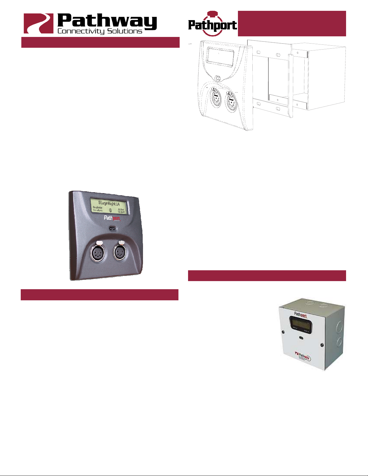
C-SERIES NODE (6201, 6202, 6203)
Disconnect all power before proceeding with the installation. If the node has been pre-configured, check the
temporary label to ensure the node is being installed in
the correct location.
C-series nodes should be installed in standard twogang masonry deep backboxes (ears in) for flushmounting or, for surface mounting, in Pathport surface
mount backboxes, part number 6901. Use of other surface mount backboxes is not recommended. Check the
backbox for obstructions or any foreign material. The
backbox should be clean and empty of debris. Install the
in-line jack provided, if necessary.
Attach the Pathport trim ring to the backbox with the 4
screws provided. Do not over-tighten or distort the shape
of the trim ring.
Inspect the node and make sure all components, including the printed circuit boards, are secure. Note that it is
normal to see exposed metal on the mating connectors.
If the backbox contains an RJ45 female punchdown
connector, use the male-to-male jumper (included) to connect it to the node. Otherwise, plug the male RJ45 pigtail
D-SERIES NODE (6225)
Disconnect all power before proceeding with installa-
tion.
D-series nodes are surfacemount enclosures, designed for
conduit-enclosed cable connection to permanently installed
equipment such as dimmers
and relay cabinets. D-series
nodes are shipped attached to
their backboxes.
First, remove the two screws
holding the faceplate to the
backbox. Keep the screws for
later use. Gently remove the faceplate and the attached
printed circuit boards. Put the faceplate back into its shipping carton or other container.
Determine the location of the backbox in relation to the
incoming and outgoing conduit lines. Remove the appropriate knockouts then securely mount the backbox to the
wall using appropriate fasteners. If the backbox must be
installed prior to the completion of the conduit and wiring
runs, label the backbox and the container holding the removed faceplate. Store the container in a safe location.
Make sure the two faceplate screws are stored in the
Page 3

Installer’s Guide
same box.
Attach the conduit runs to the enclosure using standard
connectors (not supplied). The backbox should be clean
and free of obstructions or foreign materials. Inside, there
should be one Cat5 wire with a female RJ45 punchdown
connector (if necessary, install the mini-jack included) and
one or two cables for the DMX connections, ending in
bare wires. Identify which cable is for DMX Universe A
and which is for DMX Universe B.
Retrieve the faceplate from the storage container. Inspect it for damage and to ensure the printed circuit
boards are securely fastened.
Using the XLR pin-out chart at the start of this guide,
attach the cable for DMX Universe A to the terminal block
marked DMX Port A. Repeat, if necessary, for DMX Port
B. If Cat5 cable is being used to complete the DMX run,
use the Cat5 pin-out guide instead.
Using the male-to-male jumper, connect the female
RJ45 connector to the connector on the back of the circuit
board of the node.
If local power is required, see the note at end of this
guide.
Gently position the faceplate on the backbox until the
screw holes line up, while taking care that no wiring is
pinched, excessively bent or stressed inside the box. Using the original two screws, reattach the faceplate. Do not
over tighten.
The node is ready to be powered up.
PATHPORT UNO (6101SS/BL, 6102SS/BL)
Disconnect all power before proceeding with installation.
Pathport Uno single-port nodes are
designed to be installed in standard
masonry deep backboxes (ears in) for
flush mounting, or deep (minimum
58mm or 2.25”) surface mount backboxes.
If the node has been pre-configured,
check the temporary label to ensure
the node is being installed in the correct location.
Uno nodes can be permanently set
to a specific DMX universe, 1 through
4, by use of a jumper on the back
edge of the circuit board. If the system designer has not
given specific instructions about the setting, then leave
the jumper in the NET position.
Each Uno node ships with additional serial number
stickers. Do not lose these stickers. Because Unos do
not have a faceplate screen, tracking serial numbers and
their locations is necessary to configure the system. Losing track of this information will add considerable time to
commissioning.
As each node is installed, remove one of the additional
serial number stickers and place it on the Installation
Record Sheet included with each Uno. Write down the
location, jumper settings and any other comments. A
second sticker can be placed on the face of the Uno for
identification during commissioning. This sticker can be
easily removed and discarded when no longer needed.
Once this information is recorded, check the backbox for
obstructions or foreign material. The backbox should be
clean and empty of debris. Inspect the Uno and make
sure all components are securely fastened and that the
printed circuit boards are intact.
If the back backbox contains an RJ45 female punchdown connector, use a male-to-male jumper to connect it
to the node. Otherwise, plug the male RJ45 pigtail directly
into the connector on the back of the node. Attach the
green ground wire to the ground screw in the backbox.
Gently insert the Uno straight into the backbox and
screw it into place with the long mounting screws provided. Place the cover plate over the installed Uno and use
the two short screws to fasten the cover plate. Do not
over-tighten these screws.
The Uno is ready to be powered up.
PATHPORT EDIN (1011, 1012, 1014)
Disconnect all power before proceeding.
Each Pathport eDIN ships with additional serial number
stickers. Do not lose these stickers. Because Pathport
eDINS are intended for installation within enclosures,
maintaining a log of serial numbers and their locations is
necessary to configure the system. Losing track of this
information will add considerable time to commissioning.
As each node is installed, remove one of the additional
stickers and place it on the Installation Record Sheet included with each Pathport eDIN. Write down the location,
jumper settings and any other relevant comments.
A second serial number sticker may be placed on the
exterior cover of the enclosure as a further identifying aid
during commissioning. This sticker can easily be removed
and discarded when no longer needed.
Securely mount DIN rail (if not already installed in the
enclosure). Hook the upper slots on the back of the plastic extrusion to the DIN rail and then gently but firmly
press on the bottom front corners of the extrusion to snap
the module onto the rail. Do NOT press directly on the
PCB card itself.
Attach the DMX wiring to the terminal strip output connector(s). If the Pathport eDIN is using an auxiliary power
supply, connect the terminal strip. Observe DC polarity.
Attach the network cable to the RJ45 connector marked
Ethernet. The node is ready to be powered up. Both auxiliary power and PoE can be connected simultaneously
without damaging the Pathport eDIN.
Pathport 1011 nodes may be set permanently to a specific DMX universe, 1 through 4, by use of a dip switch
block on the circuit board. If the system designer has not
given specific instructions about this setting, all switches
should be left in the OFF position.
Page 4

Installer’s Guide
PATHPORT PORTABLE UNO (6151, 6152)
The Portable Uno may be powered using Power-overEthernet or a 24VDC supply with a 2.5mm center-positive
barrel connector.
To attached the hanging bracket (included), remove the
top two screws from either end of the portable enclosure
(four screws altogether), position the hanging bracket
over the top of the enclosure, then use the same screws
to attach the bracket to the enclosure.
The hanging bracket has a 1/2” (12.5mm) hole suitable
for a C-Clamp or other hanger (not included).
PATHPORT TOURING EDITION (6182)
The Pathport Touring Edition operates on Power-overEthernet during normal operation, but may be configured
using power from a 9V battery (included).
Once connected to a PoE source, the Pathport Touring
Edition is ready for use.
PATHPORT QUATTRO (6311, 6312, 6316)
The Pathport Quattro operates on Power-over-Ethernet
or an auxiliary 24VDC supply with a 2.5mm centerpositive barrel connector (supply not included).
Once powered up, the Pathport Quattro is ready for
use. There is no on/off switch.
The Pathport Quattro is designed for installation in a
standard EIA 19” rack, with the LCD and encoder facing
out. Attach the rack ears (included) to either side of the
enclosure using the Phillips screws provided (two per
ear). Attach the Pathport Quattro to the rack using standard rack screws (not included).
A joiner is included to allow two Quattros to be installed
side-by-side in 1RU of rack space. Wall and truss mount
adapters are available as accessories.
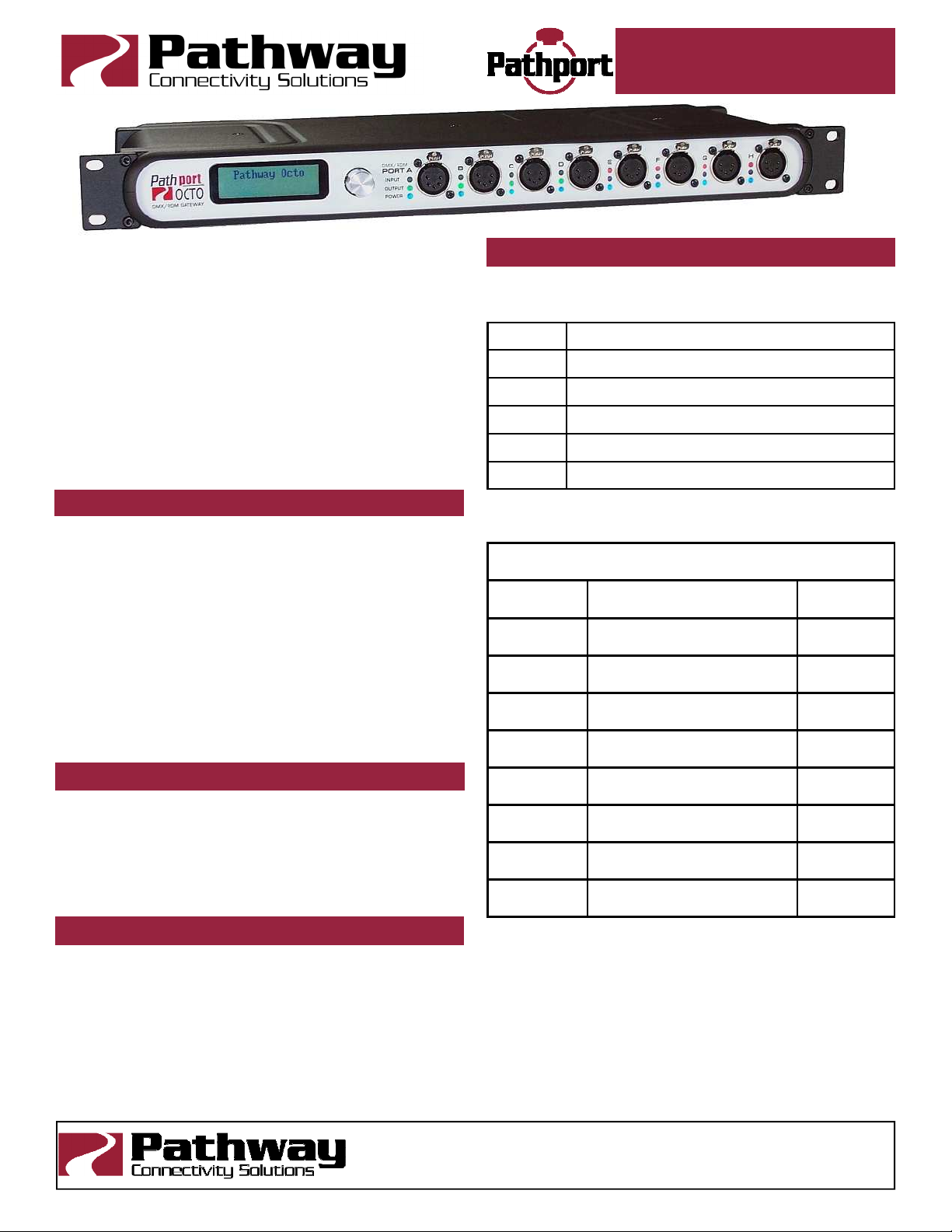
PATHPORT OCTO (6401, 6402, 6403, 6406, 6407)
The Pathport Octo will only operate on wall power, accepting an input voltage between 85-250VAC at either 50
or 60 Hz. The AC outlet shall be near the equipment and
shall be easily accessible. There is no on/off switch. This
equipment relies on building installation overcurrent protection.
Once powered up, the Pathport Octo is ready for use.
The Pathport Octo is designed for installation in a
standard EIA 19” rack, with the LCD and encoder facing
out. Attach the rack ears (included) to either side of the
enclosure using the Phillips screws provided (two per
ear). Attach the Pathport Octo to the rack using standard
rack screws (not included).
Wall and truss mount adapters are available as accessories.
PATHPORT VIA 10+1 GIGABIT SWITCH (6730)
The Pathport VIA will only operate on wall power, accepting an input voltage between 85-250VAC at either 50
or 60 Hz. The AC outlet shall be near the equipment and
shall be easily accessible. There is no on/off switch. This
equipment relies on building installation overcurrent protection.
Once powered up, the Pathport VIA is ready for use.
The Pathport VIA is designed for installation in a standard EIA 19” rack, with the LCD and encoder facing out.
Attach the rack ears (included) to either side of the enclosure using the Phillips screws provided (two per ear). Attach the Pathport VIA to the rack using standard rack
screws (not included).
Wall and truss mount adapters are available as accessories.
LOCAL POWER
All C-series, D-series and R-series nodes, Pathport
eDINS and Unos shipped since mid-2010, may be connected to an external power supply, when Power-overEthernet is not available. Each node will require a supply
between 18 and 50VDC and consume no more than 4
watts of power.
With the power supply turned off, connect the bare wire
ends to the 2-wire terminal block (included). Slip the
block over the pins marked V+ and V-, observing polarity.
On C- and D-series nodes and Uno nodes, these pins are
mounted on the circuit board. On the Pathport eDIN, use
the terminal block marked for Power In, and use the V+
and V- positions. Observe polarity.
Check all wiring, then connect the power supply to the
mains power. Pathway does not provide external local
power supplies. The AC connection required should be
provided in accordance with local regulations.
OPERATING ENVIRONMENT
All Pathport nodes are designed for indoor use in a dry
location. To maximize equipment life and minimize unreliability and sudden failure, the following environment
should be maintained:
• ambient temperature extremes: -10 to +50 degrees C
• operating temperature: 0 to +40 degrees C
• relative humidity: 10 – 95%, non-condensing
• general conditions: clean, dust-free
CONFIGURATION
Pathport configuration is done with Pathport Manager 5
software or through the front panel user interface on
some models. Please refer to the Pathport Manager
manual, or the individual model’s manual, for instructions
on device configuration.
WARNING
Except for the IEC chassis plug marked for AC input on
the Pathport Quattro, the Pathport Octo and the Pathport
VIA, all ports on all Pathport Nodes are to receive low
voltages only.
All ports intended for DMX or other EIA485 signals
shall not be connected to anything other than low voltage
signal sources or receivers.
Attaching anything other than low voltage sources to
the data ports may result in severe equipment damage,
and personal injury or death.
 Loading...