

Page 1
Model 1009 • DMX/RDM Splitter Manual
OVERVIEW
Pathway eDIN DMX/RDM Splitters support the
bi-directional communications necessary for E1.20
Remote Device Management in DMX512
installations requiring star-wiring. Full optoisolation between all ports adds maximum
protection against common mode voltages or
ground faults for connected equipment.
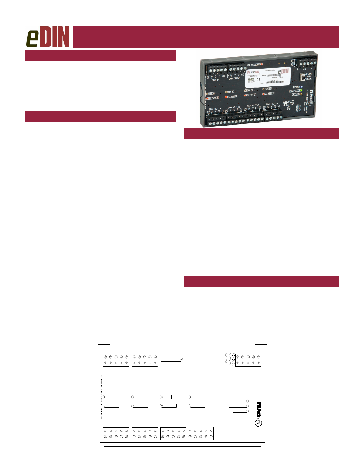
CONNECTIONS
The eDIN DMX/RDM Splitter features terminal strips
that can be removed from the card to facilitate easy wiring installation or replacement. Make the following connections, WITH THE POWER TURNED OFF, and observe ESD precautions by ensuring the installer is
properly grounded before handling the module.
POWER
The DMX/RDM Splitter is designed to run on a range of
voltages from 9-30 volts DC. Each DMX/RDM Splitter
module requires 6 watts. Observe the correct polarity
when connecting to V+ and V-. A second set of terminals are provided as a DC power-through connection to
other eDIN modules. The EARTH GND terminal must
be connected to the enclosure’s chassis or electrical
ground terminal to ensure EMC compliance.
DMX
DMX connections consist of a shield and a data pair. An
optional second auxiliary data pair is also occasionally
employed. DMX IN usually comes from a control console, Pathport® node, architectural controller or optosplitter. DMX THRU provides a means to daisy-chain
DMX to other eDIN modules.
the DMX IN terminal. Connect the cable shield or common to the SHLD COM terminal. Observe the same
polarity convention throughout the system while connecting the four outputs.
Connect wires for DATA2+ and DATA2– to D2+
and D2–, if desired. It is not necessary to connect these
wires for DMX or RDM to function.
Connect DATA+ and DATA- to D1+ and D1– on
STATUS INDICATORS
POWER IN Blue. Glowing steadily indicates power
PROCESSOR Green. Glowing steadily indicates pro-
DMX
INPUT
ISO POWER IN Red. Internally isolated power supply
ISO POWER
A/B/C/D
RDM A/B/C/D Amber. Flickering indicates presence
RDM CONTROLLER
A compliant RDM controller must be used to get and set
RDM information and commands. The eDIN DMx/RDM
Splitter does not provide controller functions, but simply
allows RDM messages within a star-wiring network.
A Pathport node and suitable software can be
used to provide RDM controller functions.
supply OK; off indicates no power.
cessor is OK; off when POWER IN is
lit indicates processor failure.
Amber. Glowing steadily indicates
data signal received; off indicates no
signal present.
for input processing working correctly.
Off means no power.
Red. Internally isolated power supply
to that output port is working correctly.
Off means no power to that port.
of RDM data packets. Off indicates
no RDM activity on the network.
ISO INPUT PWR
SHLD
COM
SHLD
D1+
D2+
D2-
DMX IN
RDM A RDM B RDM C RDM D
ISO PWR A ISO PWR B ISO PWR C ISO PWR D
DMX OUT A DMX OUT B DMX OUT C DMX OUT D
COM
SHLD
D1-
D1+
D2+
D1-
COM
SHLD
D2+
D2-
D1+
D2-
DMX THRU
D1+
D1-
COM
D1-
COM
SHLD
D1+
D2-
D1-
D2+
COM
SHLD
D1-
D2-
D2+
V-V+V-
V+
EARTH
GRD
4 - PORT DMX/RDM SPLITTER
POWER
PROCESSOR
DMX/RDM
D2-
D1+
D2+
Page 2
Model 1009 • DMX/RDM Splitter Manual
DMX TERMINATION
The eDIN DMX/RDM Splitter is internally terminated and
does not require any further termination at the module.
However, the last DMX device on each output
leg must still be properly terminated in accordance with
the E1.11 DMX512-A standard, to ensure correct device
operation.
DMX THRU CONNECTOR
The DMX Thru connector is an active pass through and
fully supports RDM. In effect, it is a fifth output port. If
power is lost to the module, the DMX Thru connector
will no longer function.
Due to timing restrictions in the RDM standard,
no more than seven (7) eDIN DMX/RDM Splitters may
be daisy-chained together in one run.
E1.20 REMOTE DEVICE MANAGEMENT
ANSI E1.20 Remote Device Management (RDM) is an
open standard data protocol that provides DMX512-A
networks with the option of bi-directional communications (aka ’talkback’). By using half-duplex data communications, RDM operates over the same wire pair
(pins 2 and 3) as DMX, ensuring backwards compatibility with all DMX installations.
SYSTEM TOPOLOGY
System layout is critical for successful use of the RDM
standard. Wire type and installation methodology must
be correct as the timing restrictions required by RDM
are much stricter than for DMX.
RDM devices are classified as ‘controllers’,
‘responders’ or ‘in-line’ devices. Only one controller
may be active on a given network. When the controller
issues a command, it listens for a response within a
prescribed time. During this period, ’in-line’ devices like
the eDIN DMX/RDM Splitter prepare to pass data back
to the controller.
integrity of the DMX signal, a maximum of seven in-line
devices are allowed between the controller and an output with a responder attached.
The eDIN DMX/RDM Splitter is considered an
‘in-line’ device. The signal path may never include
more than seven eDIN DMW/RDM Splitters. Anything
greater will prevent devices further downstream from
being able to respond.
Due to timing constraints imposed to ensure
Pathway Connectivity Solutions
103-1439 17Avenue SE Calgary AB Canada T2G 1J9
tel (403) 243-8110 fax (403) 287-1281
WARNING: Do not install other RDM responders
between the controller and the #1009 DMX/RDM
Splitter, or between the Thru connector on one
Spliter and the DMX IN on the next.
DMX WIRING PIN OUT REFERENCE
Standard RS422/485 Conductor Pin Outs
(ie Belden, Proplex, etc)
Terminal Pin Wire Color Manufacturer Specific
Pin 1 Shield
Pin 2 Data – (pair 1 complement)
Pin 3 Data + (pair 1 true)
Pin 4 Optional Data – (pair 2 complement)
Pin 5 Optional Data + (pair 2 true)
Cat5, Cat5e and Cat6 Wiring Pin Outs
Wire Color and # Function
White/orange (1) Data + 3
Orange (2) Data – 2
White/green (3) Optional Data + 5
Green (6) Optional Data – 4
Blue (4) Unused/unconnected
White/blue (5) Unused/unconnected
White/brown (7) Data signal common 1
Brown (8) Data signal common 1
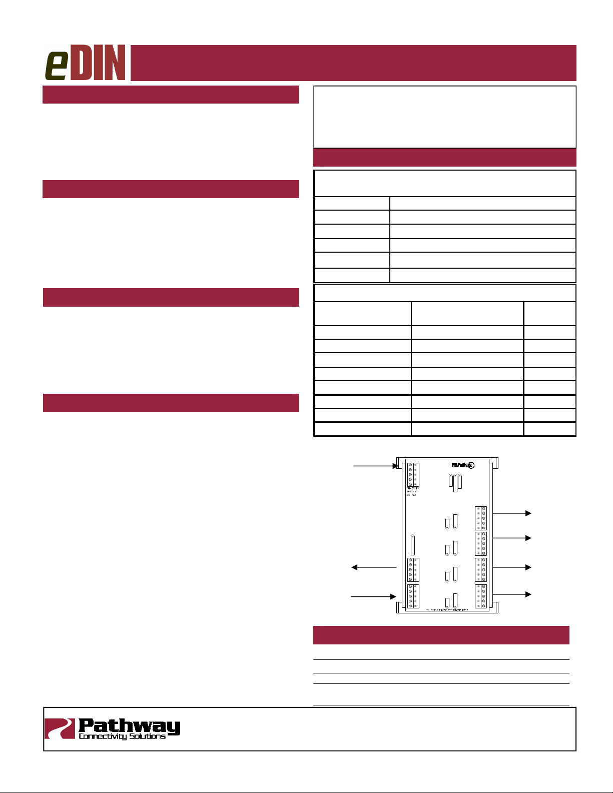
Power In
Signal Thru to
other
Signal In from
Controller
V+
V-
VV+
EARTH
GRD
4 - PORT DMX/RDM SPLITTER
POWER
DMX/RDM
PROCESSOR
Signal Out to
DMX/RDM Gear
D2+
D2D1+
D1-
COM
SHLD
D2+
D2D1+
D1-
ISO INPUT PWR
SHLD
COM
D1D1+
D2-
DMX THRU
D2+
SHLD
COM
D1D1+
DMX IN
D2D2+
COM
SHLD
D2+
D2D1+
D1-
COM
SHLD
D2+
D2D1+
D1-
DMX OUT A DMX OUT B DMX OUT C DMX OUT D
COM
RDM A RDM B RDM C RDM D
ISO PWR A ISO PWR B ISO PWR C ISO PWR D
SHLD
Pin
Number
SPECIFICATIONS
P
OWER SUPPLY
I
NPUT SIGNAL
O
UTPUTS
C
ONNECTIONS
S
IZE
:
: 9-30 VDC, 6W
: ANSI E1.11 DMX512-A, ANSI E1.20 RDM
: ANSI E1.11 DMX512-A, ANSI E1.20 RDM
Two piece compression screw terminals, 16 - 24 AWG
:
3.5” x 6.25” x 1.25” (90mm x 160mm x 35mm)
support@pathwayconnect.com
www.pathwayconnect.com
docrev.3
Printed in Canada
9/15
 Loading...