

Page 1
Model 1004
rev5
• DMX Demultiplexer Manual
OVERVIEW
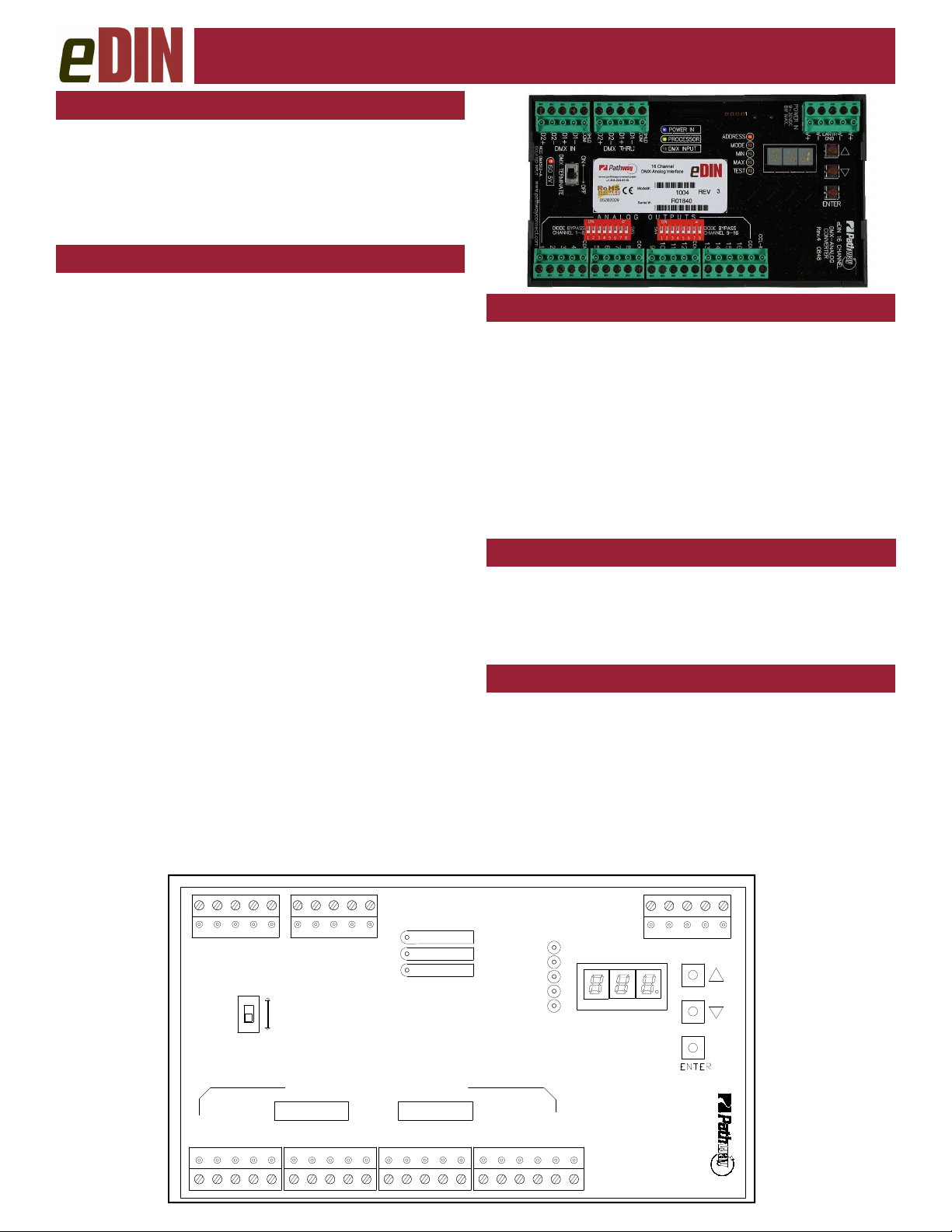
Pathway eDIN Demultiplexer converts DMX512
signals into 16 channels of analog control voltage.
The Demultiplexer can also control Mark 7–type
fluorescent ballasts, solid state relays or LEDs.
The module is RDM discoverable and configurable.
CONNECTIONS
The eDIN Demultiplexer features terminal strips that can
be removed from the card to facilitate easy wiring installation or replacement. Make the following connections,
WITH THE POWER TURNED OFF.
POWER
The Demultiplexer will operate on a range of voltages
from 9-30 volts DC. Each eDIN module requires 250mA.
Observe the correct polarity when connecting to V+ and
V-. A second set of terminals are provided as a thru connection to other eDIN modules. The EARTH GND terminal must be connected to the enclosure’s chassis or electrical ground terminal to ensure EMC compliance.
DMX
DMX connections consist of a shield and a data pair. A
optional second auxiliary data pair is also occasionally
employed. DMX IN usually comes from a control console,
Pathport® node, architectural controller or opto-splitter.
DMX THRU provides a means to daisy-chain DMX to
other eDIN modules. Connect DATA+ and DATA- to D1+
and D1-. Observe the same polarity convention throughout the system. Connect the cable shield or common to
the SHLD COM terminal.
ANALOG OUTPUTS
Sixteen analog output terminals are provided in groups of
four, each with a common terminal. All common terminals
are internally connected, so only one needs to be tied to
the device being controlled. Outputs are rated up to 15
volts DC, 10mA per channel. Maximum wire run is 150
meters (500 ft.).
STATUS INDICATORS
POWER IN Blue. Glowing steadily indicates power
supply OK; off indicates no power.
PROCESSOR Green. Glowing steadily indicates proces-
sor is OK; off when POWER IN is lit indicates processor failure.
DMX
INPUT
Amber. Glowing steadily indicates data
signal received; off indicates no signal
present.
FUNCTION Amber. Indicates the menu function asso-
ciated with the numeric display.
DMX TERMINATE
DMX rules require the final device in line have a terminating resistor. If no devices or modules are connected to the
DMX THRU terminal, the DMX TERMINATE switch
should be ON. If other devices or modules are connected
to DMX THRU, the DMX TERMINATE should be OFF.
CONFIGURATION
To configure, first press the ▲ or ▼ buttons to select the
desired function, as indicated by a lit LED next to ADDRESS, MODE, MIN, MAX, or TEST. Once chosen,
press and hold the ENTER button until a dot appears on
the right hand display. The function is now editable.
When done editing a parameter, press ENTER. The
dot will disappear, the new value will be saved and the
unit will be ready for operation.
D2+
D2-
D1+
DMX IN
DMX
TERMINATE
3
214
6 Watts MAX
9-30 VDC
POWER IN
COM
SHLD
COM
D1-
D2+
D2-
DMX THRU
ON
OFF
A N A L O G O U T P U T S
DIODE SHUNT
CHANNEL 1-8
COM
214
SHLD
D1+
D1-
COM
3
POWER IN
PROCESSOR
DMX INPUT
DIODE SHUNT
CHANNEL 9-16
3
214
V-
GRD
CONVERTER
V+
eDIN 16 CHANNEL
DMX - ANALOG
V+
ADDRESS
MODE
MIN
MAX
TEST
COM
3
214
CCL-IN
COM
V-
Rev.4
Page 2

Model 1004
rev 5
● DMX Demultiplexer Manual
SET DMX ADDRESS
Once in ADDRESS edit mode, press ▲ or ▼ to change
the start address to the desired value. Press ENTER to
save the address. Valid addresses range from 1 to 512.
SET OPERATING MODE
Once in MODE edit, choose from the following:
Mode 1: 0—10VDC Output (MAX will read 158)
Mode 2: 0—5 VDC Output (MAX will read 79)
Mode 3: 0—15VDC Output (MAX will read 237)
Mode 4: 0—2.5 VDC Output (MAX will read 40)
Mode 5: Custom D-to-A (set your own voltage)
Mode 6: 8 Channel EFBC (see below)
Mode 7: Non-Dim (see below)
SET MIN AND MAX VOLTAGE OUTPUT LEVELS
To set a custom output voltage, confirm the DMX start
address is set to 1. Connect a voltmeter between output
1 and COM on the card. Connect a DMX source to DMX
IN. Using your source, vary the DMX level on channel 1
and confirm that the voltage output is changing. Set the
DMX level to full.
Use the ▲ and ▼ buttons and ENTER to select MAX
for editing. Use ▲ and ▼ while observing the output on
your voltmeter. Once the voltage is at the level you desire, press ENTER to save. Repeat this process to set a
MIN level. Valid MIN levels are between 0 and 254.
Valid MAX levels are between 1 and 255. 255 roughly
corresponds to an output of 16VDC.
Custom values are retained in Mode 5 only. Changing
the output voltage in modes 1 to 4 will force the card into
Mode 5. MIN and MAX are not editable in Modes 6 and 7.
ELECTRONIC FLUORESCENT BALLAST CONTROL
Mode 6 allows control of up to eight circuits of Mark 7type ballasts, with a maximum of 20 ballasts on each circuit. Two channels on the card are required for each circuit. The channels are paired, 1 with 9, 2 with 10, and so
on. The lower channel provides 0-10VDC dimming control, while the higher acts as a non-dim, switching at 10%,
and should be connected to a solid state relay controlling
the circuit’s AC supply. All blocking diodes must be
shunted (by-passed) in this mode.
NON-DIM CONTROL
Mode 7 provides non-dim control of solid state relays or
LEDs. At a DMX level of 0%, each channel outputs
+10VDC The output voltage drops to zero when DMX
passes 50%. All blocking diodes must be shunted
(bypassed) in this mode.
TEST MODE
Using the ▲ and ▼ buttons, each output will be toggled
on and off. The output number is shown on the right hand
display. DMX is ignored while in TEST mode.
CCL PIN (PANIC INPUT)
Shorting the CCL pin to COM will drive all outputs to full.
The CCL input overrides the DMX input level.
SELF-TEST
Press the ▲ button while turning power on to enter selftest. All LEDs will flash sequentially. The display will cycle 0 through 9, then show the serial number and firmware version. Cycle power to end self-test.
E1.20 REMOTE DEVICE MANAGEMENT
The eDIN 1004 Demultiplexer is fully compliant with ANSI
E.20 Remote Device Management as a responder device.
DIODE SHUNTS
The behavior of the diode shunts is dependent on the
module’s revision level. The revision number is shown on
the product label, next to the part number.
The diodes prevent the control signal from back-feeding
into the output and damaging the module. The diodes
must be removed from the circuit to allow sinking control.
The 16 dip switches are wired as shunts, allowing the diodes to be engaged or disengaged output-by-output.
REV 4 and below: The blocking diodes are engaged
by default. With the shunt switches in the “off” position,
the diodes will prevent current backflow. This is the correct arrangement for driving analog dimmers. With the
shunts in the “on” position, the diodes are by-passed.
This is the correct arrangement for sinking control of
EFBCs and LED dimmers.
REV 5 and higher: The blocking diodes are by-passed
by default. With the dip switches in the “off” position, current will backflow through the card. This is the correct
arrangement to allow sinking control of EFBCs and LED
dimmers. With the dip switches in the “on” position, the
diodes will block backflow current. This is the correct arrangement for driving analog dimmers.
SPECIFICATIONS
P
OWER SUPPLY
I
NPUT SIGNAL
O
UTPUTS
O
UTPUT RATING
E
XCEEDING THESE RATINGS MAY RESULT IN DAMAGE TO THE DEVICE
C
ONNECTIONS
S
IZE
:
: 9-30 VDC, 2.5W
: ANSI E1.11 DMX512-A, ANSI E1.20 RDM
: 16 analog 0-10VDC nominal, maximum 16VDC
: 10MA current drive per channel sourcing or sink-
ing, diode isolated
Two piece compression screw terminals, 16 - 24 AWG
:
3.5” x 6.25” x 1.25” (90mm x 160mm x 35mm)
rev.5
Pathway Connectivity Inc
103-1439 17Avenue SE Calgary AB Canada T2G 1J9
tel (403) 243-8110 fax (403) 287-1281
support@pathwayconnect.com
www.pathwayconnect.com
Printed in Canada
11/11
 Loading...