

Page 1
Model 1011 Pathport Node Installation
OVERVIEW
The Pathport® eDIN one-port node provides the
full functionality of other Pathport nodes, in a
compact, DIN-rail mountable format. System
integrators can now easily put a fully
customized universe of DMX where it’s needed.
Ideal for use in NEMA enclosures. Fully
compatible with other eDIN modules.
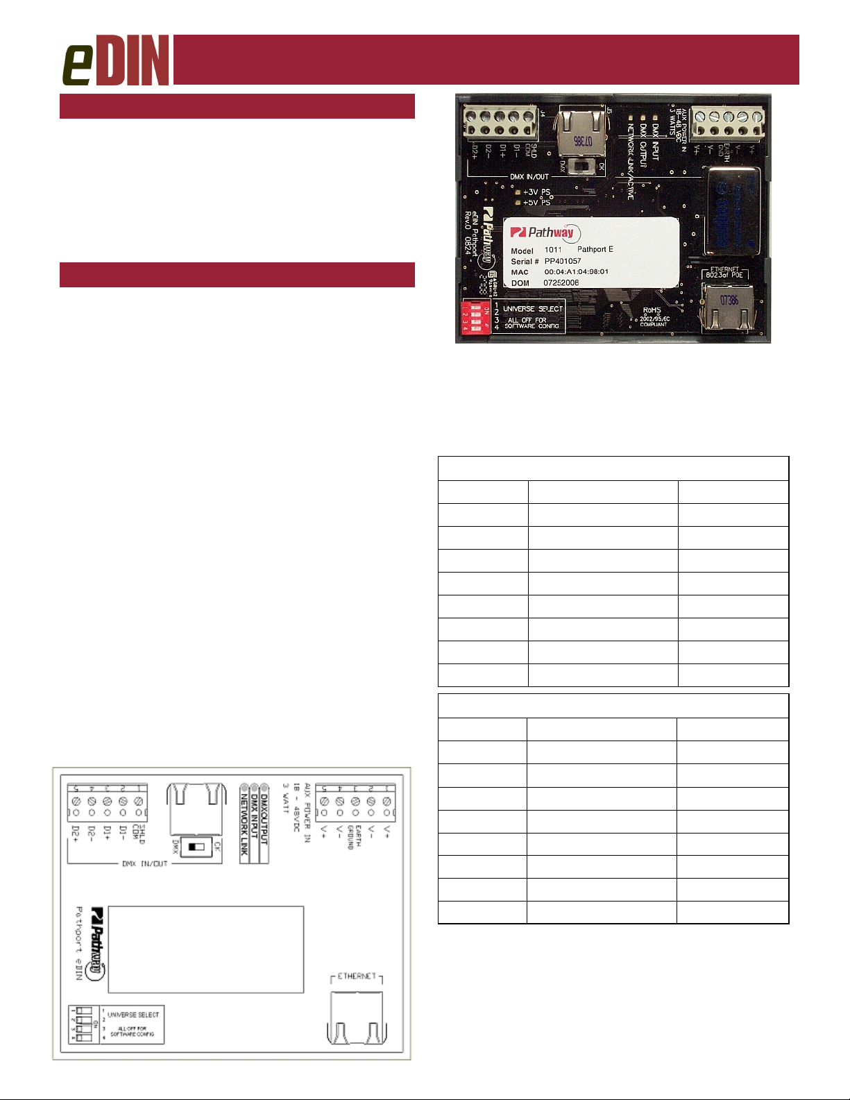
CONNECTIONS
The Pathport eDIN features terminal strips that can be
removed from the card to facilitate easy wiring for auxiliary power and DMX. DMX can also be wired to an
RJ45 jack, while a second RJ45 jack is used for
Ethernet connection. Make the following connections,
WITH THE POWER TURNED OFF:
Power
The Pathport eDIN is designed to run on either Powerover-Ethernet (PoE), or on an auxiliary power suppy
providing between 18 and 48 volts DC. The node will
draw 3 watts.
If an auxiliary supply is used, observe the polarity when
connecting V+ and V-. A second set of terminals are
provided so power may be daisy-chained to other cards.
These terminals are not energized when the node is run
on PoE. The EARTH GROUND terminal must be connected to the enclosure’s chassis or electrical ground
terminal to ensure EMC compliance.
DMX - Terminal Strip
DMX connections consist of a shield and a data pair. A
optional second auxiliary data pair is also occasionally
employed. Connect DATA+ and DATA-, to D1+ and
D1-. Observe the same polarity convention throughout
the system. Connect the cable shield or common to the
SHLD COM terminal.
DMX - RJ45 Connection
Refer to the chart below for wiring pinouts for the RJ45
connector. The RJ45 is manually switchable between
an ESTA standard DMX pinout and a pinout suitable for
Philips Solid-State Lighting (Color Kinetics) products
using RJ45 connectors for DMX input.
E1.27-2 Cat5/6 Pinout for DMX 512A
DMX Signal Cat5/6 Wire Color & # XLR Pin #
Data 1 + 1 - White/Orange 3
Data 1 - 2 - Orange 2
Data 2 + 3 - White/Green 5
Data 2 - 6 - Green 4
not used 4 - Blue
not used 5 - White/Blue
Shield/COM 7 - White/Brown 1
Shield/COM 8 - Brown 1
Cat5/6 Pinout for Color Kinetics
DMX Signal Cat5/6 Wire Color & # XLR Pin #
Data 1 - 1 - White/Orange 2
Data 1 + 2 - Orange 3
Shield/COM 3 - White/Green 1
not used 6 - Green
not used 4 - Blue
not used 5 - White/Blue
not used 7 - White/Brown
not used 8 - Brown
ETHERNET
All network wiring should follow standard Ethernet rules
and be installed by a qualified person. As part of the
installatin, all wiring should be certified under the TIA/
EIA-568 standard.
For further information, refer to the Pathport System
Design and Layout Guide.
Page 2

ESTA
ENTERTAINMENT SERVICES &
TECHNOLOGY ASSOCIATION
Model 1011 Pathport Node Installation
INSTALLATION
Disconnect all power before proceeding with installation.
Pathport eDINs can be set permanently to a specific
DMX universe, 1 through 4, by use of a dip switch block
on the lower left hand corner of the circuit board. Only
one universe may be specified via the dip switches.
If the system designer has not given specific instructions
about this setting, all switches should be left in the OFF
position, allowing the universe to be set remotely using
software installed on a computer. Dip switch settings
override the ability to set the DMX universe via software.
Each Pathport eDIN ships with additional serial number
stickers. Do not lose these stickers. Because Pathport
eDINS are intended for installation within enclosures,
maintaining a log of serial numbers and their locations is
necessary to configure the system. Losing track of this
information will add considerable time to commissioning.
As each node is installed, remove one of the additional
stickers and place it on the Installation Record Sheet
included with each Pathport eDIN. Write down the location, jumper settings and any other relevant comments.
A second serial number sticker may be placed on the
exterior cover of the enclosure as a further identifying
aid during commissioning. This sticker can easily be
removed and discarded when no longer needed.
Securely mount DIN rail (if not already installed in the
enclosure). Hook the upper slots on the back of the
plastic extrusion to the DIN rail and then gently but
firmly press on the bottom front corners of the extrusion
to snap the module onto the rail. Do NOT press directly
on the PCB card itself.
Attach the DMX wiring either to the terminal strip or the
RJ45 jack. Do not use both simultaneously.
If the Pathport eDIN is using an auxiliary power supply,
connect the terminal strip, after checking that polarity is
being observed. The card will boot up.
Attach the network cable to the RJ45 connector marked
Ethernet. Because good wiring practice requires building wire to terminate with a female connector, typically a
short (12”/30cm) male-to-male jumper is used. If PoE is
being used, the card will boot up. Both auxiliary power
and PoE can be connected simultaneously without damaging the Pathport eDIN.
The system is now ready for testing.
STATUS INDICATORS
+3V PS Blue. Steady glow indicates 3V power
supply is OK. Off indicates no power.
+5 PS Blue. Steady glow indicates 5V power
supply is OK. Off indicates no power.
DMX Output Amber. Steady glow indicates node is
actively outputting DMX. Off indicates
no DMX output.
DMX Input Green. Steady glow indicates node is
receiving active DMX. Off indicates
no incoming DMX signal.
Network Link Green. Flickering glow means active
Ethernet network link. Off indicates no
network link.
DEFAULT SETTINGS
The Pathport eDIN ships as an DMX output node with
the following Ethernet receive protocols enabled: Pathport, Strand Shownet, ETC Net2, streaming ACN and
ArtNet. Channel information in DMX universe 1, placed
on the network using any of these protocols, will cause
the eDIN node to actively output DMX.
FURTHER CONFIGURATION
A large number of values and parameters may be customized for the Pathport eDIN, including port direction,
output channel patch, input universe number, the transmit and receive protocols, and DMX speed. Network
values such as IP address and subnet mask are also
customizable by the user.
Detailed node configuration and overall network system
management are done using Pathport Manager software, which is freely available from our website,
www.pathwayconnect.com
WARNING REGARDING RJ45 CONNECTORS
The use of RJ45 connectors for DMX equipment should
be restricted to patch bays in access-controlled rooms
or to enclosure-mounted interfaces. The connection of
DMX equipment to non-DMX equipment may result in
serious equipment damage, fire hazard and/or personal
injury. To help prevent this possibility, when using Cat
5/6 wire for DMX transmission, wires 4 and 5 should be
turned back and capped rather than connected.
SPECIFICATIONS
P
OWER SUPPLY
D
ATA
S
E
THERNET
: 18 -- 48 VDC, 3 watts or 802.3af PoE
IGNAL
: ANSI E1.11 DMX512-A, ANSI E1.20 RDM
802.3 10baseT
rev.1, ver.1
Pathway Connectivity
#103 - 1439 17 Avenue SE Calgary AB, Canada T2G 1J9
tel (403) 243-8110 fax (403) 287-1281
support@pathwayconnect.com
www.pathwayconnect.com
Printed in Canada
11/08
 Loading...