

Page 1
Model 1009 • DMX/RDM Splitter Manual
OVERVIEW
Pathway eDIN DMX/RDM Splitters allow the bidirectional communications necessary for E1.20
Remote Device Management in DMX512
installations requiring star-wiring. Full optoisolation between all ports adds maximum
protection against common mode voltages or
ground faults for connected equipment.
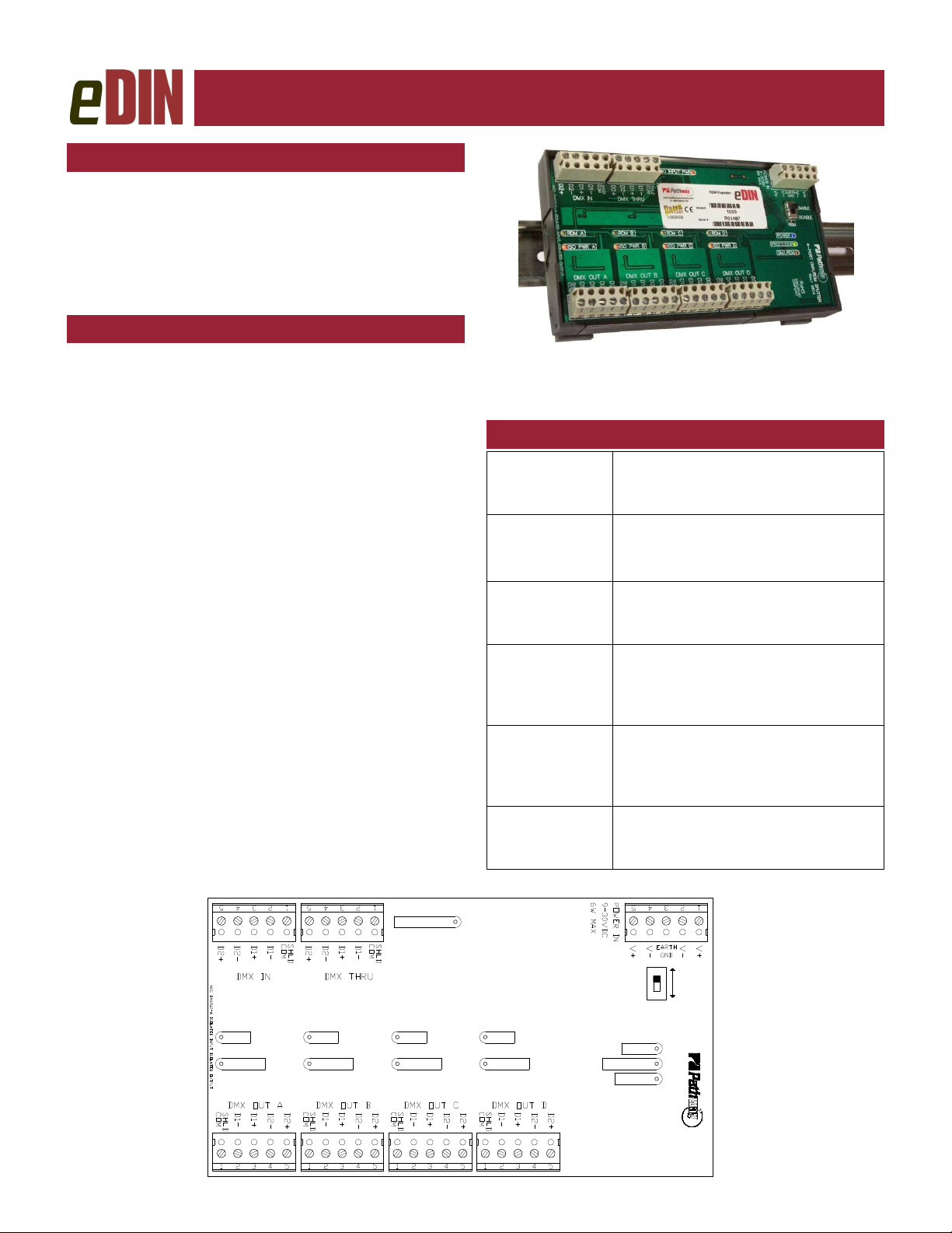
CONNECTIONS
The eDIN DMX/RDM Splitter features terminal strips
that can be removed from the card to facilitate easy wiring installation or replacement. Make the following connections, WITH THE POWER TURNED OFF, and observe ESD precautions by ensuring the installer is properly grounded before handling the module.
POWER
The DMX/RDM Splitter is designed to run on a range of
voltages from 9-30 volts DC. Each eDIN module requires 6 watts. Observe the correct polarity when connecting to V+ and V-. A second set of terminals are provided as a thru connection to other eDIN modules. The
EARTH GND terminal must be connected to the enclosure’s chassis or electrical ground terminal to ensure
EMC compliance.
DMX
DMX connections consist of a shield and a data pair. A
optional second auxiliary data pair is also occasionally
employed. DMX IN usually comes from a control console, Pathport® node, architectural controller or optosplitter. DMX THRU provides a means to daisy-chain
DMX to other eDIN modules.
the DMX IN terminal. Connect the cable shield or common to the SHLD COM terminal. Observe the same
polarity convention throughout the system while connecting the four outputs.
Connect DATA+ and DATA- to D1+ and D1– on
Connect wires for DATA2+ and DATA2– to D2+
and D2–, if desired. It is not necessary to connect these
wires for DMX or RDM to function.
STATUS INDICATORS
POWER IN
PROCESSOR
DMX
INPUT
ISO POWER IN
ISO POWER
A/B/C/D
RDM A/B/C/D
Blue. Glowing steadily indicates
power supply OK; off indicates no
power.
Green. Glowing steadily indicates
processor is OK; off when POWER IN
is lit indicates processor failure.
Amber. Glowing steadily indicates
data signal received; off indicates no
signal present.
Red. Indicates the internally isolated
power supply for input processing is
working correctly. Off indicates no
power.
Red. Indicates internally isolated
power supply for output ports is working correctly. Off indicates no power
to that port.
Amber. Flickering indicates presence
of RDM data packets. Off indicates
no RDM activity on the network.
ISO INPUT PWR
RDM A RDM B RDM C RDM D
ISO PWR A ISO PWR B ISO PWR C ISO PWR D
POWER
PROCESSOR
DMX/RDM
ENABLE
DISABLE
RDM
4 - PORT DMX/RDM SPLITTER
Rev.1 0824
Page 2
ESTA
ENTERTAINMENT SERVICES &
TECHNOLOGY ASSOCIATION
Model 1009 • DMX/RDM Splitter Manual
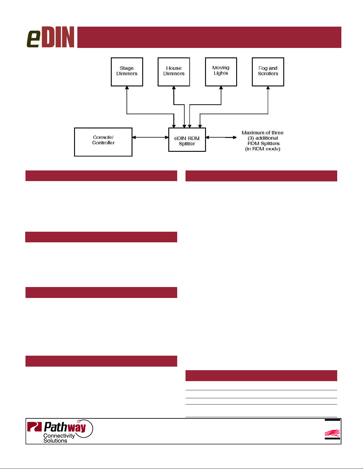
Typical System Layout
DMX TERMINATION
The eDIN DMX/RDM Splitter is internally terminated, to
comply with the RDM standard, and does not require
the user to provide any further termination.
The DMX THRU connector, as well as each
output leg, begins a new DMX output run that requires
termination at the other end. Proper termination is a
120 Ω resistor between pins 2 and 3 (D– and D+)
DMX THRU CONNECTOR
The DMX Thru connector is an active pass through and
fully supports RDM. Due to timing restrictions in the
RDM standard, no more than four (4) eDIN DMX/RDM
Splitters may be daisy-chained together in one run. If
RDM is disabled on all cards, up to eight (8) modules
may be daisy-chained
RDM ENABLE/DISABLE
Some legacy DMX equipment does not check the start
code of data packets on the network and may treat
RDM data as if it were DMX levels. When the RDM
switch is in the ‘disable’ position, the eDIN DMX/RDM
Splitter will filter out all RDM packets, preventing downstream legacy equipment from acting unpredictably.
The module should have the power cycled whenever
the RDM switch is returned to the ‘enable’ position.
RDM RESPONDER FEATURES
The eDIN DMX/RDM Splitter is fully compliant with
ANSI E1.20 as a responder device. An RDM controller,
such as the Pathway DMX Repeater Pro will discover
and retrieve the module’s unique identifier (UID) and its
firmware version. The module is fully discoverable and
configurable even with the RDM switch in the ‘disable’
position.
Pathway Connectivity Inc
103-1439 17Avenue SE Calgary AB Canada T2G 1J9
tel (403) 243-8110 fax (403) 287-1281
E1.20 REMOTE DEVICE MANAGEMENT
ANSI E1.20 Remote Device Management (RDM) is an
open standard data protocol that provides DMX512-A
networks with the option of fully bi-directional communications (aka ’talkback’). By using half-duplex data communications, RDM operates over the same wire pair
(pins 2 and 3) as DMX, ensuring backwards compatibility with all DMX installations.
RDM devices are classified as ‘controllers’ or
‘responders’. Only one controller may be active on a
given network. When the controller issues a command,
it listens for a response within a prescribed time. During
this period, opto-splitters like the eDIN DMX/RDM Splitter must be prepared to pass data back to the controller.
RDM data packets differ from DMX data packets by using a different start code. The eDIN DMX/RDM
Splitter detects this different start code and uses it as a
cue to change data direction. Because of the processing involved in changing direction, the RDM standard
specifies a maximum of four (4) splitters between the
controller and the last responding device. This limit
does not apply to systems with RDM disabled.
Individual ‘responder’ devices should not be
installed between the eDIN DMX/RDM Splitter and the
controller. RDM ‘responders’ should only be installed
downstream of the eDIN DMX/RDM Splitter.
The RDM standard does not currently support a
method of firmware upgrade for responders.
SPECIFICATIONS
P
OWER SUPPLY
I
NPUT SIGNAL
O
UTPUTS
C
ONNECTIONS
S
IZE
:
: 9-30 VDC, 6W
: ANSI E1.11 DMX512-A, ANSI E1.20 RDM
: ANSI E1.11 DMX512-A, ANSI E1.20 RDM
Two piece compression screw terminals, 16 - 24 AWG
:
3.5” x 6.25” x 1.25” (90mm x 160mm x 35mm)
support@pathwayconnect.com
www.pathwayconnect.com
rev.1 v1
Printed in Canada
3/09
 Loading...