

Page 1
Model 1008 LED Dimmer
OVERVIEW
The Pathway eDIN LED Dimmer/DC Driver provides
DMX512 control over LEDs and other DC devices.
Each module provides 6 channels of control.
When controlling LEDs, the module acts as a
dimming interface only. The LED fixture will require a
separate regulated DC power supply, as
recommended by its manufacturer.
These instructions apply to REV 2 modules.
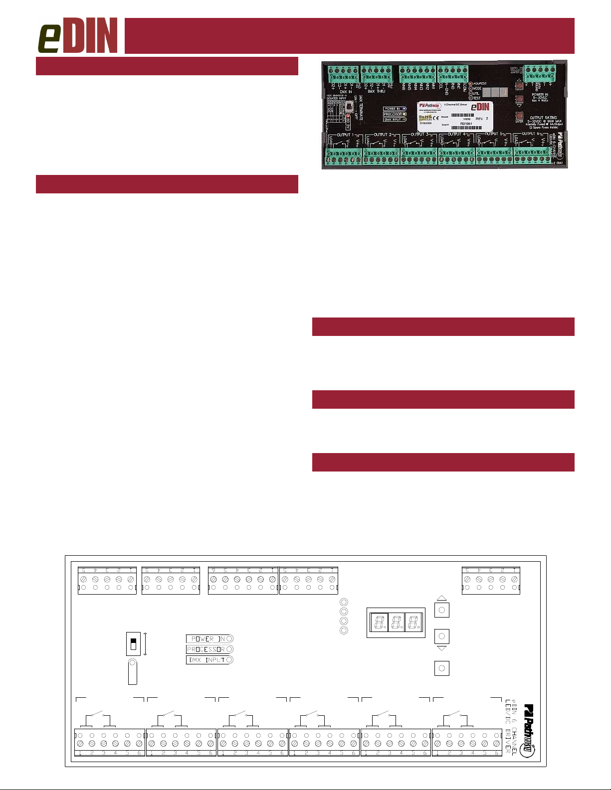
CONNECTIONS
eDIN LED Dimmer/DC Driver modules feature terminal
strips that can be removed from the module to facilitate
wiring and replacement. Make the following connections
WITH THE POWER TURNED OFF:
POWER
The module is designed to run on a range of voltages
from 9 to 30 VDC, at 500mA per card connected.
Observe the correct polarity when connecting to V+
and V-. A second set of terminals is provided on the
same connector to daisy-chain power to other eDIN modules. Earth Ground must be connected to the enclosure’s
chassis or ground terminal to ensure EMC compliance.
DMX512
DMX connections consist of a shield wire and one or
two data pairs. DMX IN is wired from the control console,
or other source. DMX THRU may be daisy-chained to the
DMX IN of other eDIN cards, or to other DMX equipment.
Connect DATA+ and DATA– wires to D1+ and D1respectively. The optional data pair may be connected to
D2+ and D2-. Observe the same polarity convention
throughout the system. Connect the shield wire to the
SHLD/COM terminal.
DC/PWM OUTPUTS
The LED Dimmer/DC Driver interface provides six (6)
outputs that will each handle up to 4 amps at voltages up
to 30VDC. The outputs are of the current-sinking type. A
separate DC power supply is required, appropriately sized
for the connected load, as recommended by the connected equipment’s manufacturer.
REV 2
Manual
Each output is fully opto-isolated from the other outputs, from the DMX signal and from the eDIN board
power supply. Multiple pins are provided to allow for load
spreading. Outputs are connected as follows:
LOAD- (Terminals 1 & 2): Connects to the negative terminal of the load, or the LED Cathode.
V- (Terminals 3 & 4): Connects to the negative or common terminal of the load power supply.
V+ (Terminals 5 & 6): Connects to the positive terminal of
the load power supply and to the positive terminal of the
load, or the LED Anode.
‘DMX PRESENT’ RELAY CLOSURE
Wire RCOM to RNC or RNO for a normally closed or
normally open DMX indicator, as desired.
When DMX is present, the closure will be held in a
state opposite to its ‘normal’ position.
CONTACT CLOSURE ‘PANIC’ INPUT
When CCL is shorted to IN-GND, for example by closing an e-stop switch, all outputs are forced to the MAX
output level, regardless of DMX level or signal presence.
ANALOG INPUT
Applying a 0-10VDC input between any AIN(x)
and the IN-GND pin will drive that particular output. Output level is an HTP-merge between the DC voltage level
and the incoming DMX signal for that channel.
Do not exceed 10VDC maximum input voltage.
D2+
LOAD-
D2-
D1-
D1+
DMX IN
OUTPUT 1
V-
IN
V+
IN
SHLDONCOM
ISO 5V
V+
IN
D2+
D2-
DMX THRU
DMX
TERMINATE
OFF
LOAD-
D1+
D1-
OUTPUT 2
V-
IN
COM
SHLD
AIN6
V+INV+
IN
AIN5
LOAD-
AIN3
AIN4
OUTPUT 3
CCL
AIN1
AIN2
V+INV+
V-
IN
IN
IN-GND
LOAD-
RNC
RNO
RCOM
OUTPUT 4
V-
IN
IN
ADDRESS
MODE
UTIL
TEST
LOAD-
V+INV+
OUTPUT 5
V-
IN
GROUND
V+
OUTPUT RATING
ENTER
LOAD-
V+INV+
IN
Internally Fused @ 4A/Output
OUTPUT 6
V-
IN
V-
V-
EARTH
POWER IN
9-30VDC
Max 4 Watts
5-30vdc @ 96w MAX
(2 Spare Fuses Inside)
V+INV+
IN
V+
Page 2
LED Dimmer/DC Driver Configuration
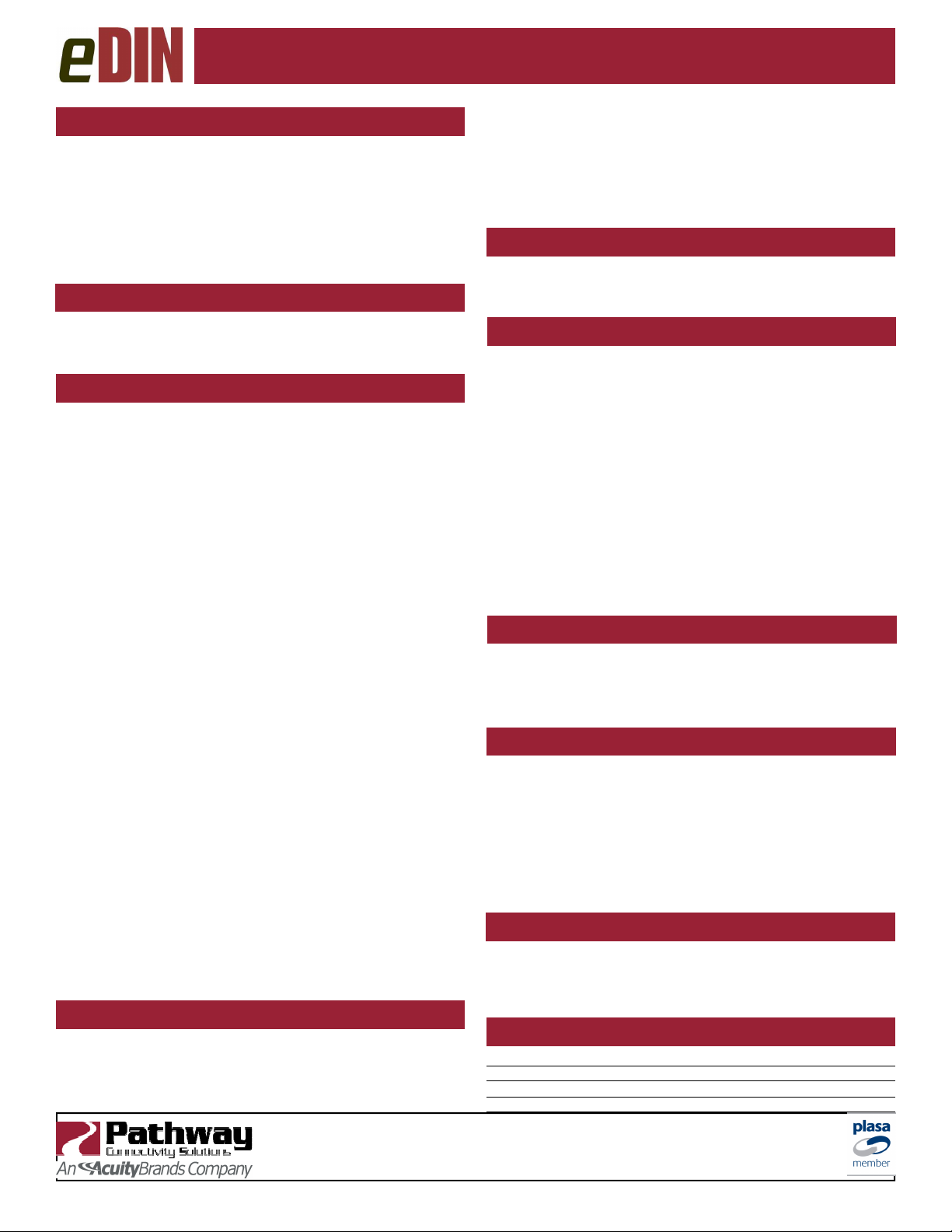
CONFIGURATION
The eDIN user interface has 2 operating modes: Function
and Edit. Press the ▲ or ▼ buttons to select a function,
as indicated by the LEDs next to ADDRESS, MODE,
UTIL, and TEST. Once selected, press and hold the
ENTER button until a dot appears in the lower right-hand
corner of the display. The card is now in EDIT mode.
Use the ▲ or ▼ buttons to change, then press ENTER to
accept the new value.
SET DMX ADDRESS
Once in ADDRESS edit mode, press ▲ or ▼ to change
the start address to the desired value between 1 and 512.
Press ENTER to save the new start address.
SET OPERATING MODE
Mode 1: Default LED Control Mode
(6 channels)
The incoming DMX channel level is interpolated to produce a 16-bit value. A weighted fade curve is also applied
to compensate for LED response, producing an apparently linear fade to the human eye.
Mode 2: DMX Double Precision Mode with Curve
(12 channels)
Two DMX control channels are used to produce a 16-bit
value for each output. A weighted curve is also applied .
Mode 3: DMX Double Precision Mode without Curve
(12 channels)
Two DMX control channels are used to produce a 16-bit
value for each output with no compensating curve. Output
follows the DMX values linearly.
Mode 4: Non-Dim Mode
When the DMX channel is below 50%, the corresponding
output will be off. When the channel level is above 50%,
the corresponding output will be on (full). Use for nondimming loads such as solid state relays or solenoid coils.
Mode 5: Single channel control
One DMX channel, the start address, controls all six outputs from the module.
Mode 6: 3 Channel Mirror Mode with Curve
(3 channels)
Outputs are paired (1/4, 2/5, 3/6). Paired outputs are
driven by the same DMX channel, with the weighted
curve applied to the output.
Mode 7: 3 Channel Mirror Mode without Curve
(3 channels)
Outputs are paired (1/4, 2/5, 3/6). Paired outputs are
driven by the same DMX channel, with no compensating
curve. Output follows the DMX values linearly..
UTIL MODE
There are four UTIL modes.
A: Adjusts the smoothing algorithm between 1 (very
smooth) to 100 (no smoothing). Factory default is 64.
B: Adjusts a Grand Master maximum output level be-
Pathway Connectivity
103—1439 17Avenue SE Calgary AB Canada T2G 1J9
tel (403) 243-8110 fax (403) 287-1281
tween 0 (off) and 256 (default).
C: Sets a MIN output level between 0 and 255, that the
card will always output even in the absence of DMX.
D: Sets DMX signal loss behavior. Options are “0” - zero
seconds, “0.5” - thirty seconds, “1” - one minute, “5” five minutes and “--” forever (default).
TEST MODE
Use ▲ or ▼ to cycle the display from 1 through 6. The
corresponding output will be at full. Normal DMX input
will be ignored. Press ENTER to exit test mode.
STATUS INDICATORS
POWER IN Blue. Steady glow indicates power
supply OK; off indicates no power.
PROCESSOR Green. Steady glow indicates processor
is OK; off when POWER IN is lit indicates processor failure.
DMX INPUT Amber. Steady glow indicates data sig-
nal received; off indicates no data signal.
MENU
FUNCTION
ISO INPUT Red. Steady glow indicates isolated 5V
OUTPUT Amber. Glow approximates output level.
Amber. Indicates which function is active on the numeric display.
supply is OK. Off indicates no power.
DMX TERMINATE
DMX rules require the final device in-line have a terminating resistor. If there are other devices connected to
the DMX THRU terminals, the DMX TERMINATE switch
should be OFF. Otherwise the terminator should be ON.
RDM RESPONDER FEATURES
The eDIN 1008 LED Dimmer module is fully compliant
with ANSI E1.20 Remote Device Management as a responder device. An RDM controller can discover and
retrieve the card’s DMX start address, firmware version
and operating mode (personality). DMX start address
and operating mode are remotely configurable by the controller. Starting with firmware 1.5.5, an RDM utility can
upgrade the firmware in the field.
COMMENTARY ON DIMMING LEDS
The #1008 eDIN LED Dimmer does not regulate the
current supplied to the LED. Always use a currentregulated power supply, approved by the LED manufacturer, to supply the LED fixture.
SPECIFICATIONS
Power Supply: 9-30VDC, 500mA
Input Signal: USITT DMX512A, ANSI E 1.20 RDM
Data Connections: Pluggable screw-down connector, AWG 24 to 14
Output Rating 4A at 30VDC maximum each
support@pathwayconnect.com
www.pathwayconnect.com
rev.3, ver.2
Printed in Canada
3/12
 Loading...