

Page 1
Model 1007 Merger Manual
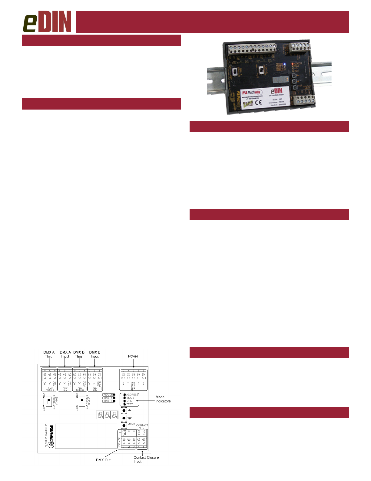
OVERVIEW
Pathway eDIN Mergers combine two DMX
streams in a number of different ways,
depending on your application. The DIN form
factor makes installation fast and easy.
Modules may be cascaded together, up to
four levels deep.
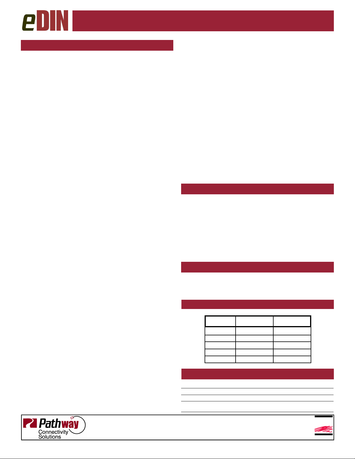
CONNECTIONS
eDIN Mergers feature terminal strips that can be removed
from the module to facilitate wiring. Make the following
connections, WITH THE POWER TURNED OFF:
POWER
The module will run on a range from 9 to 30 VDC at
500mA per card connected. Observe the correct polarity
when connecting to the V+ and V-. A second set of terminals are provided on the connector to daisy-chain power
to other eDIN modules. A grounding terminal is also provided for connection to earth ground.
DMX
DMX connections consist of a shield and one or two data
pairs. The two DMX IN usually come from control consoles, architectural controllers or opto-splitters. DMX
THRU pins on each connector may be daisy-chained to
the DMX IN of other eDIN modules or other DMX equipment. DMX OUT sends the merged signal and is connected to the DMX inputs of the appropriate downstream
devices.
Connect the DATA+ and DATA– wires to D1+ and D1respectively for each of DMX A, DMX B and DMX OUT.
Observe the same polarity convention throughout the system. Connect the cable shield to the SHLD COM terminal.
A DMX reference chart is provided on the next page.
CONTACT INPUT
Pins 4 and 5, on the same terminal strip as the DMX OUT
pins, may be connected to an external contact closure.
Closing the contact (shorting pins 4 and 5) forces a switch
from DMX A to DMX B in operating modes 7 & 8.
STATUS INDICATORS
POWER
DMX A
DMX B
Blue. Glowing steadily indicates power
supply OK; off indicates no power.
Amber. Glowing steadily indicates DMX is
present on DMX input A; off indicates no
incoming DMX
Amber. Glowing steadily indicates DMX is
present on DMX input B; off indicates no
incoming DMX
CONFIGURATION
The user interface has 2 operating modes: Function and
Edit. Press the ▲ or ▼ buttons to cycle through the
available functions: ADDRESS, MODE, UTIL, and TEST.
When the LED beside the desired function is lit, press
and hold the ENTER button until a dot appears at the bottom right of the numeric display. The card is now in EDIT
mode.
ADDRESS sets the DMX offset start-address for
modes requiring one. MODE sets the operating mode.
UTIL is reserved for future use. TEST toggles each output
channel on or off.
When done editing a parameter, press the ENTER
button again. The dot will disappear, the parameter will
be saved, and the card will be ready for operation.
Hint: You can press and hold the ▲ or ▼ buttons to
speed through values.
SET DMX ADDRESS OFFSET
Once in ADDRESS edit mode, press ▲ or ▼ to change
the DMX offset start-address to the desired value.
Press enter to save the new value.
DMX offset start-address is applied to the DMX B
input only, and its effect is dependent on the operating
mode of the module.
TEST MODE
Once in TEST mode, press ▲ or ▼ to cycle the display
from 1 to 512. The corresponding channel will cut to full
and hold. Press ENTER to exit test mode.
While in test mode, normal DMX input will be ignored
and only the test channel will be active.
Page 2
ESTA
ENTERTAINMENT SERVICES &
TECHNOLOGY ASSOCIATION
Merger Configuration
SET OPERATING MODE
Once in MODE edit, use ▲ or ▼ to choose from:
Mode 1: HTP Merge with 2 second status quo
DMX A and DMX B are merged using a highest-takesprecedence comparison, on a channel-by-channel basis.
If DMX A channel 5 is at 10% and DMX B channel 5 is at
50%, the DMX output for channel 5 will be 50%. DMX B
input will start at the channel number set by DMX address
offset. If all DMX input is lost, the last DMX look is maintained for two seconds then stops.
Mode 2: HTP Merge with 5 minute status quo
DMX A and DMX B are merged using a highest-takesprecedence comparison, on a channel-by-channel basis.
DMX B input will start at the channel number set by DMX
address offset. If all DMX input is lost, the last DMX look
is maintained for five minutes then stops.
Mode 3: HTP Merge with offset and 2 sec status quo
Input channels below the DMX address offset on DMX B
will be ignored. Channels above and including the offset
will be merged with their respective input channels on
DMX A using a highest-takes-precedence comparison, on
a channel-by-channel basis. If all DMX input is lost, the
last DMX look is maintained for two seconds then stops.
Mode 4: HTP Merge with offset and 5 min status quo
Input channels below the DMX address offset on DMX B
will be ignored. Channels above and including the offset
will be merged with their respective input channels on
DMX A using a highest-takes-precedence comparison, on
a channel-by-channel basis. If all DMX input is lost, the
last DMX look is maintained for five minutes then stops.
Mode 5: Auto Backup with 2 second status quo
DMX B is ignored as long as signal is present on DMX A.
If DMX A is lost, the output will immediately switch to
DMX B. If DMX A returns, output will immediately switch
back. If all DMX input is lost, the last DMX look is maintained for two seconds then stops.
Mode 6: Auto Backup with 5 minutes status quo
DMX B is ignored as long as signal is present on DMX A.
If DMX A is lost, the output will immediately switch to
DMX B. If DMX A returns, output will immediately switch
back. If all DMX input is lost, the last DMX look is maintained for five minutes then stops.
Mode 7: External Backup using a switch, 2 second
status quo. DMX B is ignored until the contact closure
input is closed (pins 4 and 5 on the DMX OUT shorted).
When the contact input is opened, DMX A is immediately
restored. Output source is controlled solely by the switch,
not loss of signal. If all DMX input is lost, the last DMX
look is maintained for two seconds then stops.
Mode 8: External Backup using a switch, 5 minute
status quo. DMX B is ignored until the contact closure
input is closed (pins 4 and 5 on the DMX OUT shorted).
When the contact input is opened, DMX A is immediately
restored. Output source is controlled solely by the switch,
not loss of signal. If all DMX input is lost, the last DMX
look is maintained for two seconds then stops.
Mode 9: Append with 2 second status quo
DMX B is appended to DMX A beginning at the DMX address offset. The appended channels are not merged. If
DMX input is lost, the last DMX look is maintained for two
seconds then stops. Ideal for consoles in different rooms
accessing separate ranges of the same dimmer rack.
Mode 10: Append with 5 minute status quo
DMX B is appended to DMX A beginning at the DMX address offset. The appended channels are not merged. If
DMX input is lost, the last DMX look is maintained for five
minutes then stops. Ideal for consoles in different rooms
accessing separate ranges of the same dimmer rack.
Mode 11: Test Mode with channel fade
Similar to TEST mode, only the selected channel fades
up and down. The default channel is the set by the DMX
address offset. If TEST is entered while in this mode, the
active channel can be selected using ▲ or ▼. DMX A
and B inputs are ignored while in this mode.
Modes 12 –15: Reserved for future use
DMX TERMINATE
The rules of DMX require the last device on a DMX line
be terminated with a 120Ω resistor between pins 2 and 3
to prevent signal reflection. The Merger module has termination switches for both DMX A and DMX B. If there is
no connection to the DMX THRU terminals, the DMX Terminate switch for that input should be ON. If there are
other devices connected to the DMX THRU terminals, the
DMX Terminate switch should be OFF and termination be
applied to the final device in the daisy-chain.
REMOTE DEVICE MANAGEMENT
The #1007 eDIN Merger is not compatible with the E1.20
Remote Device Management (RDM) protocol. The RDM
standard has no provision for signal merging at this time.
DMX REFERENCE
DMX
DMX XLR5
DMXDMX
Common 1
Data - 2 D1-
Data + 3 D1+
unused 4 N/A
unused 5 N/A
XLR5 pin
pin eDIN terminal
XLR5XLR5
pin pin
eDIN terminal
eDIN terminaleDIN terminal
SHLD /COM
SPECIFICATIONS
POWER SUPPLY: 9-30VDC, 500mA
INPUT SIGNAL: USITT DMX512A
OUTPUT SIGNAL: USITT DMX512A
CONNECTIONS: Two piece compression screw terminals
Accepts AWG 24 to 14, stranded or solid
rev.2, ver.1
Pathway Connectivity Solutions
#103—1439 17Avenue SE Calgary AB, Canada T2G 1J9
tel (403) 243-8110 fax (403) 287-1281
support@pathwayconnect.com
www.pathwayconnect.com
Printed in Canada
2/09
 Loading...