

Page 1
Model 1004 16-Channel
TM
DMX IN FROM
MENU FUNCTION
Demultiplexer
OVERVIEW
The 1004 eDIN demultiplexer converts DMX512 signals into
16 channels of analog control voltage. The demultiplexer
can also control Mark7-type uorescent ballasts, solid state
relays or LEDs.
The module is RDM discoverable and congurable.
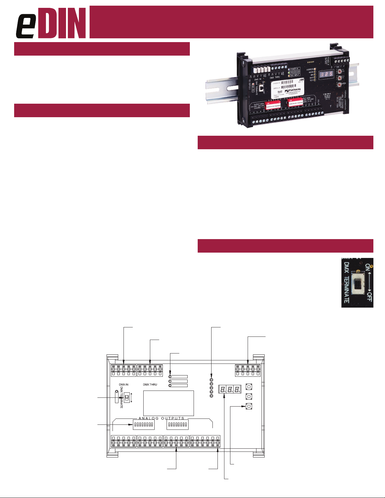
CONNECTIONS
The 1004 features terminal strips that can be removed from the
card to facilitate easy wiring installation or replacement. Make the
following connections, WITH THE POWER TURNED OFF.
POWER
The module will run on a range from 9 to 30 VDC at a maximum
of 6 Watts. Observe the correct polarity when connecting the V+
and V-. A second set of terminals are provided on the connector to
daisy-chain power to other eDIN modules. The EARTH GROUND
terminal must be connected to the enclosure’s chassis or electrical
ground terminal to ensure EMC compliance.
DMX512
DMX connections consist of a shield and data pair. Connect the
DATA+ and DATA- wires to D1+ and D1- respectively for each of
DMX IN and DMX THRU. Observe the same polarity convention
throughout the system. Connect the cable shield to the SHLD COM
terminal.
DMX THRU may be daisy-chained to the DMX IN of other eDIN
modules.
ANALOG OUTPUTS
Sixteen analog output terminals are provided in groups of four,
each with a common terminal. All common terminals are internally
connected, so only one needs to be tied to the device being
controlled.
Outputs are rated up to 15 VDC, 10mA per channel, sourcing; or
30mA per channel, sinking. Maximum wire run is 150 meters (500 ft).
Manual
STATUS INDICATORS
POWER IN Blue. Steady glow indicates power supply OK;
o indicates no power.
PROCESSOR Green. Steady glow indicates processor is OK;
o when POWER IN is lit indicates processor
failure.
DMX INPUT Amber. Steady glow indicates port latched
to active DMX source; o indicates no signal
present.
FUNCTION Amber. Indicates the function associated with
the numeric display.
DMX TERMINATE
DMX rules require the last device on a DMX line to be
terminated with a 120Ω resistor between pins 2 and 3
to prevent signal reection. If there is no connection to
the DMX THRU terminals, the DMX Terminate switch
should be ON.
If there are other devices connected to the DMX
THRU terminal, the DMX Terminate switch should be
OFF and termination be applied to the nal device in the daisy-chain.
END OF LINE
TERMINATION SWITCH
DIODE SHUNT SWITCHES
ON=SOURCE MODE
OFF=SINKING MODE
(REV 5 AND HIGHER ONLY)
NCNCD1+
1
CONTROL SYSTEM
DMX THRU TO
OTHER eDIN MODULES
NCNCD1+
COM
SHLD
D1-
ON OFF
ISO 5V
DIODE SHUNT CH 1-8 DIODE SHUNT CH 9-16
COM
5
432
16 ANALOG OUTPUTS
10mA SOURCE / 30mA SINK
@ 15VDC MAX
COM
SHLD
D1-
COM
876
9
POWER IN
PROCESSOR
DMX INPUT
11
10
STATUS LEDs
ADDRESS
MODE
COM
15
14
13
12
PANIC MODE
DRY CONTACT
INPUT
1004-200-REV1 04/18/19
TEST
LEDs
POWER IN
6 W MAX
9-30VDC
V+
V-V+V-
EARTH
GND
MIN
MAX
CCL-IN
COM
16
LED NUMERIC
DISPLAY
CONVERTER
PROGRAM
PUSHBUTTONS
POWER IN:
9-30VDC, 6W SUPPLY REQUIRED
USE #1001-100-24-DIN POWER SUPPLY
OR EQUAL.
CONNECT EARTH GROUND TO PROTECT
DMX INPUT FROM RF INTERFERENCE
CARRIED ON CABLE SHIELD.
ENTER
Pathway Connectivity
eDIN 16 CHANNEL
DMX-ANALOG
Page 2

Model 1004 16-Channel
TM
Demultiplexer
Manual
CONFIGURATION
To congure, rst press the ▲ or ▼ buttons to select the
desired function, indicated by the LED next to ADDRESS,
MODE, MIN, MAX, or TEST. Once selected, press and
hold the ENTER button until a dot appears in the lower
right-hand corner of the display. The card is now in EDIT
mode.
When done editing a parameter, press ENTER. The dot will
disappear, the new value will be saved and the unit will be ready
for operation.
SET DMX ADDRESS
One in ADDRESS edit mode, press ▲ or ▼ to change the start
address to the desired value. Press ENTER to save the address.
Valid addresses range from 1 to 512.
SET OPERATING MODE
Once in MODE edit, choose from the following:
• MODE 1: 0-10VDC Output (MAX will read 158)
• MODE 2: 0-5VDC Output (MAX will read 79)
• MODE 3: 0-15VDC Output (MAX will read 237)
• MODE 4: 0-2.5VDC Output (MAX will read 40)
• MODE 5: Custom D-to-A (set your own voltage)
• MODE 6: EFBC/LED Control - 10% threshold
• MODE 7: Non-Dim (see below)
• MODE 8: EFBC/LED Control - 1% threshold
SET MIN AND MAX VOLTAGE OUTPUT LEVELS
To set a custom output voltage, conrm the DMX start address is set
to 1. Connect a voltmeter between output 1 and COM on the card.
Connect a DMX source to DMX IN. Using your source, vary the DMX
level on channel 1 and conrm that the voltage output is changing.
Set the DMX level to full.
Use the ▲ or ▼ buttons and ENTER to select MAX for editing.
Use ▲ or ▼ while observing the output on the voltmeter. Once the
voltage is at the level you desire, press ENTER to save. Repeat this
process to set a MIN level. Valid MIN levels are between 0 and 254.
Valid MAX levels are between 1 and 255. 255 roughly corresponds
to an output of 16VDC. Customizing these values will place the card
in Mode 5. MIN and MAX should be checked in Modes 6, 7 and 8,
with MAX set as a value of 158 to ensure proper operation of
the solid state relays.
NON-DIM CONTROL
Mode 7 provides non-dim control of solid state relays or LEDs. At a
DMX level of 0%, each channel outputs +10VDC. The output voltage
drops to zero when DMX passes 50%. All blocking diodes must be
shunted (bypassed) in this mode.
EFBC / LED CONTROL
Mode 6 and 8 allow unied control of up to eight circuits of LED
xtures or Mark 7-type electronic uorescent ballasts, with a
maximum of 20 xtures/ballasts on each circuit. Two channels are
used for each circuit. Channels are paired: 1 with 9, 2 with 10, and
so on.
The lower channel provides 0-10VDC dimming control, while the
higher acts as a non-dim, when connected to a solid state relay
controlling the circuit’s AC supply. In mode 6, the non-dim triggers
when DMX passes through 10%. In mode 8, the non-dim threshold
is 1%. All blocking diodes must be shunted (bypassed) in this mode.
TEST MODE
Once in TEST mode, using the ▲ or ▼ buttons will toggle each
output on and o. The output number is shown on the right hand
display. DMX input is ignored while in TEST mode.
CCL PIN (PANIC INPUT)
Shorting the CCL pin to COM will drive all outputs to full.
The CCL input overrides the DMX input level.
SELF-TEST
Press the ▲ button while turning power on to enter self-test mode.
All LEDs will ash sequentially. The display will cycle 0 through 9,
then show the serial number and rmware version. Cycle power to
end self-test.
DIODE SHUNTS
The behavior of the diode shunts is dependent on the module’s
revision level .The revision number is shown on the product label,
next to the part number.
The diodes prevent the control signal from back-feeding into the
output and damaging the module. The diodes must removed from
the circuit to allow sinking control. The 16 DIP switches are wired
as shunts, allowing the diodes to be engaged or disengaged outputby-output.
REV 4 and below: The blocking diodes are engaged by default. With
the shunt switches in the “o” position, the diodes will prevent current
backow. This is the correct arrangement for driving analog dimmers.
With the shunts in the “on” position, the diodes are bypassed. This
is the correct arrangement for sinking control of EFBCs and LED
dimmers.
REV 5 and above: The blocking diodes are bypassed by default.
With the DIP switches in the “o” position, current will backow
through the card. This is the correct arrangement to allow sinking
control of EFBCs and LED dimmers. With the DIP switches in the
“on” position, the diodes will block backow current. This is the
correct arrangement for driving analog dimmers.
Pathway Connectivity Solutions
1004-200-REV1 04/18/19
#103—1439 17Avenue SE Calgary AB
Canada T2G 1J9
support@pathwayconnect.com
www.pathwayconnect.com
tel (403) 243-8110 fax (403) 287-1281
Page 3

Model 1004 16-Channel
TM
Demultiplexer
Manual
E1.20 RDM RESPONDER FEATURES
The 1004 is fully compliant with ANSI E1.20 Remote Device
Management as a responder device. An RDM Controller can
discover and set the card’s DMX start address, rmware version and
operating mode. With Pathscape software, the user can upgrade the
rmware in the eld.
USE WITH NON-ISOLATED LED DRIVERS
The 1004 is not intended for use with non-isolated LED drivers.
See the next page for a technical bulletin with details.
ELECTRICAL INFORMATION
• Power input: 9-30VDC, 6W maximum
• 250V Fault protection on DMX input
• 1500V Opto-isolation between DMX input and analog
outputs
• Connections (DMX):
• Compression Fit (Screw Terminal): stranded, 14-30 AWG
• IDC Connector: Cat5/6 or solid wire, 22-24 AWG
• Input Signal: ANSI E1.11 DMX512-A, ANSI E1.20 RDM
• Outputs: 16 analog 0-10VDC nominal, maximum 16VDC
• Output rating: 10mA current drive per channel (sourcing)
or 30mA per channel (sinking), diode isolated
Exceeding this rating may result damage to the device.
PHYISCAL
• 0.7 lbs (0.316 kg)
• 6.25”W x 4”H x 1.55”D (159mm x 103mm x 40mm)
COMPLIANCE
• ANSI E1.11 DMX512-A(2008)/USITT DMX512(1990)
• ANSI E1.20 RDM(2010) - Remote Device Management
• ANSI E1.3 0-10V Analog Control (with diode shunts on)
• ANSI C82.11 Fluorescent Ballast Control (diode shunts o)
• RoHS 2011/65/EU
• CE
Pathway Connectivity Solutions
1004-200-REV1 04/18/19
#103—1439 17Avenue SE Calgary AB
Canada T2G 1J9
support@pathwayconnect.com
www.pathwayconnect.com
tel (403) 243-8110 fax (403) 287-1281
Page 4

TECHNICAL BULLETIN #14_09_4-1
Product: eDIN #1004 - Demultiplexer
Subject: 0-10V Dimming of Non-Isolated LED Drivers
Scope: Applies to all model revisions
OVERVIEW
Use of the eDIN #1004 Demultiplexer with non-isolated LED fixture drivers is not recommended.
The eDIN #1004 16-channel Demultiplexer is designed to provide sinking control of LED fixture
drivers that have a secondary Class 2 dimming circuit that is isolated from the mains power
input. Connection of the Demultiplexer to non-isolated drivers, or drivers with Class 1 rated
dimming circuits, will cause damage to the Demultiplexer.
This damage is considered non-warranty for the purpose of repair and replacement.
DETAILS
Pathway has determined that one or more LED luminaire manufacturers are now providing non-isolated
fixture drivers with non-Class 2, 0-10V volt dimming option. The lack of isolation between the mains
power leads and the low voltage wiring in the drivers results in transient voltages on the low voltage
control leads. The transient voltages may be as high as or higher than 120V.
In compliance with ANSI C82.11c Low Voltage Control Interfaces for Controllable Ballasts, the #1004
Demultiplexer will accept voltages between -15V and +15V with no damage. Application of voltages
outside this range to any of the analog outputs may result in damage to all outputs on the Demultiplexer.
Damage will result in reduced dimming range or loss of dimming capability altogether.
The damage caused by this misapplication of the product is readily determined when Demultiplexers are
returned for repair. Repairs to Demultiplexers deemed to be damaged by connection to non-isolated
LED fixture drivers will only be performed on a non-warranty basis, and all non-warranty repair fees and
policies will apply.
EXAMPLE
A popular choice for 0-10V control of dimmable LED fixtures is the Philips Xitanium product line. Care
must be taken to choose the fully isolated version of these drivers. Isolated Xitanium drivers are typically
identified by the letters “DO” at the end of the model number. Non-isolated Xitanium drivers are typically
identified by the letters “DN” or “DL” at the end of the model number. It is the responsibility of the
installer to determine the compatibility of the fixture driver and the #1004 Demultiplexer.
Pathway Connectivity
Acuity Brands Lighting Canada Inc.
103 - 1439 17th Avenue SE
Calgary AB Canada T2G 1J9
403 243 8110 fax 403 287 1281
www.pathwayconnect.com
 Loading...