

Page 1
Model 1003 Contact Closure Manual
OVERVIEW
Pathway eDIN Contact Closure outputs provide
DMX-controlled form-C relay switch closures for
both power and signal level switching. The card
is RDM discoverable and configurable. The DIN
form factor makes installation fast and easy.
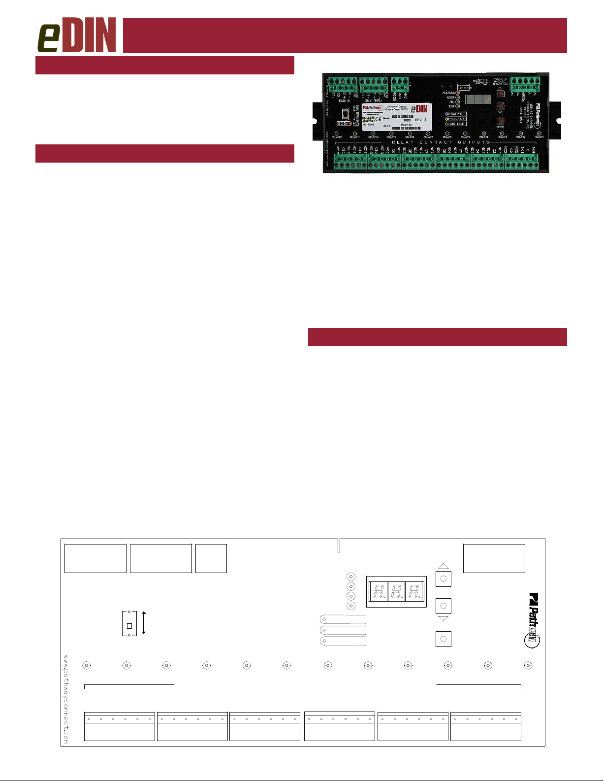
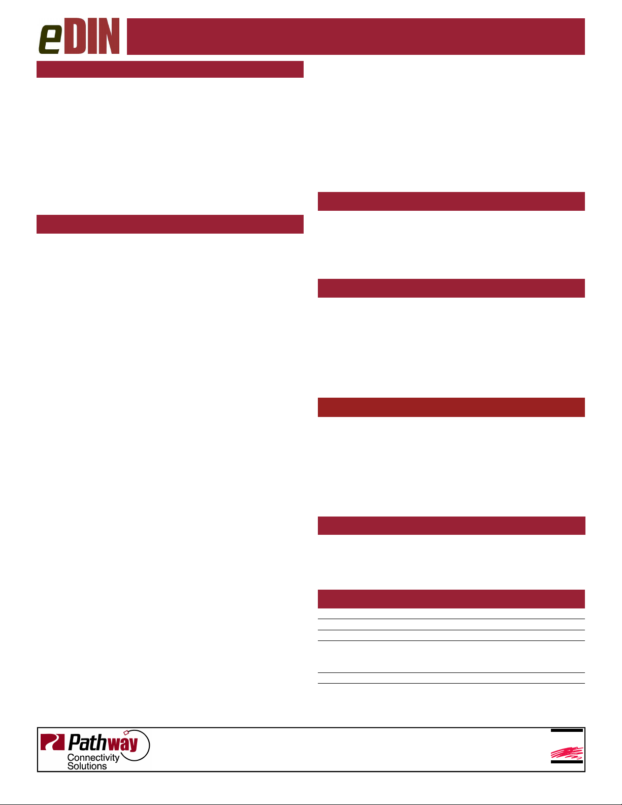
CONNECTIONS
eDIN Contact Closures Interfaces feature terminal strips
that can be removed from the card to facilitate easy wire
installation or replacement. Make the following connections, WITH THE POWER TURNED OFF:
POWER
This interface is designed to run on a range of voltages
from 9-30 volts DC. Each module requires 400mA.
Observe the correct polarity when connecting to V+ and
V-. A second set of terminals are provided to connect to
other eDIN modules. The EARTH GROUND terminal
must be connected to the enclosure’s chassis or electrical
ground terminal to ensure EMC compliance.
DMX
DMX connections consist of a shield and a data pair. A
optional second auxiliary data pair is also occasionally
employed. DMX IN usually comes from a control console,
architectural controller or opto-splitter. DMX THRU provides a means to daisy-chain DMX to other eDIN modules. Connect DATA+ and DATA-, to D1+ and D1-. Observe the same polarity convention throughout the system. Connect the cable shield or common to the SHLD
COM terminal.
DMX PRESENT RELAY CLOSURE
Starting with firmware 1.5.5, the J13 DMX present relay
closure is supported. Wire RCOM to RNO or RNC for
normally open or normally closed, as desired.
CONTACT OUTPUTS
The eDIN contact closure interface can be thought of as
twelve DMX controllable switch closures. As switches,
they need two connections each since the switches provide no voltage or current on their own. One connection is
to the supply and one goes to the load. The switch closures are provided by twelve relays. Each relay has three
sets of contacts; normally open (NO), normally closed
(NC) and common (C). Generally the normally open contacts are what are used, providing an open switch that
closes when the relay is energized. Normally closed contacts operate in the opposite manner, providing a closed
switch that opens when the relay is energized.
All common terminals are independent of one another.
STATUS INDICATORS
POWER IN Blue. Glowing steadily indicates power
supply OK; off indicates no power.
PROCESSOR Green. Glowing steadily indicates proces-
sor is OK; off when POWER IN is lit indicates processor failure.
DMX
INPUT
RELAY Red. Glowing steadily indicates relay is
FUNCTION Amber. Indicates the function associated
Amber. Glowing steadily indicates data
signal received; off indicates no signal
present.
energized. Flickers for momentary action.
with the numeric display.
DMX IN
NC12
DMX
DMX THRU
ON
TERMINATEDMX
OFF
NC10
NO11
NC11
NO12
C12
C11
PRESENT
RELAY
ADDRESS
MODE
UTIL
TEST
POWER IN
PROCESSOR
DMX INPUT
RELAY6 RELAY1RELAY2
NO10
C10
R E L A Y C O N T A C T O U T P U T S
NC6
NO7
NC7
NO8
NC8
NO9
NC9
C9
C8
C7
C6
RELAY5
NO5
NC5
NO6
C5
RELAY4RELAY7RELAY8RELAY9RELAY10RELAY11RELAY12
NO4
NC4
C4
ENTER
RELAY3
NO3
NC3
C3
POWER IN
CONTACT CLOSURE
eDIN 12 CHANNEL
OUTPUT
Rev.4
NO2
NC2
NC1
C2
NO1
C1
Page 2
ESTA
ENTERTAINMENT SERVICES &
T
ECHNOLOGY ASSOCIATION
Contact Closure Configuration
CONFIGURATION
The eDIN user interface has 2 operating modes: Function
and Edit. Press the ▲ or ▼ buttons to select a function,
as indicated by the LEDs next to ADDRESS, MODE,
UTIL, and TEST. Once selected, press and hold the
ENTER button until a dot appears in the lower right-hand
corner of the display. The card is now in EDIT mode.
ADDRESS changes the DMX start address. MODE
sets one of six different operating modes. TEST allows
the user to test the contact closures using the ▲ or ▼
buttons. Test patterns differ depending on what mode the
card is set for.
SET OPERATING MODE
Once in MODE edit, choose from the following:
Mode 1: Maintained 12 Channel Operation
The relay will be maintained on as long as the DMX value
for the channel is above 50%.
Mode 2: Momentary 12 Channel Operation
When the DMX channel for a given relay passes through
the 50% threshold either increasing or decreasing, the
relay will close for 250mS.
Mode 3: Momentary “ON” 12 Channel
When the DMX channel for a given relay is increasing
and passes through the 50% threshold, the relay will
close for 250mS.
Mode 4: Momentary 6 Channel Split
In 6 channel mode, adjacent relays are paired to a DMX
channel (1 and 2, 3 and 4, etc), one for "ON" operation,
and one for "OFF". When the DMX channel for a given
relay pair passes through the 50% threshold, increasing,
the lower number relay will close for 250mS. When the
DMX channel for a given relay pair passes through the
50% threshold, decreasing, the higher number relay will
close for 250mS.
Mode 5: Maintained 6 Channel Split
In 6 channel mode, adjacent relays are paired to a DMX
channel (1 and 2, 3 and 4, etc), one for "ON" operation,
and one for "OFF". When the DMX channel for a given
relay pair passes through the 50% threshold, increasing,
the lower number relay will close and maintain state.
When the DMX channel for a given relay pair passes
through the 50% threshold, decreasing, the lower number
relay will open and the higher number relay will close and
maintain state.
Mode 6: Momentary Split with Secondary ‘Reset’
2 sequential DMX channels are associated with each adjacent pair of relays. When the lower DMX channel increases through 50%, the lower-numbered relay will close
for 250mS. When the lower DMX channel decreases
through 50%, the higher-numbered relay will close for
250mS. To provide a secondary reset, when the higher
DMX channel passes through 50%, increasing, the higher
relay will close for 250mS. If the higher DMX channel
decreases through 50%, the relays remain unchanged.
Mode 7: Chase
Each contact closure will be triggered for two seconds.
This is intended as a test feature.
Mode 8: Single Channel Select
Raising the DMX level of the start channel will trigger
each contact closure in turn, from none up to the twelfth.
Mode 9: Single Channel Build
Raising the DMX level of the start channel will trigger
each contact closure additionally. At zero percent, no
contact closures are trigger, while at full all twelve contact
closures are triggered.
DMX PRESENT MODE
With firmware prior to 1.5.5, when UTIL is set to mode 2,
the number 12 relay will trigger whenever DMX is becomes present or is lost. Momentary or maintained behavior is governed by overall Operating Mode of the card.
This mode is not in used in version 1.5.5 or higher.
TEST AND SELF-TEST
Once in TEST mode, use the ▲ or ▼ buttons to trigger
the selected relay or relay pair. The Test function is operating mode dependent and will cause the card to
‘ignore’ the DMX input.
Press the ▲ button while turning power on to enter
Self-Test. All LEDs will flash sequentially. The display
will cycle 0 through 9, then show the card’s serial number
and firmware version. Cycle power to end self-test.
RDM RESPONDER FEATURES
The eDIN 1003 Contact Closure output card is fully compliant with ANSI E1.20 Remote Device Management as a
responder device. An RDM Controller can discover and
retrieve the card’s unique identifier (UID), its DMX start
address, firmware version and operating mode. DMX
start address and operating mode are remotely configurable by the controller. Starting with firmware 1.5.5, an
RDM utility can upgrade the firmware in the field.
DMX TERMINATE
DMX rules require the final device in-line have a terminating resistor. If there are other devices connected to the
DMX THRU terminals, the DMX TERMINATE switch
should be OFF. Otherwise the terminator should be ON.
SPECIFICATIONS
P
OWER SUPPLY
I
NPUT SIGNAL
O
UTPUTS
C
ONTACT RATING
E
XCEEDING THIS RATING MAY RESULT IN PERSONAL INJURY OR
DATA CONNECTIONS:
: 9-30 VDC, 400mA
: ANSI E1.11 DMX512-A; ANSI E1.20 RDM
: 12 normally open/normally closed, isolated contacts
: 2A at 30VDC
DAMAGE TO THIS AND OTHER CONNECTED DEVICES
Pluggable screw-down connector; AWG 24 to 14
.
Do not exceed relay current rating for
the voltage you are switching.
Permanent relay damage could result.
rev.3, ver.2
Pathway Connectivity Solutions
#103 - 1439 17 Avenue SE Calgary AB, Canada T2G 1J9
tel (403) 243-8110 fax (403) 287-1281
support@pathwayconnect.com
www.pathwayconnect.com
Printed in Canada
1/10
 Loading...