

Page 1
STAGE
DIMMERS
HOUSE
DIMMERS
RELAY
CABINET
COLOR
SCROLLERS
MOVING
LIGHTS
MOVING
LIGHTS
USER’S MANUAL
eDIN Opto-Splitter
Model# 1002
CONTROL CONSOLE
eDIN Opto eDIN Opto
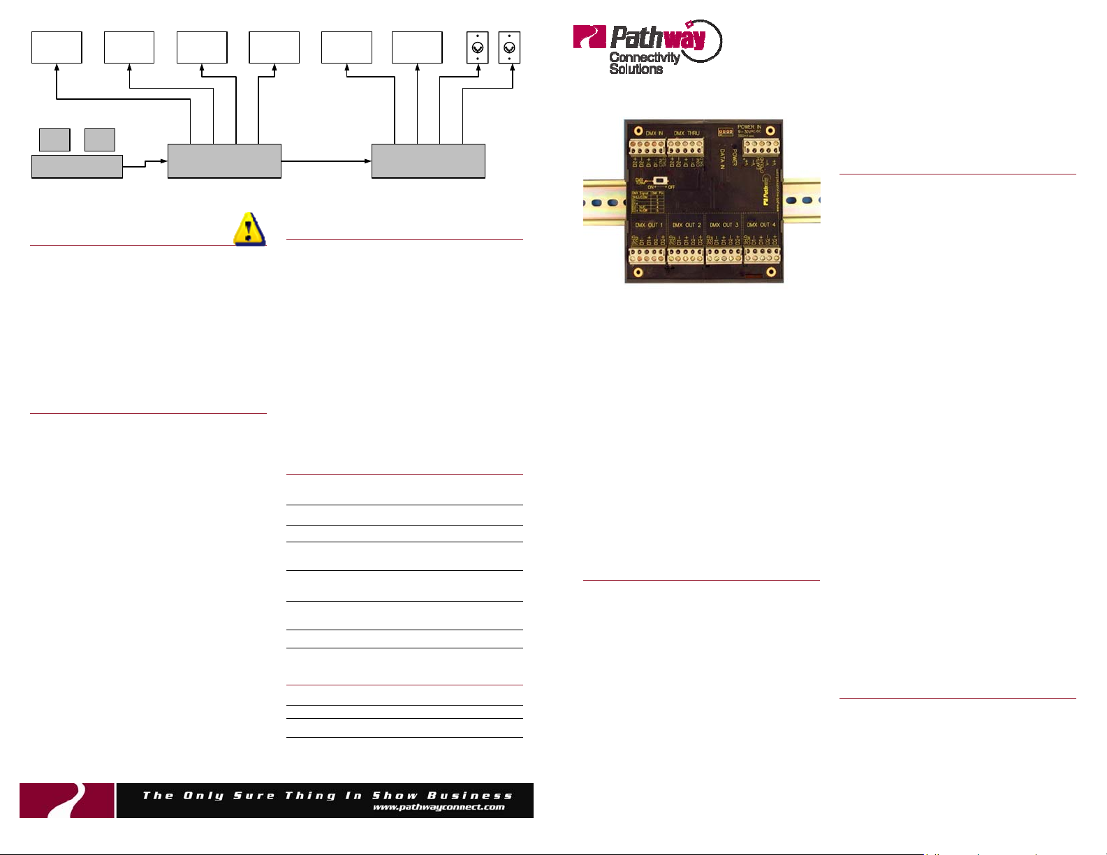
Typical Application
CAUTION!
eDIN modules are designed to work
on voltages from 9-30 volts AC or DC
only. DIN rail power supplies are
readily available from Pathway and
most electrical suppliers.
Each eDIN opto consumes 5 watts of
power.
DMX Termination
If only one eDIN Opto-Splitter is used,
and nothing is connected to the DMX
THRU connector, the terminati on switch
must be set in the ON position to
term i nat e t he i nc omin g D MX s ig nal f r om
the console. If several eDIN optos are
connected together using the DMX
THRU connector on each unit, only the
last eD I N opto i n th e ch ai n i s t erm i na t ed ,
all the others are not terminated (switch
in the OF F p ositio n).
DMX receiving devices such as dimmers
or scrollers are generally provided with a
termination switch, termination jumper or
other means of connecting the required
termination resistance across the DMX
line. Always make sure that the last
receiving device connected to any output
line is properly terminated.
THRU ININ
Indicators
The POWER LED on the face of your
eDIN Opto-Splitter will illuminate when
power is connected to the unit. There is
no on/off switch.
The DATA IN LED will illuminate and
flicker rapidly to indicate that DMX data
is being received.
Each DMX output has an associated
LED to show that the output is operational and DMX data is being transmitted.
Specifications
Required
Power Supply:
Connections: Two-part screw terminals
Isolation: 2500V O pto- isola tion
Protection: Up to 250VAC/DC on all
Protocols: DMX512 , DMX512 -A, or any
Size: 4.64 x 4.5 x 1.5”
Unit Weight: 0.5 lbs. (0.25 kg)
9-30V AC/DC, 5W
port pins
EIA422 /485 based protocol
(118 x 113 x 38 m m)
eDIN Model Des criptions
1002 eDIN 4-Way Opto Splitter
1001 eDIN 15W power supply
1102-30 Additional 12” (30cm) DIN mounting rail
An essential component of any
DMX512 distribution system, the
eDIN Opto-Splitter permits star
wiring installations while isolating
and protecting connected
equipment from harmful electrical
faults. Pathway eDIN optos
feature self-healing protection
devices on all ports to prevent
internal damage when severe
faults of up to 250V are
accidentally applied to the
connected DMX cabling.
Operational Philosophy
To ensure trouble free operation,
DMX512 standards require that DMX
devices be installed in a daisy chain,
wit h no tees, wyes or s tars i n th e DMX
wiring. However, site conditions may
make star wiring desirable or even
mandatory. A Pathway eDIN OptoSplitter permits star wiring by making
each branch of the star function
electrically as its own entity, unaffected
by the other branches of the star.
Additionally, opto-isolation circuitry
prevents ground loops or accidental
damage to control consoles from fault
voltages on DMX lines.
DMX Basics
• All wiring must be in a continuous run,
daisy-chained, no “Tees” are permitt ed
• “Stars” are permitted only in
con junction with a rep eater
• Cable shield may be earth-grounded
at one end only: at the control console
output and the eDIN opto outputs
• Maximum len g t h of o n e cable segment
is 1,800 ft. (550m).
• Receiving devices have male
connectors, transmitters have female
• The last DMX device on the line must
be terminated with a termination
switch or resistor with a value of 100 to
120 ohms between pins 2 and 3.
• 5 pin XLR type DMX connectors are
standard:
Pin 2: Data (-)
Pin 3: Data (+)
Pin 4: Opti onal Data (-)
Pin 1: Common
Pin 5: Opti onal Data (+)
• 3 pin XLR type connectors are a nonstandard alternative:
Pin 2: Data (-)
Pin 3: Data (+)
Pin 1: Common
• Wire must be Belden 9842 (120Ω),
9829 (100Ω), ISO/IEC 11801 (Cat5)
or equivalent
• A maximum of 32 DMX receiving
devices can be present on a single
DMX line
DMX512-A Co mpliance
Thi s pro duc t com pli es wi th t he D MX512 A standard, under the non-compatible
connector (NCC) provision.
All ports are DMX512-A protected to
250V.
Printed in Canada
Subject to change without notice 103 Inglewo od Plaza 1439 17Ave nue SE Calga ry AB, Canada T 2G 1J9 • +1 403 243-8110 Fax +1 403 287-128 1
Page 2
Location
eDIN optos are designed for installation
in an application appropriate NEMA enclosure.
DIN Rail Mounting
The eDIN Opto-Splitter is designed to be
mounted on a section of 35mm DIN rail
secured to the inside of an appropriate
enclosure. The DIN rail included with
the eDIN opto can be used if only one
eDIN opt o is b ein g used . If sever al eDI N
devices are being mounted, you can use
a longer section of 35mm DIN rail, readily available from Pathway as well as
most electrical suppliers.
eDIN modules have no mounting restrictions with regards to positioning within
an enclosure. Modules can be mounted
side-by-side in a continuous row or
spaced out. Clearances between the
modules and the side of the enclosure
are si mil arly st ri ctly a ma tter of avail abl e
space and personal preference. It’s up
to you.
Attach either your own or the enclosed
sect i o n of 3 5 mm DIN r ai l t o t he i nside of
you r enclo sure. Sec ure the eD IN module(s) by first engaging the top of the
eDIN module on the DIN rail. Then,
while pressing both of the release tabs
on the underside of the module, press
the bottom of the module into place.
When properly engaged, the module
should clearly ‘snap’ into place. Check
to ensure that the module as installed is
straight on the rail and the front of the
module should be parallel with the back
of the panel. If not squeeze the release
tabs hard while pulling up on the bottom
of t h e m o d ul e. On c e t h e m od u l e i s f r ee,
repeat the installation process until the
module is correctly and securely installed.
Alternate Mounting
If you do not wish to take advantage of
the DIN r ail m ounti ng sy stem, the eDI N
module can be mounted in a more conventional manner by installing it without
the plastic DIN case. To remove the
plastic case, simply pry the right (or left)
end cap off of the case. You may have
to work the end back and forth to get it
apart. Once the end cap is removed, the
circuit board should slide out.
Use four 0.5” standoffs mounted on 4 x
3.75” centers to install the circuit board
in your enclosure. Make sure that the
components on the underside of the circuit board do not come in contact with
your panel.
Connection Wire
Be sure to use the appropriate wire for
all connections.
DMX Connections: Belden 9829,
9842, Cat5 or equivalent.
Power Connections: Insulated #18-
16 AWG wire, stranded or solid.
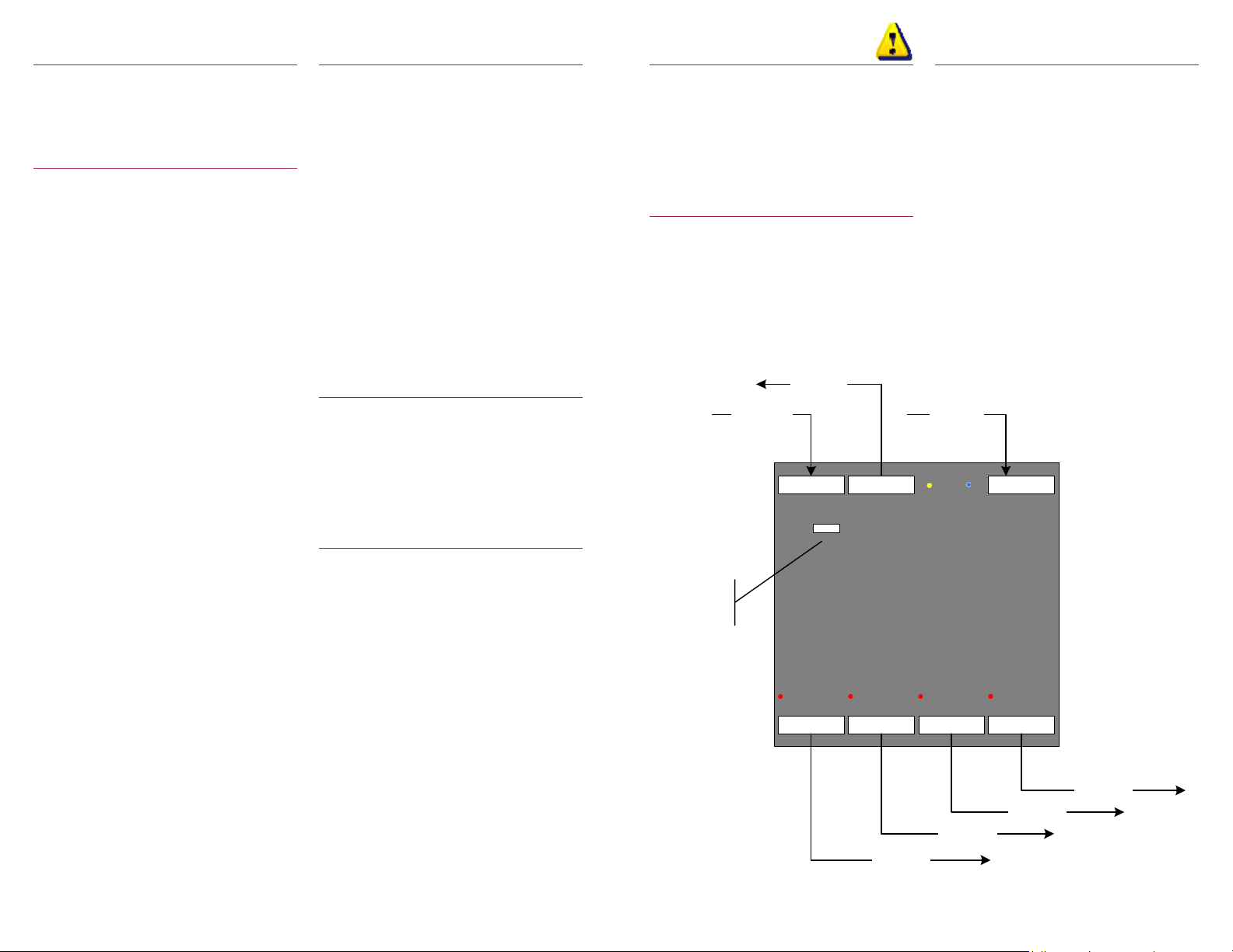
DMX Connections
Typically, Pathway DMX Opto-Splitters
are used in the following configuration:
• DMX IN is connected to the control
console DMX output
• DMX OUTs are connected to the
remote DMX devices or receptacles
for the equipment receiving the
console signal. These may be
dimmers, scrollers or moving lights,
for exam ple.
• DMX THRU passes the console
signal to additional eDIN DMX optosplitters or other similar devices, and
would in turn be connected to DMX
IN on the next unit in line.
WARNING!
All DMX input/output ports must only
be connected to low-voltage data
lines. Do not connect high voltage
sources to these connectors.
Recommended Wiring
Practice
Keep all DMX cabling away from high
voltage/power cables to maintain data
integrity. Wire must be Belden 9842
(120Ω), 9829 (100Ω), ISO/IEC 11801
(Cat5) or equivalent.
To additional
eDINs
From Console
DMX IN DMX THRU POWER
DMX
TERM
ON OFF
Switch should be
OFF if D MX
THRU is used
DMX OUT 1 DMX OUT 2 DMX OUT 3 DMX OUT 4
To DMX gear
Power Con nections
eDIN modules require 9-30 volts, AC or
DC. Each eD IN Opto-Splitter co nsumes
5 watts of power, so size your power
supply accordingly.
With the external power supply turned
off, connect the power leads to one pair
of V+ and V- terminals. Polarity should
be observed if a DC supply is used.
If additional DIN modules are powered
from the same supply, the power may be
daisy-chained using the second pair of
V+ and V- terminals as a ‘thru’ connection.
From supply
POWER
DMX IN
To DMX gear
To DMX gear
To DMX gear
 Loading...