

Page 1

Hydronic
freewatt Plus
®
Model
HDJ
INSTALLATION,
OPERATION &
MAINTENANCE
MANUAL
System,
Information and specifi cations in the manual were in effect at time
of printing of this manual. ECR International reserves the right to
discontinue, change specifi cations or system design at any time
without notice and without incurring any obligation, whatsoever.
Check our website frequently for updates:
www.freewatt.com
P/N # 240008214, Rev. C [01/2011]
www.ecrinternational.com
Page 2
TABLE OF CONTENTS
!
1 - Safety Information........................................ 3
2 - Introduction ................................................. 4
3 - Components, Controls and Accessories ...........12
4 - APC Universal Transfer Switch .......................14
5 - Compatible Room Thermostats .....................17
6 - freewatt Transfer Switch Model FTS-1.8 ........18
7 - Before installing the system ..........................19
8 - Placing the system .......................................22
9 - Exhaust Gas Leak Sensor .............................29
10 - Combustion Air and Vent Pipe ......................31
11 - Gas Supply Piping ......................................33
12 - Electrical Wiring & Connections ....................34
13 - Commissioning and Startup .........................40
14 - Maintenance and Cleaning...........................41
15 - Detailed Sequence of Operation ...................43
16 - Troubleshooting .........................................47
17 - Piping and Wiring Schematics ......................53
Safety Symbols
Manual contains important safety information. Read all
freewatt
and warnings
PLUS
.
System manuals for safety information
!
DANGER
Indicates a hazardous situation which, if not avoided,
WILL result in death or serious injury
!
WARNING
Indicates a hazardous situation which, if not avoided,
could result in death or serious injury.
!
CAUTION
Indicates a hazardous situation which, if not
avoided, could result in minor or moderate injury.
NOTICE
Used to address practices not related to personal
injury.
Energy Star partner, ECR International has
determined the boiler included as part of
freewatt
guidelines for energy effi ciency .
PLUS
System meets Energy Star
Honda MCHP Intertek-ETL Listed,
“Utility Interactive, Cogeneration,
Stationary Engine-Generator Assembly,
Control # 3163904 (US).”
Boiler and HI Module assembly design
certifi ed in US and Canada by Canadian
Standards Association.
2
Page 3
1 - SAFETY INFORMATION
WARNING
!
Fire, explosion, asphyxiation and electrical shock
hazard. Improper installation could result in death
or serious injury. Read this manual and understand
all requirements before beginning installation.
!
WARNING
Do not install this system in mobile home! Boiler is
not approved for installation in mobile home. Doing
so could cause fi re, personal injury or loss of life.
Instructions intended as aid to qualifi ed, service
personnel for proper installation, adjustment and
operation of this system. Read instructions before
attempting installation or operation. F ailure to follow
instructions could cause malfunction of system and
result in death, serious bodily injury. Consult qualifi ed
installer, service agency or gas supplier for assistance
or additional information.
!
WARNING
Do not store or use gasoline or other fl ammable
vapors and liquids, or other combustible materials in
vicinity of this or any other appliance.
Natural gas and propane are normally odorized
by fuel supplier. Odorant may not be perceivable.
Installation of UL and CUL recognized fuel gas
detectors installed in accordance with manufacturer’s
instructions is recommended as additional safety.
Exhaust gases from boiler contain chemicals which
may include carbon monoxide (CO). Carbon
monoxide is odorless, tasteless, clear colorless
gas, which is highly toxic. Even low concentrations
are suspected of causing birth defects and other
reproductive harm.
NOTICE
UL and ULC recognized CO detectors are required
for all buildings equipped with ECR freewatt PLUS
System. All CO detectors should be installed in
accordance with manufacturer’s instructions and
applicable local building codes.
1.1 Safety Information
Check all applicable state, local building codes and •
utility company requirements before installation.
Installation shall conform to these requirements in
their entirety. In absence of these codes, use NFPA,
National Gas and National Electric installation codes
and authority having jurisdiction.
Use only with gas approved for system components. •
Refer to boiler and MCHP unit rating plates.
Provide adequate combustion and ventilation air to •
system space as specifi ed in Section 10, “Combustion
Air and Vent Pipe.”
Combustion products shall be discharged outdoors. •
Connect system components (boiler and MCHP unit)
to approved vent system only, specifi ed in Section 10,
“Combustion Air and Vent Pipe’.
Allow system to cool before servicing. •
Shut off electricity and gas supply connected to system •
before servicing.
Never test for gas leaks with open fl ame. Use •
commercially available soap solution specifi cally made
for detection of leaks to check all connections. See
Section 11, ‘Gas Supply Piping’.
Verify natural gas input rate is correct. Over fi ring •
may result in early failure of the boiler’s components.
Under fi ring may result in too much air for combustion
process causing poor or loss of combustion.
Install boiler to operate within its intended temperature •
range. See boiler ‘Installation Operation & Maintenance’
manual.
Follow regular service and maintenance schedule for •
effi cient and safe operation.
Keep system area clean of debris and free from •
combustible and fl ammable materials.
System is not intended for temporary heating of •
buildings under construction.
System is not do-it-yourself project. Install and servic•
by qualifi ed professionals only.
e
NOTICE
Installation Requirements Specifi c To The State Of
Massachusetts, boiler installation must conform to
Commonwealth of Massachusetts code 248 CMR
which includes but is not limited to: Installation by
licensed plumber or gas fi tter.
3
Page 4

2- INTRODUCTION
2.1 Hydronic
combined heat and power (micro-CHP) system suitable for
residential and light commercial space and water heating
applications up to 200,000 Btu/hr.
freewatt PLUS
• System consists of these main
components:
•
•
•
freewatt
• high effi ciency boiler Model FW95M certifi ed
as Category IV direct vent central heating boiler with
combustion air supplied directly from outdoors through
special air intake system. Combustion products of
freewatt
direct vent system.
Hydronic hybrid integration (HI) module and control •
module integrate
unit into hydronic heating circuit of building.
HONDA MCHP unit, Model MCHP1.2 D & DP, is •
manufactured by HONDA Corporation for use with
freewatt PLUS
For additional details on system components refer to
section 3.
freewatt PLUS
high effi ciency (condensing) boiler•
control module •
hydronic hybrid integration (HI) module •
HONDA MCHP unit•
freewatt • transfer switch
electrical load distribution and management
panel
zone control relays
heat rejection system
Boiler are exhausted to outdoors through
freewatt
System.
Produces electrical power while also generating heat •
in response to building’s nor mal thermostatic heat
demand. The
Produces 240VAC power delivered to main circuit •
panel through 240VAC dedicated circuit.
Certifi ed under UL 2200 - Stationary Generators •
and UL 1741 - Inverters, Converters, Controllers
and Interconnection Sys tem Equipment for Use With
Distributed Energy Resources.
HONDA MCHP unit utilizes indoor air for combustion •
and vents combustion products to outdoors with
PVC pipe. Honda MCHP unit is non-direct vent
appliance.
system is gas-fi red micro-
Boiler and HONDA MCHP
2.2
Application Notes
Maximum design water temperature of 160°F. Heat •
emitters sized for heat output using maximum
design water temperature of 160°F. Heat loss
calculations based on approved industry methods and
outdoor temperature corresponding to design water
temperature appropriate for local area’s weather.
Hydronic•
normal variety of heating loads served by conventional,
multi-zone hydronic heating systems.
freewatt PLUS
base-board radiation, •
radiant fl oor heating, •
domestic hot water via indirect storage tank, •
powered convective heaters, •
hydro-air handlers*•
System may be applied to
NOTE: *Application limited to specifi c air handler models.
Hydronic •
or valves for individual zone temperature control.
Confi guration of hydronic distribution system must be
in form shown in this manual with respect to overall
arrangement of
with respect to zone loads.
See specifi c piping schematics provided for systems •
zoned with circulators and valves and for systems using
air handlers.
freewatt
• Control Module is common to all applications
of hydronic
pump/valve relay controls required for use with pump and
valve-zoned systems and hydro-air systems.
Do not use anti-freeze solution in •
hydronic fl ow loop. Use only good quality water. Install
heat exchanger to isolate anti-freeze solution from main
hydronic system, if particular zone requires anti-freeze
protection.
Priority domestic hot water heating is available and must be •
properly selected in setup of Control Module and ECR zone
controls.
freewatt PLUS
freewatt PLUS
freewatt PLUS
Appropriate pump/valve relay control from ECR •
family of zone controls must be used as supplied with
freewatt PLUS
See specifi c electrical wiring diagrams provide for •
circulator zoned systems, valve zone systems, and
systems with air handlers.
Indirect water heater aquastat setting must be between •
120 to 125°F.
Mixing valve must be used on domestic water supply •
outlet of any indirect water heating tank applied with
freewatt PLUS
Systems use circulators
Boiler and MCHP unit
System. Different ECR zone
System.
freewatt PLUS
. Do not use set back.
System
4
Page 5
2- INTRODUCTION
!
WARNING
Burn and scald hazard. Failure to install mixing
valve will result in hot water scalding hazard.
Install mixing valve per manufacturer instructions.
Hydronic system is supplied with •
thermostat. Utilize thermostat on single “Smart Zone” only.
Select “Smart Zone” as zone with largest heating demand
(not domestic hot water zone) typically the largest space
heating zone on fi rst fl oor of two story home.
PLUS
benefi t if Smart Zone represents at least 25% of total home
heating load. Consider combining zones to achieve desired
heat load for Smart Zone if there is no single large zone in
existing distribution system, but many small zones.
freewatt
• communicating thermostat is directly wired to
freewatt
zones, with compatible conventional heating thermostats
(new or existing) may be connected directly to
Control Module circuit board. If more than compatible six
zones (including priority domestic hot water and Smart
Zone) are needed
expanded to include additional heating zones. Additional
ECR zone controls may be required.
Hydronic•
phased. Install
in required piping confi guration as shown in
leaving installation, commissioning, and operation of MCHP
to later date (cap off piping connections to MCHP), if need
to supply heat to building quickly as possible.
PLUS
normal loads if MCHP unit is not available for operation.
MCHP unit will provide signifi cant portion of annual •
heating energy needed in home, MCHP unit alone
cannot be expected to meet all desired comfort and/or
freeze protection needs. Maintaining operation status of
freewatt
essential to meeting all comfort and/or freeze protection
needs.
“CHP MODE” switch OFF position conveniently •
separates and maintains boiler heating function while
disabling operation of MCHP unit and generation of
electric power. This is Bypass Mode of operation.
System will produce best electric power generation
Control Module circuit board. Additional fi ve
freewatt PLUS
freewatt PLUS
freewatt PLUS
boiler will provide suffi cient heating capacity to meet
Boiler as part of
freewatt
System can be
System installation may be
Boiler and Control Module
freewatt PLUS
communicating
freewatt
freewatt
Section 17
freewatt
System is
,
Installation of UL and ULC recognized CO detectors with •
audible alarms (not supplied with system) are required
part of
Exhaust Gas Detection System included part of
PLUS
tion of building inhabitants from potentially dangerous high
levels of carbon monoxide. Install both Exhaust Gas Detection System and separate, independent UL recognized CO
Detectors.
Installation of two different outdoor temperature sensors is •
required for proper operation of hydronic
System, both are supplied. One (Honeywell) connects
directly to boiler and other (Tekmar) to
Module.
hydronic •
electric power during power outage if installed and commissioned per Installation, Operation, and Maintenance Manual.
Heating system must be connected to APC UTS.
Installation, setup, commissioning and maintenance of •
freewatt PLUS
PLUS
ning Windows XP or Vista with working serial connection.
Call •
watt PLUS
additional information.
Heat rejection kit (sold separately) required for instal-•
lation.
Zone Valves with their own 24 VAC power supply may •
be used on zones 3-6. Refer to Electrical Wiring and
Connections section for detailed information on use of
steering relays in
freewatt PLUS
System does not provide audible alarm for protec-
freewatt PLUS
System requires use of
MINT software tool loaded on laptop computer run-
freewatt PLUS
System installations above 3,300 feet and for
Water cooled heat rejection kit used when there •
is uninterruptable supply of water during power
outage. Kit ties into main water supply line and
discharges water to appropriate drain.
Air cooled heat rejection kit used when there is •
not uninterruptable supply of water during outage
(houses with well pumps). Air cooled heat rejection
system is vertically arranged side discharge fan-coil
unit with closed coolant loop designed for outdoor
installation.
installation.
System will generate heat &
Technical Support Line for
freewatt control module.
freewatt PLUS
freewatt
freewatt PLUS
freewatt
freewatt
Control
free-
Full heating operation of hydronic •
is not dependent on maintaining working connection to
Internet. Lack of internet connection will prevent remote
communication with system by homeowner or service
provider.
freewatt PLUS
System
5
Page 6

2- INTRODUCTION
2.3 Save These Instructions
Read this manual carefully and keep for future reference by
service technician. Manual is considered permanent part of
your Hydronic freewatt
with system.
Manufacturer is not responsible for any fi eld installation
changes made to system installation that are not described
or acknowledged in this manual.
Product must be installed by licensed plumber or gas fi tter
when installed within Commonwealth of Massachusetts.
Appliance has been equipped for residential installations.
If used for commercial applications, all code requirements
must be adhered to for installation. May require additional
controls or system components.
2.4 Read All Documents
Hydronic •
Information Manual.
freewatt PLUS
PLUS
System and should remain
(Model HDJ) User’s
freewatt
• FW95M-200 Boiler Installation, Installation,
Operation and Maintenance Manual, Parameter Guide,
Control Manual & Troubleshooting Guide.
HONDA MCHP, Model1.2D and MCHP1.2DP, Type UCFJ, •
Installation Manual and Owner’s Manual.
HAI Thermostat Installation Instructions and Owner’s •
Manual
Applicable ECR Zone Control Manual•
freewatt
• Indirect Water Heater Set-up, Operating &
Maintenance Instruction Manual
freewatt
• Transfer Switch Installation, Operation and
Maintenance Manual.
APC Universal Transfer Switch Site Preparation and •
Installation Guide.
Hydronic •
Installation, Operation and Maintenance Manual.
freewatt
(model HDJ) Control Module
6
Page 7
2- INTRODUCTION
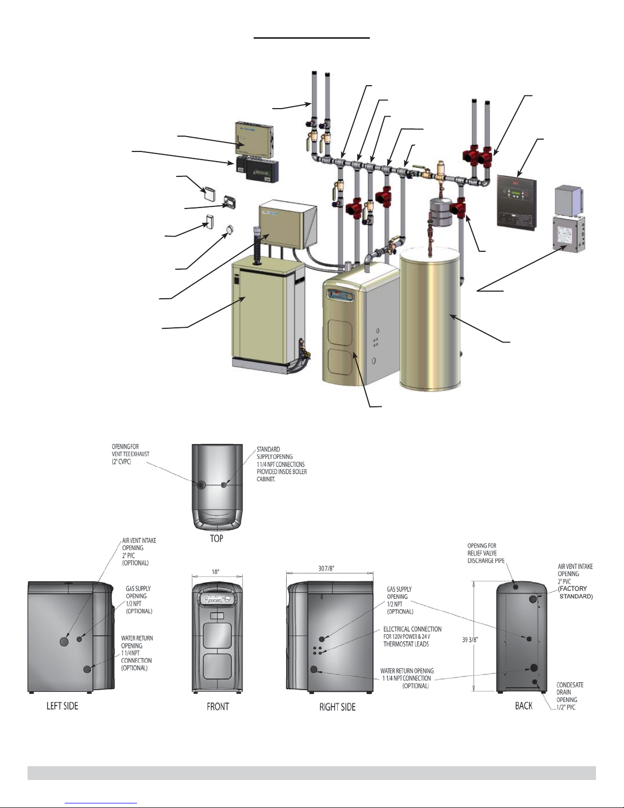
Figure 2-1 - freewatt PLUS System Components ( Zoned with Circulators)
freewatt® PLUS System Components
Heating Zone Returns
freewatt System Control Module
Zone Controls
Honda MCHP Exhaust Gas Sensor
Programmable & Communicating HAI
Thermosat
freewatt Outdoor Temperature
Sensor
Boiler Outdoor Temperature Sensor
HI Module
Honda MCHP
From DHW
To HI Module
From HI Module
To Boiler
From Boiler
Heating Zone
Circulators
APC UTS6H
DHW Circulator
freewatt Transfer
Switch W/Load
Balancing Transformer
freewatt Indirect
Hot Water Heater
Figure 2 -2
freewatt PLUS
freewatt Boiler
95% AFUE
Boiler
7
Page 8
Table 2-1 System Rating and Sizing
2- INTRODUCTION
Unit
MCHP Mode
Input
(MBH)
Heating
Capacity
(MBH)
18.4 12.3 12.3 1.2 180
Overall
Effi ciency
(%)
Nominal
Power
(kWe)
Weight
(lbs)
Honda
MCHP Unit
Backup Mode
18.5 - 26 12 - 17 12 - 17 0 - 1.8 180
(0 - 3,300’)
Boost Mode
Boiler
Boiler Module (0 - 2,000’)
Ratings are for sea level applications.
Boiler: Consult boiler Installation, Operation and Maintenance Manual for high altitude conversion and derating
instructions.
Honda MCHP: Consult with ECR International Technical Support for high altitude conversion and derating instructions
Boiler manual has I=B=R Net Rating (MBH) data for system design.
Proper application of Hydronic
Relatively lower heat output of MCHP unit, priority heating device, and automatic modulation of fi ring rate of condensing
boiler allows Hydronic
performance depends signifi cantly on sizing of heat distribution system relative to actual space heating demands.
Under-radiated distribution systems that require high system water temperatures (above 180°F during design (coldest)
day outdoor temperature conditions) will signifi cantly compromise electric generation performance of
System. Recommend hydronic heating system be designed for 160°F or lower water temperature to produce greatest
annual electrical power generation and highest energy effi ciency. 160°F design water temperature may require
installation of new radiation or re-confi guration of existing radiation to acceptably heat zones.
freewatt PLUS
freewatt PLUS
System to be applied to wide range of loads without effi ciency penalty. System
26 17 17 1.8 180
80-200 76-190 95% - 284
System requires assessment of heat loss and applied building needs.
freewatt PLUS
Hydronic
and boiler delivering high heat.
hours will maximize system’s electrical power production. Boiler will fi re to provide heat if additional heat is needed or
anticipated.
Boiler will automatically modulate in range of 80,000 to 200,000 BTU/hour, and MCHP unit will continue to run to
provide needed level of heat supply in high heat mode. Hydronic
programmable outdoor temperature reset of hydronic system water temperature to provide uniform heating.
freewatt PLUS
System operates with two levels of heat: HONDA MCHP’s thermal output delivering low heat
freewatt PLUS
uses proprietary heating algorithm to ensure long MCHP operating
freewatt PLUS
System operates with automatic and
8
Page 9
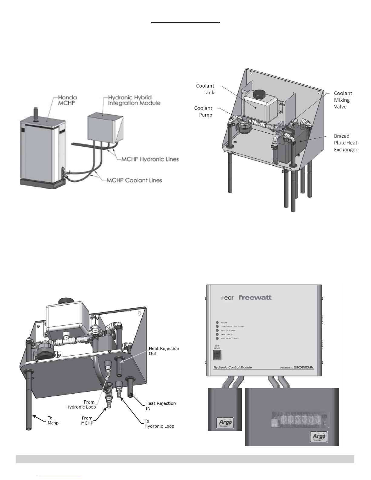
2- INTRODUCTION
Figure 2-3 MCHP & Hydronic Hybrid Integration
Module
Figure 2-4b Hydronic Hybrid Integration Module
Figure 2-4a Hydronic Hybrid Integration Module
Figure 2-5 Typical freewatt PLUS Control
Module Confi guration
9
Page 10
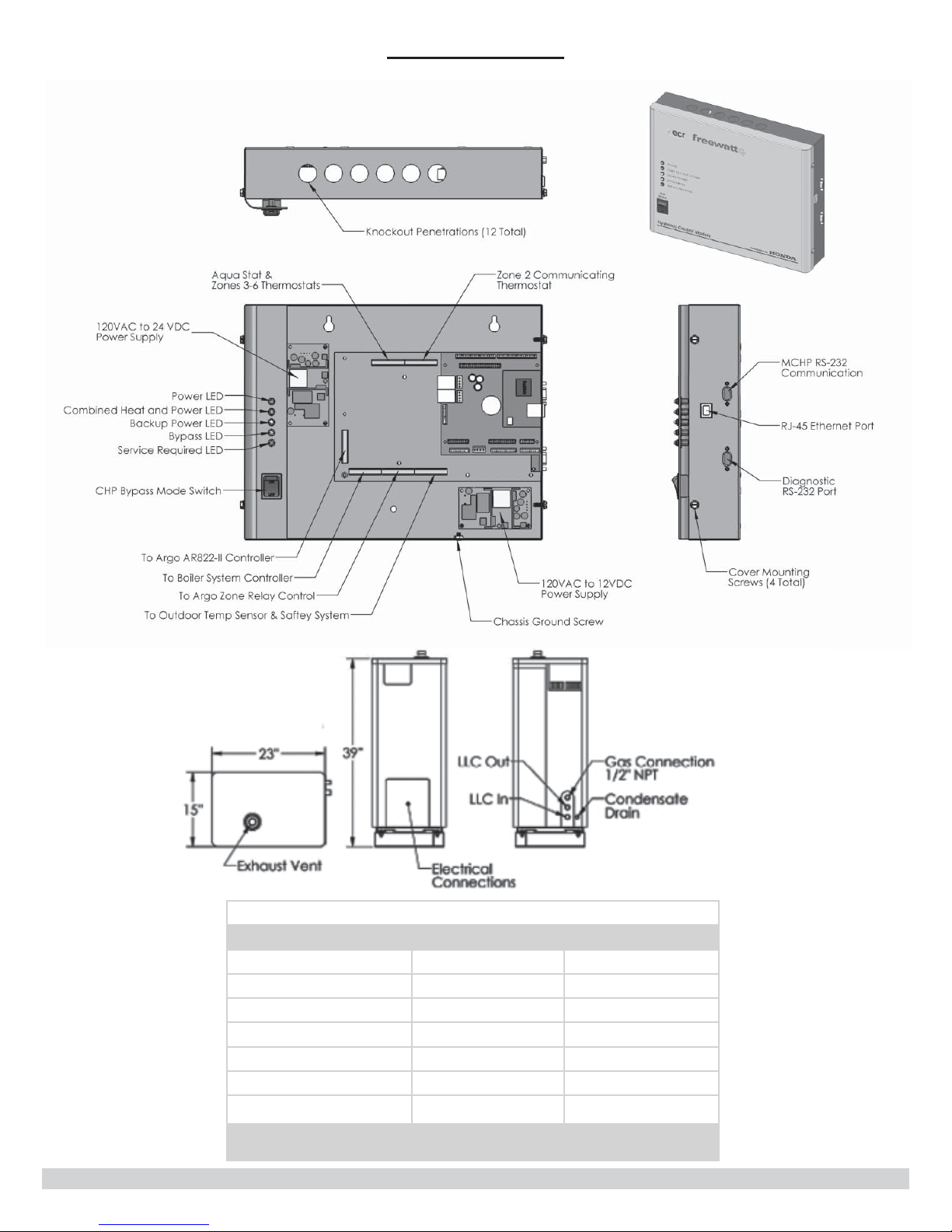
2- INTRODUCTION
Figure 2-6 freewatt PLUS Control Module Details
Figure 2-7 MCHP Dimensions
Dimensions Boiler Honda MCHP
Top 1" ( 8" for service) 14"
Sides 1" (24" for service) 0.4" (12" for service)
Base See Note 1 See Note 2
Front 0" (24" for service) 0.4" (20" for service)
Rear 6" 0.4" (2" for service)
Intake/Vent Piping 0" 0"
Near Boiler HW Piping 1" 0"
System Clearances to Combustibles
NOTE: 1. Combustible fl oor approved, but not carpet.
2. MCHP attached to base anchored to concrete fl oor .
10
Page 11

2- INTRODUCTION
Figure 2-8 MCHP Electrical Connection Details
Figure 2-9 MCHP Front Interface Details
11
Page 12

3 - COMPONENTS, CONTROLS AND ACCESSORIES
Section provides brief description of components,
controls, and accessories of hydronic freewatt PLUS
System.
3.4 HONDA MCHP Unit
3.1 Boiler
Refer to separate freewatt boiler documentation for
detailed information on the freewatt boiler.
3.2 freewatt Control Module
freewatt • control module monitors and controls
operation of Hydronic freewatt PLUS System.
Sensing inside and outside temperature as well as
other system temperatures and settings, proprietary
heating algorithm controls operation of Honda
MCHP optimizing power production and low level
heat delivery.
freewatt • control module includes relay/interconnect
board, DC power supply, and advanced singleboard computer board incorporating powerful
microprocessor, RS-232/RS-485 serial ports, and
10/100 Base-T Ethernet port.
3.5 Smart Zone Communicating Thermostat
3.3 freewatt PLUS Hydronic Hybrid Integration
(HI) Module
freewatt PLUS • Hydronic HI Module location is
where heat in MCHP coolant is transferred into
hydronic water.
freewatt PLUS • Hydronic HI module consists of
brazed plate heat exchanger, mixing valve, coolant
reservoir and coolant pump.
Hydronic water is pumped through secondary circuit, •
MCHP coolant is pumped through primary circuit.
Mixing valve is fi eld adjusted to deliver minimum •
152°F coolant to pump, which returns coolant to
Honda MCHP unit.
Coolant reservoir holds spare coolant and is •
instrumental in proper commissioning of system.
Hydronic HI Module designed to mount on •
adjacent wall or on side of boiler. Module’s brazed
plate heat exchanger has two ¾” NPT hydronic
water connections and two ¾” NPT coolant loop
connections connected to HI module
Hydronic water circulator for HI module is mounted •
external to HI module as part of hydronic system
piping.
freewatt • control module operates both HI module
coolant pump and hydronic circulator suppling
hydronic water fl ow to HI module. Coolant pump
operates on 24VDC supplied directly by freewatt
control module. Associated 120VDC hydronic
circulator is powered through ECR AR822-II relay
control.
3.6 Outdoor Temperature Sensor
3.7 Internet Connection
Connecting control module to high-speed internet
service allows freewatt PLUS service provider to
monitor system’s operating characteristics. freewatt
control module will notify service provider of
abnormality, if system has operating characteristics
outside normal operating range and remote monitoring
system is enabled and active.
Honda MCHP Unit is custom-engineered micro-•
combined heat and power module integrated into
Hydronic freewatt PLUS System. MCHP unit
designed to start and stop by means of digital signal
from control module when control module senses
there is heat demand in dwelling.
MCHP unit is ETL certifi ed for grid interconnection •
if your utility allows, unit can deliver electrical
power back into electric grid. Unit provides system
operating data and diagnostic data to control
module.
Smart zone communicating HAI thermostat •
communicates directly with control module. Allows
freewatt control module to download thermostat
settings and maximize system’s electrical power
generation, providing higher level of comfort to
dwelling.
Zone which thermostat is applied is referred to as •
“Smart Zone”. Supplied communicating thermostat
must be used on one space heating zone of hydronic
system. freewatt PLUS System will not work with
any other thermostat installed in “Smart Zone”.
Compatible conventional thermostats, may be used
in other zones.
Hydronic • freewatt PLUS System uses two outdoor
temperature sensors to anticipate heat demand
within dwelling by tracking outdoor temperature.
Control module will determine optimum temperature
to activate Honda MCHP unit and provide thermal
comfort, maximizing generation of electrical power
as outdoor temperature falls.
Honeywell temperature sensor is connected directly •
to freewatt PLUS Boiler and Tekmar temperature
sensor is connected directly to freewatt Control
Module.
Both sensors are required for proper operation. •
Route in separate cables at least on foot apart to
ensure signal quality.
12
Page 13

3 - COMPONENTS, CONTROLS AND ACCESSORIES
3.8 Website
freewatt control module web site address is assigned
to system at time of installation allowing homeowner
and service provider to monitor or control system’s
operation.
3.9 External Condensate Pump
Float activated condensate pump with integral •
sump is required for installation where there is no
fl oor drain or other appropriate drainage receptacle
available to receive condensate from system (boiler
and MCHP unit).
Condensate pump can be piped to remote point to •
sanitary sewer system (Please follow all state or local
regulations regarding disposal of condensate). Install
system so proper pitch can be placed on piping to
deliver condensate safely to external condensate sump.
3.10 Exhaust Gas Leak Sensor
Exhaust Gas Leak Sensor (EGLS) monitors integrity of •
Honda MCHP unit combustion system and shuts down
MCHP unit if certain potentially unsafe conditions are
detected.
Monitors carbon monoxide level in air space near MCHP •
unit.
Exhaust Gas Leak Sensor is independent and separate •
from audible CO alarming system installed with
freewatt PLUS
practices for all fuel-fi red central heating equipment.
Proper installation of the EGLS is required to •
commission Hydronic
System in compliance with best
freewatt PLUS
System.
3.11 Concentric Vent/Air Intake Termination
(Optional)
Optional concentric vent/air intake termination utilizes •
single opening for boiler through wall or roof of
structure.
MCHP unit requires use of exhaust vent.•
3.12 Heat Rejection System
Heat rejection kit (sold separately) is required for backup
mode operation during times when no space heating or
water heating is required.
A water cooled heat rejection system is available •
for installations where there is uninterrupted supply
of water during power outage (city water). Kit ties
into main water supply line and discharges water to
appropriate drain. Drain must be suitable for 0.35 GPM
at 180° F. Kit contains ball valve, pressure reducer,
electronic ball valve, and fl ow reducer. Installer must
supply piping to tie into main water line, and deliver
water to appropriate drain.
Installations without uninterrupted supply of water •
during power outage (most houses with well pumps)
air cooled heat rejection system is available.
Contains vertically arranged side discharge fan-coil
unit installed outside, and is connected to HI Module
through closed coolant loop. Dimensions of unit are
24” Length, 15” Width, and 36” Height.
Air cooled heat rejection system installer must •
supply secure mounting pad or foundation, power
wiring, low voltage wiring (18 AWG minimum),
and closed Propylene Glycol coolant loop from
HI Module to unit (3/4” piping, circulator, air
separator, pressure relief valve, expansion tank,
fl ow check, and purge valve). See FWHRJ Air
cooled heat rejection system Installation, Operation,
Maintenance manual for specifi c installation
instructions.
3.13 Display/User Interface
Homeowner can scroll through control settings and
change operating settings to customize freewatt PLUS
System operation using PC.
3.14 Internet Connection & Commissioning
freewatt • System control module connects to
customer’s home network in same way any
computer or other network appliance does
connecting via Ethernet connection available on
most routers. freewatt PLUS connection uses
10/100 Mbit/s wired Ethernet connection, wireless
bridges may be used when wired connection isn’t
possible.
freewatt • control module is assigned static address
outside of DHCP range available from router.
IP address, netmask, gateway and DNS addresses •
are programmed into control module using
freewatt PLUS service tool. Common confi guration
(with router at address 192.168.1.1) would have
freewatt address set to 192.168.1.200, netmask
set to 255.255.255.0, gateway set to 192.168.1.1
and DNS entries set to 208.67.222.222 and
208.67.220.220 (addresses for Open DNS).
Router confi gured to allow incoming traffi c for •
diagnostics and (if requested by customer) access
to user web page. Routers refer to these settings as
‘port forwarding’, ‘applications’’, or ‘virtual servers’.
Refer to router manufacturer’s documentation.
Remote diagnostics require port 4500 be directed •
to freewatt control module. Port for customer web
pages is confi gurable - usually set to 8082 because
many ISPs (Internet Service Provider) block use of
standard port 80.
Number of wireless bridge or gaming bridges •
have been tested to work with control module if
wireless confi guration is required. Confi gure using
manufacturer’s instructions.
13
Page 14
4 -APC UNIVERSAL TRANSFER SWITCH CONFIGURATION
NOTICE
APC universal transfer switch is provided for use
with freewatt Plus system and is not intended
for emergency backup power applications.
Manufacturer is not responsible for the use of this
switch in any manner not outlined in this manual or
APC UTS6H Installation Guide.
4.1 APC Universal Transfer Switch
freewatt•
Transfer Switch as load panel in Back-Up Power Mode.
UTS6H requires customized confi guration in order •
to operate effectively with freewatt
Following section will explain confi guration process for
this component.
Set-up for APC Universal Transfer Switch (UTS6H) •
involves following System Confi guration and Setup
section in UTS’s Installation Guide.
Important notes about this product:•
Improper confi guration may result in improper
operation of freewatt PLUS System in Backup Power
Mode. Failure to follow these instructions could cause
malfunction of system and result in death, or serious
bodily injury. Read and follow these instructions
before attempting installation, commissioning or
operation.
PLUS
System incorporates APC Universal
!
WARNING
PLUS
System.
Circuit 5 & 6
Although all UTS circuits do not need to be used, •
Circuits 5 & 6 must be connected to main circuit panel
and must receive power for UTS to function. Circuits
5 & 6 must also be connected to circuits that are in
opposite phases, so 240V is present across two circuits.
Allows UTS6H to monitor Utility power supply.
4.2 Uninterruptible Power Supply (UPS)
If using UPS to power “uninterruptable” loads, plug UPS •
power input cord into convenience outlet to charge UPS
batteries when MCHP Backup Power is available. Note,
UPS batteries will also be charged from convenience
outlet when grid power is available.
Follow UPS and UTS6H instructions for sizing UPS for •
loads confi gured to be powered by UPS in Backup
Mode. Typically, low power circuits, such as computers
or security systems, are confi gured for use with UPS.
4.3 Non-Delayable & Delayable Circuits
Circuit assigned to • freewatt boiler shown in examples
on Circuit 3 must be confi gured as “Delayable-No” to
ensure freewatt
when in Backup Mode, otherwise system may not
operate correctly.
All other circuits must be confi gured as “Delayable-•
Yes” except in case of example where UPS is used
and circuit source is confi gured as “UPS” or “Un-
interruptable”.
PLUS
System always has power
NOTICE
Use only outlet mounted AFCI and GFCI circuit
interrupters with the UTS. Do not connect the UTS
to circuits utilizing AFCI or GFCI circuit breakers in
the main electrical panel.
Circuit 1
Circuit 1 includes Load attached to Circuit-labeled “1” •
and convenience outlet on front of UTS6H, together
must consume less than 15 amps when system is
operating in Backup Mode. If not using Uninterruptable
Power Supply (UPS), it is recommended to use circuit
1 to power freewatt
condensate pump.
Circuit 1 is only powered by MCHP when in Backup •
Power Mode. It will not be powered from UPS if
UTS6H is equipped and confi gured to use UPS. It
is recommended that UPS be plugged into front
convenience outlet and therefore is powered by Circuit
1.
PLUS
System’s low power
4.4 Hardwire Kit
UTS6H is supplied with Hardwire Kit used to connect •
freewatt
Parts, Kits & Optional Accessories for kit part number.
Hard-wire kit is installed in UTS6H and accepts cable
delivering Honda generator’s backup power output.
Follow electrical schematics in this manual and
instructions in Hard-wire Kit for installation.
PLUS
Transfer Switch to UTS6H. See
NOTICE
Circuits 5 & 6 must be connected to circuits in
opposite phases to ensure 240VAC is present across
two circuits, to allow UTS6H to monitor utility power
supply and sense power outage.
NOTICE
Mark all breakers in Electric Panel as moved to
UTS6H for future reference.
14
Page 15
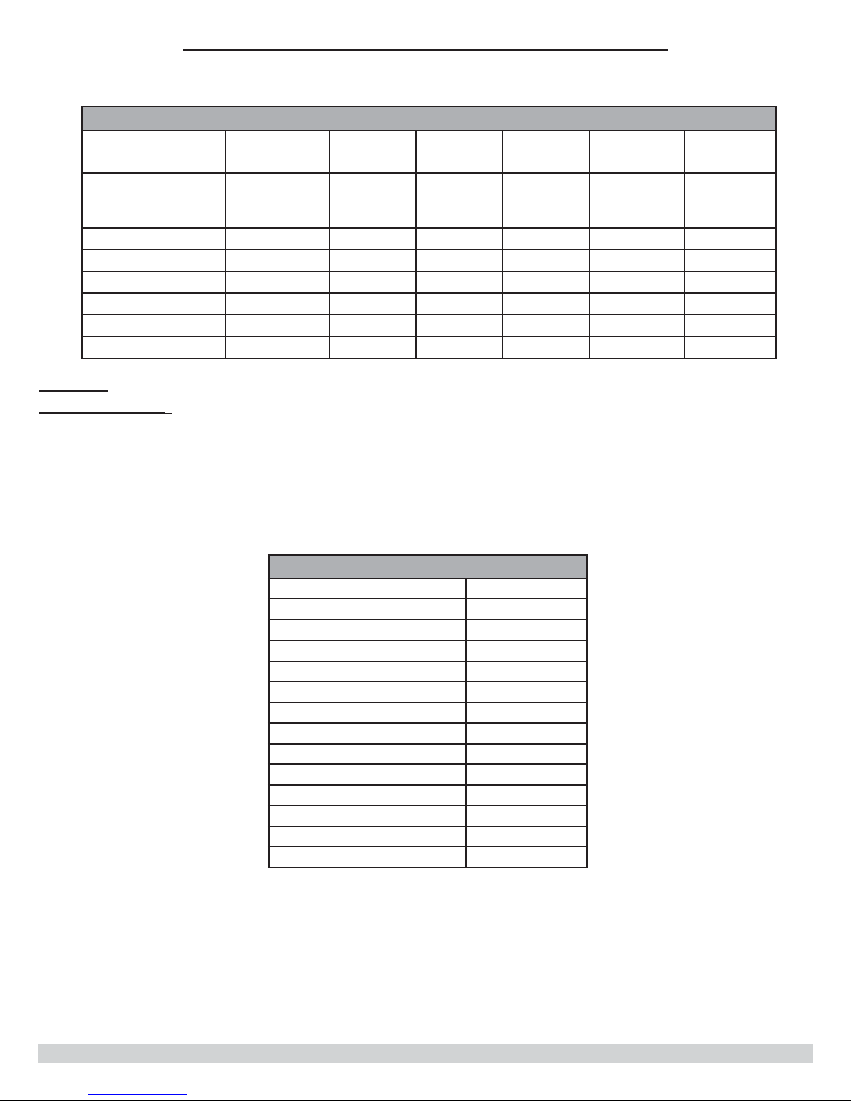
4 - APC UNIVERSAL TRANSFER SWITCH CONFIGURATION
Table 4-1 Typical UTS6H Circuit Setup without UPS
Typical UTS Circuit Setup without UPS
PARAMETER
CIRCUIT
I
Other (con-
Load Type
densate
pump)
Source GEN GEN GEN GEN GEN GEN
Delayable Yes Yes (1) No Yes Yes Yes
Max time off (min) 30 1 30 5 60 30
Min time on (min) 30 2 30 5 60 15
Security Mode Off Off Off Off Off Off
Amp Rating(A) 15 15 15 15 15 15
Note (1)
Delayable - Yes:
or sump pump from losing power when in Backup Mode. If sump pump and boiler may operate at same time (power outages during heating season and heavy rain events), possible solutions include:
Battery-backed sump pumpA.
UPS and confi gure sump pump power source as “Either” UPS or Generator.B.
Setting is required for Warm Air freewatt
CIRCUIT2CIRCUIT3CIRCUIT4CIRCUIT5CIRCUIT
6
Sump
pump
Boiler Computer
PLUS
System boiler to prevent freewatt
Security
System
Refrigerator
PLUS
System
Table 4-2 Typical UTS6H System Setup without UPS
Typical UTS6H System Setup without UPS
Bypass mode No
Load shedding? On
Voltage sensitivity Medium
Time Management On
Reset Energy Meter No
System Test No
Backup1 Source Type Generator
GEN power rating 1700 (1)
GEN SRGE Overload Time 0 seconds
GEN Start Mode manual
Backup2 Source Type none
GEN power rating 1800
GEN SRGE Overload Time 0 seconds
Reset to default no
NOTE:
(1) Available generator power is set to 1,700 watts to account for 100 watt power consumption of load balancing
transformer.
15
Page 16
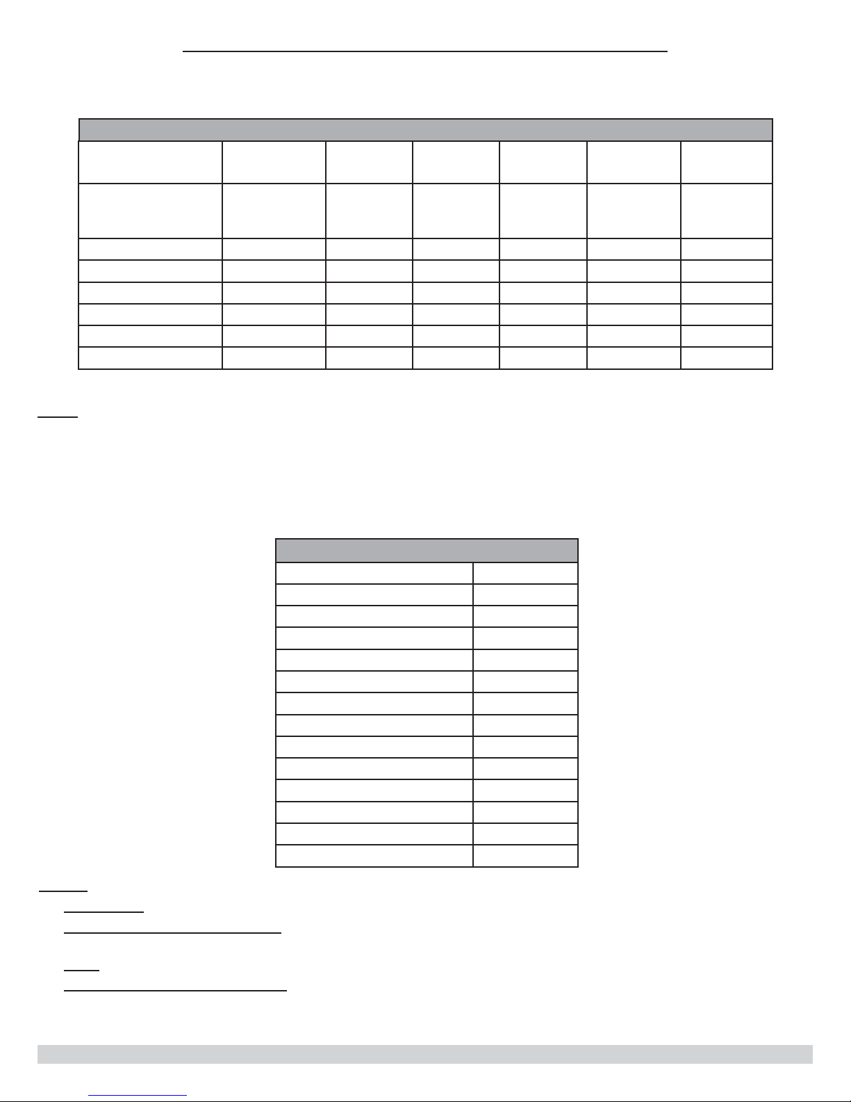
4 - APC UNIVERSAL TRANSFER SWITCH CONFIGURATION
Table 4-3 Typical UTS6H Circuit Setup with UPS
Typical UTS Circuit Setup with UPS
PARAMETER
Load Type
Source GEN EITHER GEN EITHER EITHER GEN
Delayable Yes Yes No Yes Yes Yes
Max time off (min) 30 1 30 5 60 30
Min time on (min) 30 2 30 5 60 15
Security Mode Off Off Off Off Off Off
Amp Rating(A) 15 15 15 15 15 15
Note: UPS power output cord shall be attached to “UPS” inlet port of the UTS6H.
CIRCUITICIRCUIT2CIRCUIT3CIRCUIT4CIRCUIT5CIRCUIT
Other (con-
densate
pump)
Sump
pump
Boiler Computer
Security
System
6
Refrigerator
Table 4-4 - Typical UTS6H System Setup with UPS
Typical UTS6H System Setup with UPS
Bypass mode No
Load shedding? On
Voltage sensitivity Medium
Time Management On
Reset Energy Meter No
System Test No
Backup1 Source Type Generator (1)
GEN power rating 1700 (2)
GEN SRGE Overload Time 0 seconds
GEN Start Mode manual
Backup2 Source Type UPS (3)
GEN power rating 2100 (4)
GEN SRGE Overload Time 0 seconds
Reset to default no
Notes:
Generator:1. Corresponds to 240VAC GEN port on UTS6H.
GEN Power Rating (Backup1)2. : Set to 1,700 watts to account for 100 watt power consumption of load
balancing transformer.
UPS:3. Corresponds to UPS inlet port on UTS6H.
GEN Power Rating (Backup2):4. Corresponds to 1,700 watts of MCHP power PLUS UPS power rating (in this
case 400 watts).
16
Page 17

5 - COMPATIBLE ROOM THERMOSTATS
5.1 freewatt Hydronic Zone Thermostat
Requirements
Select heat or heat/cool thermostat with following
properties, except Zone-2. Zone 2 must use HAI Smart
Zone Thermostat.
Use isolated relay contacts to switch W call for heat •
signal.
to thermostat’s “R” terminal to pass directly thru
thermostat’s W relay to drive “W” signal back with
minimal loss of signal voltage when calling for heat.
Thermostat’s W relay must present high-impedance •
(ie. no current fl ow) when open, not calling for heat.
Thermostat must not add resistive elements to W •
signal path (resistors, voltage divider networks,
MOSFET(s), transistors, etc.) when not calling for
heat. Open circuit impedance of W signal path must
be greater than 100,000 ohms, and preferably higher
(ie 1 Megohms or more).
5.2
Known Problematic Thermostats:
Honeywell T87N, T87K
•
:
freewatt
expects 24VAC “HOT” connected
Voltage must be greater than 20 Volts AC, when •
thermostat calls for heat. Thermostat is not suitable
for use with
less than 20 Volts AC.
5.5 Communication Registers On RC-1000 Smart
Zone Thermostat:
Apply factory reset to restore communications on RC-•
1000-WH-ECR.
Select “Setup”. •
Select “Installation Settings”. •
Notice warning for installers. Press “Continue”.•
Select “Factory Reset” (last item in list). •
Press “Back” as required to return to normal operation. •
All settings, including setback programming have been
cleared.
freewatt PLUS
P
ress (“click”) on scroll wheel to start.
System if voltage is
5.3
Known
HAI Omnistat1, Onmistat2•
LUX 1500•
Braeburn Model 3000•
Compatible thermostats:
5.4 Tests For Thermostat Compatibility:
Resistance test: •
Thermostat calling for heat, W relay closed: •
Thermostat relay impedance must be less than 40
ohms when measured across thermostat R and
W terminals. Impedance greater that 40 ohms
is unacceptable and will not work reliably with
freewatt PLUS
Thermostat not calling for heat, W relay open: •
Thermostat relay impedance should be greater than
1 Megohm (1 million ohms).
Voltage test:•
AC voltage measured between 24V common •
terminal on circuit board J02 connector (labeled
24VAC - bottom of board) and circuit board J02 W1,
W3 or W4 terminals (top of board) must be less
than 1.5 Volts AC when no call for heat, attached to
freewatt PLUS
volts AC from
not suitable for use with
voltage is greater than 1.5 Volts AC.
System.
System and powered by 24 to 28
freewatt
Control Module. Thermostat
freewatt PLUS
System if
17
Page 18
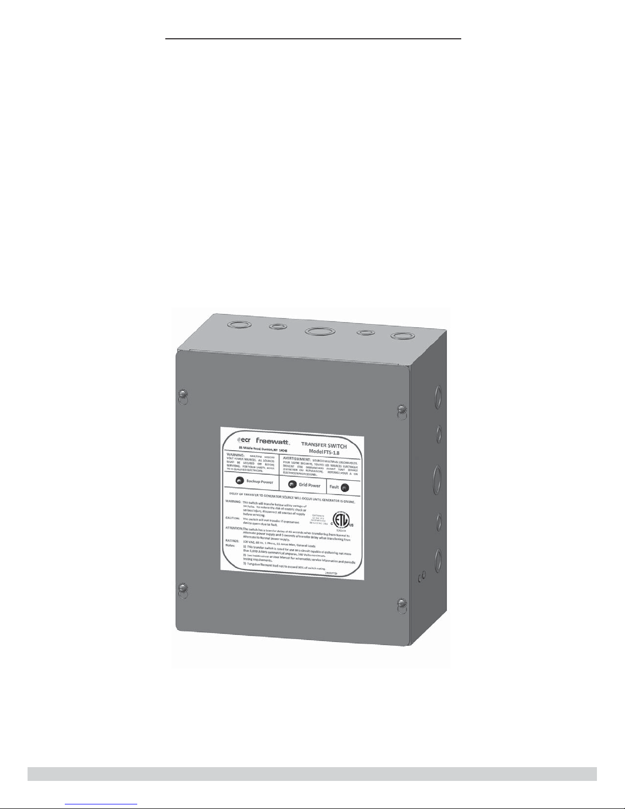
6 - freewatt TRANSFER SWITCH MODEL FTS-1.8
6.1 freewatt Transfer Switch Model FTS-1.8
freewatt• Transfer Switch is specifi cally designed for
use with freewatt
power (micro-CHP) system.
freewatt•
of electric load from utility power source to MCHP unit.
No manual adjustments or switching are required by
homeowner under normal operation.
freewatt• System Control Module and freewatt
Transfer Switch monitor utility power source for failure.
Monitor HONDA MCHP power source for electrical power •
output and proper operating conditions.
Transfer Switch provides automatic transfer
PLUS
micro-combined heat and
Figure 6-1 freewatt Transfer Switch
freewatt• Transfer Switch provides freewatt
product line with reliable means of providing backpower to critical loads while preventing electrical
feedback to utility from MCHP.
PLUS
freewatt•
and is limited in type, wattage, and number of loads
supported.
freewatt•
freewatt
PLUS
Consult • freewatt Transfer Switch Installation,
Operation, and Maintenance manual for installation,
operating and troubleshooting information.
System by qualifi ed installer.
provides backup power up to 1.8 kW
Transfer Switch certifi ed for use as part of
PLUS
System. Only install with freewatt
PLUS
18
Page 19

7 - BEFORE INSTALLING THE SYSTEM
7.1 Codes
See boiler manual for information pertaining to installation
in State of Massachusetts.
System incorporates gas-fi red, direct vent, condensing
appliances and must be installed in accordance with the
following:
Fuel Gas:
United States: Installation shall conform to National •
Fuel Gas Code (NFPA-54/ANSI Z223.1).
Canada: Installation shall be in accordance with CSA-•
B149.1 and B149.2 installation codes.
Authority having jurisdiction•
Electrical:
United States: National Electrical Code (ANSI/NFPA-•
70).
Canada: CAN/CSA-C22.1 Canadian Electrical Code.•
Authority having jurisdiction•
Condensate Disposal:
Authority having jurisdiction•
7.2 System Sizing And Application
Select system with proper capacity before continuing •
installation. Firing rate of system should be greater
than or equal to calculated peak heating load (heat
loss) for building or area(s) served by system. See
Section 2 for system ratings.
Base heat loss calculations on approved industry •
methods.
Confi gure hydronic •
2 operated by Smart Zone HAI thermostat supplied
with
freewatt PLUS
must have suffi cient thermal load to provide proper
operation of MCHP unit. Too small of heat load in
Smart Zone will result in frequent MCHP cycling and
poor electrical power savings. The “Smart Zone” should
be selected as zone with largest heating demand (but
not domestic hot water zone). Normally, this would
be largest space heating zone on fi rst fl oor of two
story home.
best electric power generation benefi t if Smart Zone
represents about 25% of total home heating load.
Consider combining zones to achieve desired heat
load for Smart Zone if there is no single large zone in
existing distribution system but many small zones.
freewatt PLUS
System. Zone 2, Smart Zone,
freewatt PLUS
System with Zone
System will produce
Installers:
Authority having jurisdiction•
Follow recommended maintenance outlined in this •
manual.
Grid Interconnection:
Authority having jurisdiction with respect to •
interconnecting to grid.
freewatt PLUS
• System must be applied with hydronic
heating systems having ample heat delivery capacity
relative to maximum or design heat load. This is
requirement for
effi ciency hydronic systems to achieve maximum
energy effi ciency. “Under-radiated” system requiring
high supply water temperature (above 180°F) during
outdoor low-temperature design conditions will result
in reduced contribution of MCHP to total heat delivery,
reducing electrical power production benefi t. Preferred
design operating temperature is 160°F. Consider
adding additional heat radiation to existing underradiated distribution systems for proper application of
freewatt PLUS
Power generation performance of •
System may be adversely affected if there is any zone
resulting in constant active call for heat during heating
season (i.e., highly under-radiated zone). Verify all
zones have enough radiation, even during very cold
weather, so no zone thermostat will produce continuous
call for heat (i.e., cannot be satisfi ed).
freewatt PLUS
• requires different ECR zone relay
controls depending on type of zoning utilized: zoned
by circulators, valves, or air handlers. Verify you
have correct ECR zone relay control before beginning
installation.
freewatt PLUS
.
and all high-
freewatt PLUS
19
Page 20
!
7 -BEFORE INSTALLING THE SYSTEM
7.3 Considerations for System Location
Before selecting location for system, following should
be considered. Each system component considered for
installation must be:
Supplied with correct type of gas.•
Connected to separate (two) combustion gas vent •
pipes discharging to outdoors: one for
Boiler unit and one for MCHP unit. Each vent must
meet minimum and maximum vent lengths for each
unit. (See Section 10).
Connected to suitable combustion air intake piping •
system to supply fresh (outdoor) air for combustion (3”
for
freewatt PLUS
(See Section 10)
Connected to suitable forced hot water distribution •
system.
Supplied with suitable 120VAC electrical supply for •
all system motors and controls and separate 240VAC
supply for MCHP unit.
Connected to properly located thermostat or operating •
control (
Smart Zone thermostat supplied with system and must
be installed and connected to “Zone 2”).
Placed on level surface (must NOT be installed on •
carpeting).
Condensate drain line must be pitched down to fl oor •
drain or external condensate pump with reservoir at ¼”
per foot (wood frame or concrete blocks may be used
to raise boiler). MCHP unit must be bolted to concrete
fl oor as specifi ed.
freewatt PLUS
Boiler) (not required for MCHP)
requires communicating
freewatt PLUS
7.4 Locating the System
Select level location central to distribution system and •
close to vent and air intake terminals.
Use accessibility clearances for system installation, if •
more stringent (i.e. larger clearances) than required
fi re protection clearances.
Must install MCHP unit on solid, concrete fl oor with •
adequate make-up air available for 18,500 Btu/hr net
input heating appliance. System shall not be installed
on carpeting. Shimming should be done between base
and MCHP, not between base and fl oor.
Advise owner to keep venting and combustion air •
intake passageways free of obstructions. Both venting
and combustion air intake piping systems connected
to outdoors must permit fl ow through piping systems
without restrictions for system to operate.
Install control module and switching components to •
protect from water (dripping, spraying, rain, etc.)
during operation and service (pump replacement, MCHP
maintenance, etc.).
Locate system where ambient room temperatures •
(minimum possible temperatures where system is
installed assuming system is not in operation and
therefore contributes no heat to space) are at or above
32°F to prevent freezing of liquid condensate.
7.5 Combustion Air and Vent Pipe
Requirements
System requires dedicated direct vent system for boiler •
and separate vent for HONDA MCHP to discharge all
combustion products to outside atmosphere.
Boiler requires combustion air intake to complete its •
sealed combustion direct-vent system and provide air
from outdoors. HONDA MCHP requires make-up air
from installation space.
!
CAUTION
Keep system area clean of debris and free of
fl ammable and combustible materials, vapors and
liquids.
Combustion air supply and boiler vent pipes must •
terminate together in same atmospheric pressure zone,
through roof or sidewall (roof termination preferred).
Boiler and MCHP vent terminations may be at different
locations, feature may assist in locating appropriate
venting locations. Consult boiler and HONDA MCHP
Installation Manuals for specifi c guidelines for required
clearances and installation instructions.
Refer to boiler Installation, Operation and Maintenance •
Manual for guidelines regarding concentric vent
termination installation and guidelines.
Install equipment in location facilitating operation of •
venting and combustion air intake piping systems
described in this manual (Section 10).
20
Page 21
7 -BEFORE INSTALLING THE SYSTEM
7.6 Condensate Drain Requirements
Install condensate drain lines with pitch down to fl oor •
at minimum of ¼” per foot.
External condensate pump (not furnished) may be used •
if fl oor drain is not available. One condensate pump can
be used for both boiler and MCHP.
Use condensate pump designed for fl ue gas condensate •
application.
Consult boiler and Honda MCHP Installation Manuals for •
guidelines for condensate drain installation.
NOTICE
It is recommended no additional electrical
connections be made within
System for line power. Separate junction box
and receptacle should be provided if line power is
required for condensate pump,.
7.7 Foundation Requirements
Place system on level concrete surface. DO NOT install •
on carpeting.
freewatt PLUS
7.9 Requirements for Hydro-air Applications:
Application of •
Air Handler as Smart Zone requires Smart Zone Air
Handler be of type powered with ECM blower motor.
VHBXB Air Handlers manufactured by First Co. having •
ECM blower motor are known to work with
PLUS
Consult factory for additional information before •
application of other air handlers with Smart Zone of
freewatt PLUS
System.
freewatt PLUS
System.
with Hydro-Air System
freewatt
System:• Level System will allow the condensate drain
lines to function properly. Shims should be used
between boiler, fl oor, MCHP and base to make up for
minor surface irregularities or tilt.
HI Module: The HI Module will be mounted on boiler or •
nearby wall.
Honda MCHP: Honda MCHP is supplied with a base to •
raise unit above fl oor and secure to concrete fl oor.
7.8 Removal of Existing Furnace from Common
Vent System
Existing common venting system is likely to be too large
for proper venting of appliances remaining connected to
it. Refer to decommissioning procedure outlined in boiler
Installation, Operation and Maintenance manual.
21
Page 22
8 - PLACING THE SYSTEM
8.1 Place system to provide direct connections
to:
combustion air/vent piping system, •
natural gas piping, •
return and supply duct-work, •
condensate removal system,•
electrical connections.•
8.2 Instructions for preparation and placement
of Hydronic freewatt
Determine location for boiler, MCHP and indirect hot •
water tank (if used), identify location for hydronic
HI module, relay switches and circulators. Typical
confi guration for Hydronic
shown in Figure 2-1.
Place crated boiler and HONDA MCHP unit as close to •
selected location as possible and un-crate units.
Follow instructions outlined in •
Installation, Operation and Maintenance Manual for
placing boiler. See Figure 2-2 for boiler details.
System confi guration and fi nal placement should allow •
for future servicing of equipment.
See Figure 8-2 for typical piping schematic to assist •
in determining layout of
components.
Reference HONDA MCHP Installation Manual for •
instructions regarding placement.
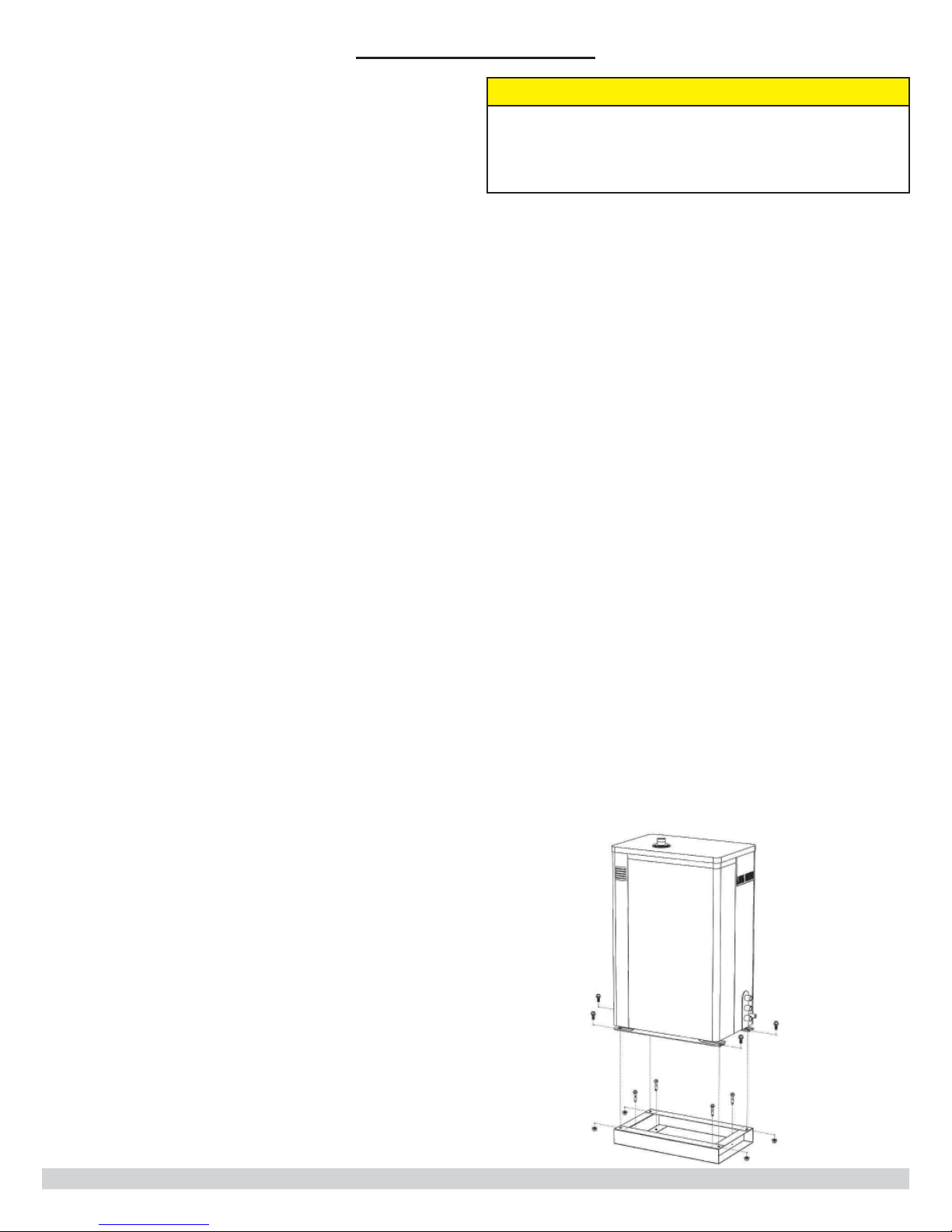
Install MCHP unit base as specifi ed in HONDA MCHP, •
Model YM2Z, Installation Manual and Owner’s Manual
as summarized below and Figure 8-1.
Place base on concrete fl oor and level.•
Mark anchor bolt locations on concrete fl oor.•
PLUS
System:
freewatt PLUS
freewatt PLUS
freewatt PLUS
System is
Boiler
system
CAUTION
Penetration or modifi cations of MCHP cabinet will
result in potential electrical or fi re hazard. Do
not attach controls, wire, piping, conduit or other
hardware to MCHP unit.
Place HONDA MCHP on base and secure MCHP unit to •
base with supplied hardware after base installed. See
Figure 8-1.
Determine location of Hydronic HI Module enclosure. •
Mount enclosure on solid wall or partition. Recommend
enclosure be located close to HONDA MCHP. HI module
may be mounted up to 10 feet away from HONDA
MCHP unit. Locate enclosure with installation and
service accessibility in mind.
Hydronic HI Module bottom should be installed at •
height of 32” to 42” above fl oor elevation where
base of HONDA MCHP is installed.
Ensure top of Hydronic Hybrid Integration (HI) •
module is mounted above Honda MCHP’s top cover.
HI Module bottom should not be above MCHP top.
Hydronic piping between HI module and primary •
hydronic loop manifold should not exceed 40 feet.
Piping and circulator should be designed for water
fl ow rate of 4gpm. HI module heat exchanger
pressure drop is approximately 1 psi.
Position enclosure, check for level, mark mounting •
holes.
Start screws (#10 ,4 each, fi eld source) for keyhole •
type mounting holes in upper corner(s). Tighten
screws down to about 1/8” (3mm) from surface.
Hang enclosure on screws, position enclosure and •
start bottom screws.
Tighten all screws.•
Drill hole diameters in concrete for anchor bolts •
per manufacturer’s installation instructions. If
obstruction is hit, move base and re-drill.
Attach base to anchor bolts with supplied hardware.•
Locate washers between MCHP and base if unit •
needs to be shimmed level.
Orientation of bolt & nut is important. Bolt must be •
installed from top with nut on bottom. Use nuts and
bolts supplied in installation kit. Do not use shipping
bolts which attach MCHP to shipping pallet.
Do not make penetrations or drill holes in MCHP unit •
cabinet.
Figure 5-1 MCHP Base Installation
22
Page 23
8 - PLACING THE SYSTEM
8.3 freewatt PLUS
Place equipment in proper locations. •
Confi gure system piping to connect boiler and HONDA •
MCHP to distribution piping.
Hydronic •
modifi ed primary-secondary, allowing heat from MHCP
unit be injected into return piping upstream from
freewatt PLUS
return water be delivered to MCHP unit’s hydronic
hybrid integration (HI) module.
freewatt PLUS
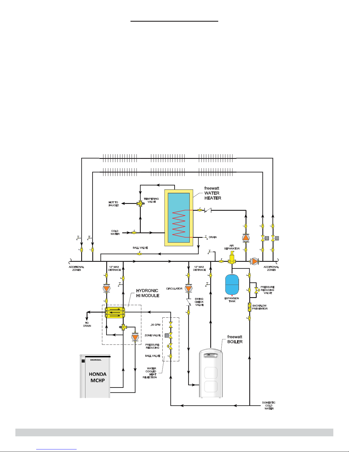
Figure 8-2 Hydronic
System Piping
piping confi guration is
boiler. Confi guration ensures coldest
Freewatt PLUS
System Distribution Piping Schematic with Zone Valves and
Priority DHW Pump
Figure 8-2 shows •
schematic for system zoned with zone valves for
heating zones and priority pump for indirect water
heater zone. Confi guration of heating zones, boiler
and MCHP heat sources shown is mandatory for proper
operation of
See piping schematics in Section 17 for circulator zoned •
systems, valve zoned systems and systems with air
handlers.
freewatt PLUS
freewatt PLUS
distribution piping
System.
23
Page 24
8 - PLACING THE SYSTEM
8.4 Design Tips
Install bottom of Hydronic HI Module at height of •
32” to 42” above fl oor elevation where HONDA MCHP
installed.
Maximum 10ft. length of ½” Onix coolant tubing •
connecting Hydronic HI module and MCHP.
Install mixing valve if indirect hot water tank is •
installed. Mixing valve will provide anti-scalding
protection and allow for summer operation of MCHP
unit. Review installation requirements supplied with
Indirect Water Tank.
8.5 Near Boiler Piping
Do not install Copper piping directly into aluminum •
boiler casting due to galvanic corrosion between
dissimilar metals. Two (2) dielectric isolation unions
shipped loose in boiler parts bag. Install dielectric
isolation unions at boiler supply and return line. Use of
dielectric unions is required.
furnished with iron piping where necessary for supply
and return connections.
Confi gure near boiler piping in accordance with •
freewatt PLUS
Maintenance Manual. Overall confi guration with MCHP
unit and heated zones must be in conformance with
Figure 8-2.
Boiler’s Installation, Operation and
freewatt PLUS
boiler
NOTICE
Use only long life coolant supplied with
PLUS
System. Use of any other coolant will void
warranty.
System will not operate properly and permanent
damage to Hydronic HI Module or HONDA MCHP
may occur if followings steps are not followed.
Following steps are required to install long life coolant (LLC)
tubing between Hydronic HI module and HONDA MCHP.
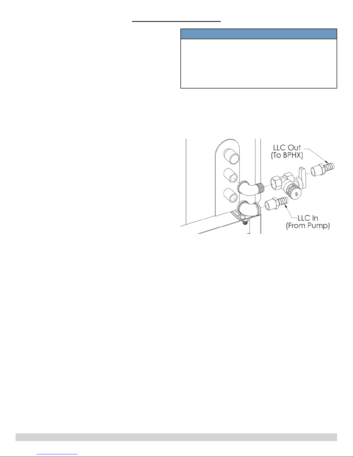
Figure 8-3 MCHP Coolant Loop Drain Tee (LLCLong Life Coolant Supplied with System)
freewatt
freewatt PLUS
• Boiler provided with 1 ¼” NPT return
and supply piping connections shown in Figure 2-2.
freewatt PLUS
• Boiler Installation, Operation and
Maintenance Manual includes directions on distribution
system requirements, including expansion tank, makeup water, air separator, air vent and condensate drain
piping (pump).
Install 1 ¼” ball valves on supply and return legs of •
boiler connection to allow for servicing of boiler or
circulators.
8.6 Honda MCHP & Hydronic HI Module
Install MCHP near piping in accordance with HONDA •
MCHP installation manual and instructions found in this
section.
Typical piping confi guration is shown in Figure 2-1, •
shows MCHP connecting to hydronic HI Module.
Hydronic HI Module connects to hydronic water
distribution system.
Place hydronic HI module in location allowing MCHP to •
connect with maximum 10 feet of ½” Onix tubing, while
also located vertically above MCHP unit (32” to 42”
above MCHP’s base level).
Onix tubing used to isolate vibrations from Honda •
MCHP unit and is provided with installation kit.
8.7 HI Module coolant tubing:
Prepare rear connections (LLC In and LLC Out) of •
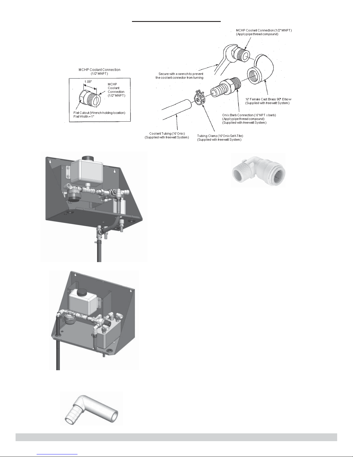
MCHP unit with pipe thread sealant. Install ½” NPT
brass street elbow onto drain fi tting before installing
1/2” NPT street elbow onto MCHP unit’s 1/2” MNPT LLC
Out fi tting. Install other 1/2” NPT brass elbow onto
MCHP unit’s LLC In fi tting. Install 1/2” NPT x 1/2” barb
fi ttings into drain fi tting and 1/2” NPT elbow. Point
fi ttings in direction of front of hydronic HI Module.
Figures 8-3, 8-4 and 8-5.
Long Life Coolant • Out Tubing Installation [MCHP to
BPHX; Figure 8-5]:
Attach supplied 1/2” brass Tee to threaded heat •
exchanger fi tting located on bottom of HI Module as
shown. (Apply pipe thread compound)
Attach supplied 1/2” NPT x barb fi ttings to remaining •
threads on brass Tee. (Apply pipe thread compound)
Attach supplied 12.5” length of tubing to front of •
brass tee. Route cable through sheet metal as
shown. Attach stackable hose barb fi tting and insert
into HOT side of mixing valve. Secure fi ttings using
tubing clamps.
Install Onix™ tubing from top rear LLC connection •
on MCHP, to hose barb on bottom of tee. Secure
24
Page 25
8 - PLACING THE SYSTEM
Figure 8-4 MCHP Coolant Line Installation Instructions
Figure 8-5 LLC Out Connection to HHI Module
(BPHX)
Figure 8-6 LLC In Connection to Pump
Figure 8-8 Female Swivel Fitting (NPT by IPS)
using tubing clamp.
Long Life Coolant • In Tubing Installation: [Pump to
MCHP; Figure 8-6]
Cut section of Onix Tubing to extend from MCHP •
unit’s lower Coolant connection to coolant pump in
HI Module.
Install barbed end of elbow (barb x IPS) fi tting into •
open tube end of tubing and secure with SelfTite
clamp. Figures 8-7 and 8-8
Route tubing through hole in bottom of Hydronic HI •
Module.
Insert IPS end of same elbow (barb x IPS) fi tting •
into female IPS swivel fi tting (Figure 8-7 and 8-8)
on coolant pump and secure with collet clip supplied
with female swivel fi tting.
Figure 8-7 - Hose Barb by IPS Elbow Fitting
Route tubing to rear of MCHP (if necessary through •
open channel in front of MCHP base) and cut to
length.
Install tubing onto lower brass hose barb fi tting (LLC •
In) and secure SelfTite clamp onto tubing.
Use only Watts Radiant brass barb fi ttings with Onix tubing
supplied with
fi ttings are made to different dimensions and tolerances,
which may result in leaks.
freewatt PLUS
System. Off-the-shelf brass
25
Page 26
8- PLACING THE SYSTEM
8.8 HHI Module to Distribution Manifold
Follow industry standards when installing distribution •
manifold.
Install MCHP hydronic pump below manifold to prevent •
circulator from air locking.
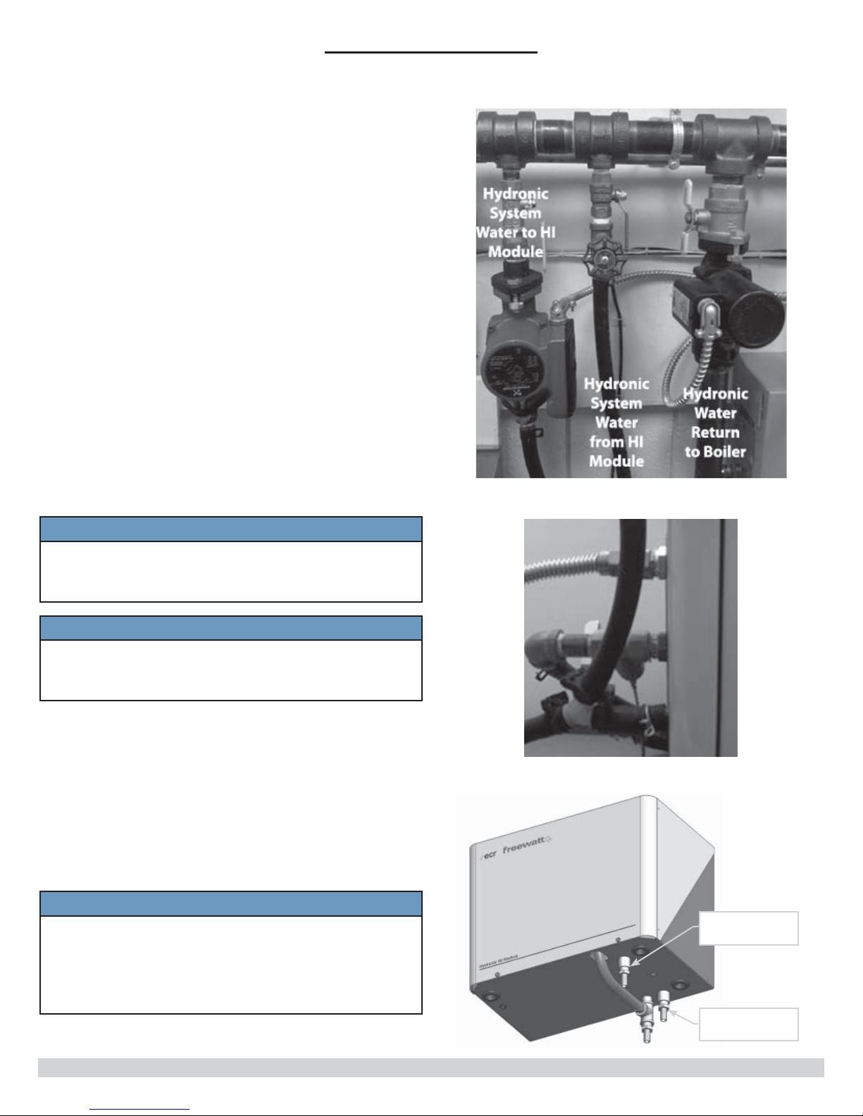
Size tubing or piping connecting Hybrid HI module •
with distribution manifold ½” NPT or larger to provide
adequate fl ow for transfer of heat from MCHP’s coolant
into hydronic water.
Pump shall provide fl ow of at least 4 gpm to brazed •
plate heat exchanger (~1 psi Pressure Drop) in
Hydronic HI Module. Grundfos SuperBrute Pump
(UPS1558FC) is suggested.
See Figure 8-9 design example of piping.•
Installation•
Attach two supplied 1/2” NPT X barb fi ttings to A.
threads on bottom of heat exchanger per Figure
8-11. Apply pipe thread compound.
Attach Onix tubing to barbs securing with Selftite B.
clamps.
8.9 HHI Module Heat Rejection System
Connections
Figure 8-9 HI Module to Distribution Manifold
Piping
Figure 8-10 Condensate Lines
NOTICE
Follow these steps to ensure proper system
operation and prevent permanent damage to
Hydronic HI Module or Honda MCHP.
NOTICE
Follow detailed instructions provided with heat
rejection accessory kit to construct heat rejection
piping loop.
Following steps are required to connect heat rejection system to Hydronic HI Module for Heat Rejection cooling.
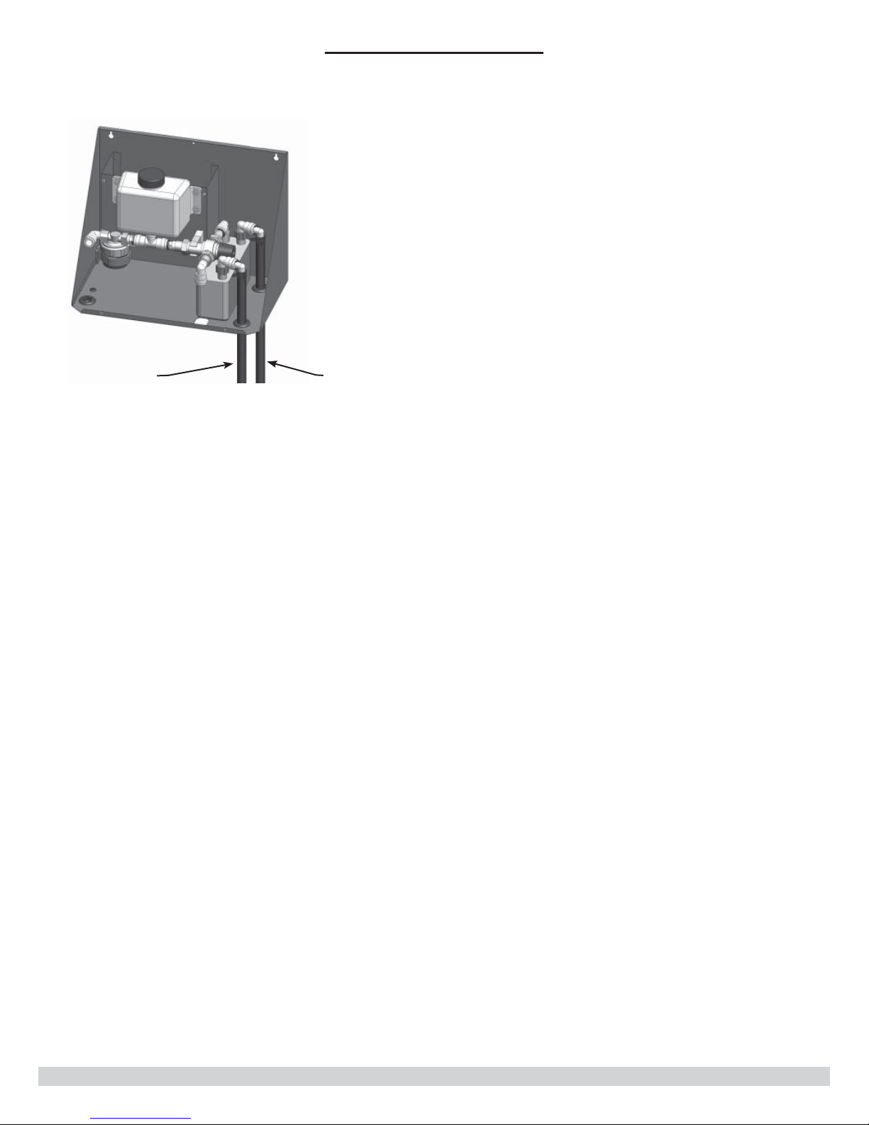
Install pipe or tubing from supplied heat rejection loop •
to BPHX. Ensure counter fl ow between heat rejection
fl uid and MCHP Coolant. See Figure 8-12.
Install pipe or tubing from outlet of BPHX to heat rejec-•
tion loop.
Figure 8-11 Hydronic freewatt® PLUS HI
Module
8.10 Condensate Drain Piping
NOTICE
Boiler and MCHP’s drain trap assembly must be
fi lled with water before operating system. Dry trap
may cause pressure switches to behave erratically,
preventing boiler from operating normally, or cause
exhaust products to enter building space.
From
Hydronic Loop
To
Hydronic Loop
26
Page 27
8 - PLACING THE SYSTEM
Figure 8-12 Heat Rejection Connections to HHI
Module (BPHX)
Heat Rejection
OUT
Heat Rejection
IN
freewatt PLUS
• boiler and MCHP unit will produce
condensate at rates up to 2 ½ US quarts per hour.
Make provisions to drain condensate away from both
boiler and MCHP to ensure proper operation. Boiler
is supplied with factory-installed drain trap assembly
with ½” dia. Sch. 40 PVC connection.
Install MCHP condensate line directly into condensate •
pump, located directly behind MCHP unit, if fl oor drain
is not available. Condensate line should have “Y
connector” to ensure tubing is open to atmosphere,
removing chance for air lock in line. Figure 8-10.
Route boiler’s condensate line behind MCHP unit and
install directly into condensate pump.
Supplied boiler condensate vent drain T must be used.•
Do not make any additional electrical connections •
freewatt PLUS
within
Separate junction box and receptacle should be
provided if 120 VAC power is required for condensate
pump.
Review installation instructions for boiler and HONDA •
MCHP to ensure a proper installation.
System for 120 VAC power.
8.11 Onix Clamps
Do not use screw gun or wrench to tighten TorqueTite •
clamps.
Safety glasses must be worn when installing SelfTite •
Clamps.
Minimum bending radius of ½” Onix tubing is 4”.•
Onix requires special Torque-Tite or Self-Tite •
mechanical clamps, designed for higher temperature
and burst pressure ratings.
Self-Tite clamps are supplied with •
System.
TorqueTite clamps are heavy-duty screw-type, •
wide-band, stainless steel clamps. In. per lb. torque
wrench is required to install. Tightened each clamp
according to proper torque setting for size of clamp
used. Torque settings are listed on instruction
sheet supplied with clamps.
Do not over tighten TorqueTite clamp. •
Overtightening may cause long-term damage to
Onix tubing and/or to clamp itself.
SelfTite Clamps are chrome-vanadium, constant •
tension clamps. Watts Radiant recommends using
SqueezeTite pliers to properly open and install clamps.
freewatt PLUS
Do not allow clamp to fl atten while being held open. •
Flattened clamps will not fi t properly over Onix and
barb assembly.
27
Page 28
8 - PLACING THE SYSTEM
All Onix and brass fi tting surfaces must be clean and •
dry before making connection.
Avoid making connections or splices in inaccessible •
locations.
Repairing Onix having been in service in •
PLUS
System requires special attention. Any residual
amounts of
Onix tube must be removed. Use an alcohol swab or
pad to remove residue(s), allow tube to dry prior to
connection.
freewatt PLUS
long life coolant inside
freewatt
NOTICE
Do not solder near, or overheat, any Onix
connections. Extreme temperatures associated with
soldering may seriously damage Onix and will void
warranty.
8.12 Confi guration of Heating Zones and
Controls
Hydronic •
variety of heating loads served by conventional, multizone hydronic heating systems. Including base-board
radiation, radiant fl oor heating, domestic hot water
via indirect storage tank, powered convective heaters,
hydro coils, and others.
freewatt PLUS
System may be applied to
Expand ECR control using appropriate ECR •
expansion relay controls if additional zones are
needed.
Two air handlers with circulators can be accommodated •
through use ECR ARH-3 control.
One air handler must be “Zone 2 - Smart Zone”. •
If additional zones are needed, expand ECR control •
using appropriate ECR expansion relay controls.
Select “Smart Zone” as zone with largest heating •
demand (but not domestic hot water zone). This
would normally be largest space in heating zone on fi rst
fl oor of two story home.
produce best electric power generation benefi t if Smart
Zone represents 25% of total home heating load. If
there is no single large zone in existing distribution
system, but many small zones, consider combining
zones to achieve desired heat load for the Smart Zone.
Installations of Hydronic
use of AR-822-II for operation of circulator that provides
hydronic water fl ow to HI Module.
freewatt PLUS
freewatt PLUS
System will
System require
Use correct ECR zone control accessory kit, ordered •
separately, for type of zoning to be applied with
hydronic
freewatt smart zone communicating thermostat,
AR822-II pump relay for MCHP hydronic loop pump,
and appropriate zone control relay as follows:
Thermostats for up to six zones, must be wired through •
freewatt PLUS
Required ECR heating zone relay controls for use with •
pumped zoned systems (ARM-6P) and valve zone
systems (AZ-6CP) can accommodate total of 6 zones.
freewatt PLUS
Use Zone Pump Zone Control Accessory Kit which •
includes ARM-6P for pump zoned systems,
Use Zone Valve Zone Control Accessory Kit which •
includes AZ-6CP for valve zoned systems,
Use Hydro-Air Zone Control Accessory Kit which •
includes ARH-3 for distribution systems with air
handlers.
One zone of six zones must designated “Zone 2 - •
Smart Zone”.
Zone 1 is used to accommodate indirect water •
heater having its own dedicated circulation pump.
Control Module.
System. Kit includes
28
Page 29
9 - EXHAUST GAS LEAK SENSOR
9.1 EGLS Introduction
Exhaust Gas Leak Sensor System in addition to •
separate, independently installed and operating UL
approved Carbon Monoxide Detector having audible
alarm.
Install both Exhaust Gas Leak Sensor (supplied with •
freewatt PLUS
Monoxide Detector (not supplied with
PLUS
).
freewatt PLUS
• System and
Gas Leak Sensor do not provide audible alarms for
protection of building inhabitants from potential high
CO hazards.
Function of •
System is to automatically stop operation of MCHP unit
in event it detects potentially hazardous level of carbon
monoxide in vicinity of MCHP unit.
freewatt PLUS
• System Exhaust Gas Leak Sensor
System uses Macurco CO Detector con nected directly
to Honda MCHP Unit. Read following installation
instructions:
Read and understand installation and operation •
manual for Macurco CO Detector part of Exhaust Gas
Leak Sensor System.
Install Macurco CO Detector per manufacturer’s •
instructions in close proximity of HONDA MCHP unit.
) and audible UL approved Carbon
freewatt
freewatt PLUS
freewatt PLUS
Exhaust Gas Leak Sensor
Exhaust
Figure 9-1 shows connections to Exhaust Gas Leak •
Sensor. Exhaust Gas Sensor will automatically stop
operation of MCHP unit upon detection of potentially
dangerous levels of carbon monoxide gas regardless of
source of carbon monoxide gas.
9.2 Preparation
Following items must be installed before Exhaust Gas Leak
Sensor can be installed:
Boiler, Control Module & Hydronic HI Module•
Honda MCHP Unit•
Thermostat•
!
WARNING
Exhaust Gas Leak Sensor does not fulfi ll
independent CO detector and audible alarm
requirement of freewatt PLUS System.
freewatt PLUS System requires separate CO
alarm for protection of building inhabitants.
Separate freewatt PLUS System installation
requirement is fulfi lled by complying with State
of Massachusetts’s CO detector and alarm
requirements. Your state or local jurisdiction may
have additional requirements regarding carbon
monoxide detectors and alarms.
Install four-wire cable from HONDA MCHP to •
Macurco CO Detector.
Verify cable properly secured (Maximum interval: •
every 3 ft.)
Exhaust Gas Leak Sensor (EGLS) monitors integrity of •
MCHP unit’s combustion system shutting down MCHP
unit if potentially unsafe conditions are detected.
Monitors carbon monoxide level in air space •
near MCHP unit. EGLS is independent of, and
separate from, audible CO alarming system that
must be installed with
compliance with best practices for all fuel-fi red
central heating equipment.
!
WARNING
freewatt PLUS Exhaust Leak Gas Sensor does
freewatt PLUS
System in
not fulfi ll State of Massachusetts’s CO detector
and alarm requirement. Exhaust Gas Leak Sensor
does not provide an audible alarm for potentially
hazardous CO levels.
Exhaust Gas Leak Sensor is supplied with Hydronic •
freewatt PLUS
in close proximity of HONDA MCHP unit.
System and is intended for installation
9.3 Installation
Exhaust Gas Leak Sensor is connected to HONDA MCHP
unit using four conductor stranded insulated cable supplied
by Honda. Follow installation instructions below to ensure
proper operation of Exhaust Gas Leak Sensor:
Honda MCHP Connection
4-pin cable connector to the HONDA MCHP for the •
Exhaust Gas Leak Sensor is factory-supplied and fi eld
installed. The HONDA MCHP installation kit includes an
electrical schematic for the wiring details.
See HONDA MCHP Installation manual for the •
connections to the HONDA MCHP and for any servicing
or troubleshooting.
Exhaust Gas Leak Sensor Connections
Field install cable connection to Exhaust Gas Leak •
Sensor after installation of sensor. Figure 9-1 shows
fi eld connections of supplied cable to Exhaust Gas Leak
Sensor.
See MCHP Installation manual for connections to •
HONDA MCHP for servicing or troubleshooting.
Field install jumper wire between second terminal (F) •
and fourth terminal (N.C.). May need to install another
Jumper between COM and B terminals instead of using
crimp.
29
Page 30
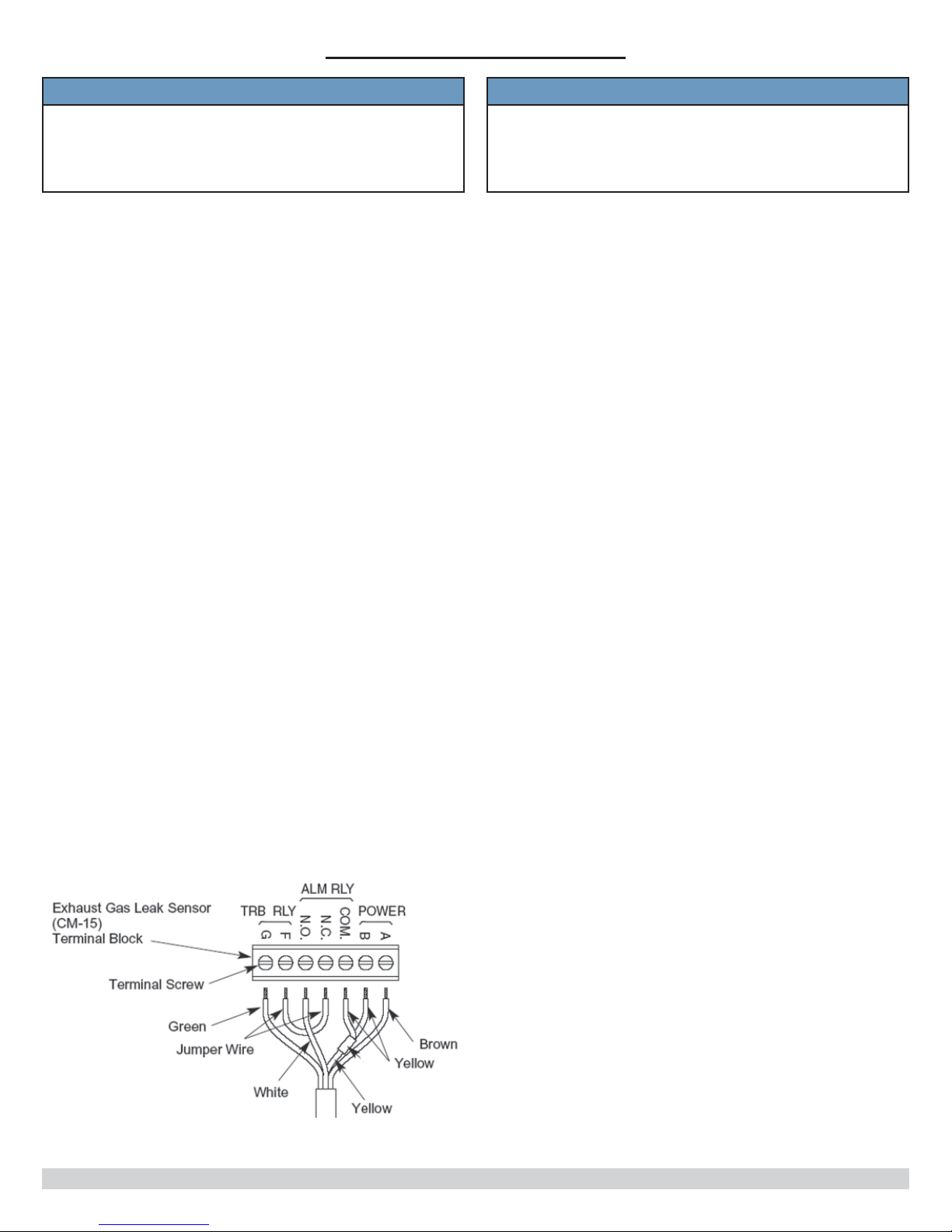
9 - EXHAUST GAS LEAK SENSOR
NOTICE
Exhaust Gas Sensor’s cable connections must be
installed properly or Hydronic
System will not initialize and not operate (ERROR –
14 or 15 Flashes).
For more instructions on connecting Exhaust Gas Leak
Sensor SEE MCHP IOM.
9.4 Test Procedure
Test Exhaust Gas Leak Sensor to ensure proper operation
before commissioning system. Use Exhaust Gas Leak
Sensor test button in accordance with procedure below.
Procedure will stop MCHP unit. See “
Section 16
Disconnect
1. freewatt PLUS
Temporarily disconnect LAN (local area network) cable
from side of
LAN cable where it plugs into home’s network.
Power is supplied to Exhaust Gas Leak Sensor by
2.
MCHP. MCHP must be operating during testing of
Exhaust Gas Leak Sensor. Turn thermostat up until
MCHP operates, if MCHP is not operating.
Wait for LED on Macurco CO Detector to begin glowing
3.
green. Press button on Exhaust Gas Leak Sensor
labeled “Push Here to Test or Reset” for 6 seconds,
when LED on Macurco CO Detector is glowing green
continuously. This should cause
System error condition.
if MCHP unit does not stop,.
freewatt
Control module or disconnect
freewatt PLUS
Troubleshooting”
System from Internet.
freewatt PLUS
NOTICE
LED indicator on Exhaust Gas Sensor must be solid
green. Sensor is initializing if it is fl ashing red
and green. Wait 3 minutes until LED is solid green
before proceeding.
Confi rm HONDA MCHP unit has stopped operating,
4.
and red “Service Required” LED on
System’s front panel is blinking error code “16”, and
yellow “Bypass” LED is on.
Clear error condition. Turn OFF 120 VAC
5. freewatt
PLUS
MCHP Service Switch.
Reconnect LAN cable to
6. freewatt PLUS
Turn power ON to HONDA MCHP 240 VAC Service
7.
Switch, turn ON
Service Switch, to return system to normal operation.
Exhaust Gas Sensor must be replaced every 5 years with
identical unit, installed by qualifi ed and properly trained
service personnel.
freewatt PLUS
required LED will indicate fault by fl ashing 16 times if you
push test button on
Sensor.
Fault message will be transmitted to
service center if your system is connected to internet.
Clear fault condition to restore MCHP operation. Shut off
electrical power to
power to reset system using power switch on
Control module to clear fault.
System Service Switch and 240 VAC Honda
freewatt PLUS
generator will stop and red service
freewatt PLUS
freewatt PLUS
freewatt PLUS
System.
System 120 VAC
Exhaust Gas Leak
freewatt PLUS
System and restore
freewatt
Figure 9-1 Exhaust Gas Leak Sensor
Connections
30
Page 31
10 - COMBUSTION AIR AND VENT PIPE
!
WARNING
Read, understand and follow all instructions. Failure
to properly vent or supply combustion air to boiler
can cause carbon monoxide poisoning, or an
explosion or fi re, personal injury or loss of life.
10.1 General Considerations
Perform tasks outlined in Section 5 of •
boiler Installation, Operation and Maintenance Manual,
section “Removal of Existing Boiler from Common Vent
System” if system will be replacing Category I type
boiler connected to chimney serving other appliances.
Vent installations shall be in accordance with ANSI •
Z223.1/NFPA 54, CSA-B149.1 and B149.2, or authority
having jurisdiction.
Provisions for combustion and ventilation air shall be •
in accordance ANSI Z223.1/NFPA 54, CSA-B149.1 and
B149.2, or authority having jurisdiction.
Hydronic •
components requiring combustion air and discharge of
combustion products.
freewatt PLUS
Boiler component requires dedicated direct vent •
system. All air for boiler’s combustion is taken
directly from outdoors through combustion air intake
pipe. All combustion products are discharged to
outdoors through vent pipe.
Honda MCHP takes combustion air from interior •
open space and all combustion products are
discharged to outdoors through vent pipe.
System has two separate
freewatt PLUS
Combustion air pipe and vent connections on boiler are •
2” pipe size. Installed combustion air pipe and vents for
boiler must be 3” size and, 2” to 3” pipe coupling must
be used at boiler connections. MCHP vent connection
size is 2”. 2” or 1-1/2” vent size is permitted. Refer
to
freewatt PLUS
Maintenance Manual and MCHP IOM for specifi c venting
instructions.
Exhaust transition from 2” pipe to 3” pipe must •
be made in vertical run. Transition pieces are not
included. (See boiler installation manual for more
details.)
Boiler Installation, Operation and
10.2 Combustion and Vent Piping Length
Refer to direct vent and non-direct combustion air and vent
sections outlined in installation guides for boiler and Honda
MCHP for specifi c installation procedures and specifi cations.
10.3 Installation
Refer to direct vent and non-direct combustion air and •
vent sections outlined in installation guides for boiler
and HONDA MCHP for specifi c installation procedures
and specifi cations. General guidelines for air intake
and vent piping are found in
Installation, Operation and Maintenance
Manual.
Use of periscopes on air intake and venting are allowed. •
Insulate periscopes with proper weather-resistant pipe
insulation if extend over 24” in length, straight length.
FW95M-200 Boiler
See installation instructions in boiler and HONDA MCHP •
manuals for combustion air and vent pipe roof and
sidewall termination (Roof termination is preferred).
Combustion air and vent pipes for
Boiler must terminate together in same atmospheric
pressure zone as shown. Boiler and MCHP exhaust
vents need not be in same general location on exterior
of building. Construction through which vent and air
intake pipes may be installed is maximum 24 inches,
minimum ¼” thickness.
Combustion air and vent pipe fi ttings must conform •
to American National Standards Institute (ANSI) and
American Society for Testing and Materials (ASTM)
D1784 (schedule 40 CPVC), D1785 (schedule 40 PVC),
D2665 (PVC-DWV), D2241 (SDR-21 and SDR-26 PVC),
D2661 (ABS-DWV), or F628 (schedule 40 ABS). Pipe
cement and primer must conform to ASTM standards
D2564 (PVC) or D2235 (ABS). In Canada construct
all combustion air and vent pipes for system of CSA or
ULC certifi ed schedule-40 CPVC, schedule-40 PVC, PVC-
DWV or ABS-DWV pipe and pipe cement. SDR pipe is
not approved in CANADA.
freewatt PLUS
10.4 freewatt PLUS
and Venting
Combustion air and venting installation procedures and
specifi cations are based on installation specifi cations of
boiler and MCHP. Installers are required to follow specifi c
installation requirements found in boiler and MCHP
installation manuals, following guidelines are taken from
these manuals.
10.5 United States Direct Vent System
Requirements
Boiler direct vent exhaust shall be installed in United States
in accordance with following requirements. Allowable
direct vent intake and exhaust piping lengths for boiler
are found in FW95M-200 Boiler Installation, Operation and
Maintenance Manual.
System Combustion Air
31
Page 32
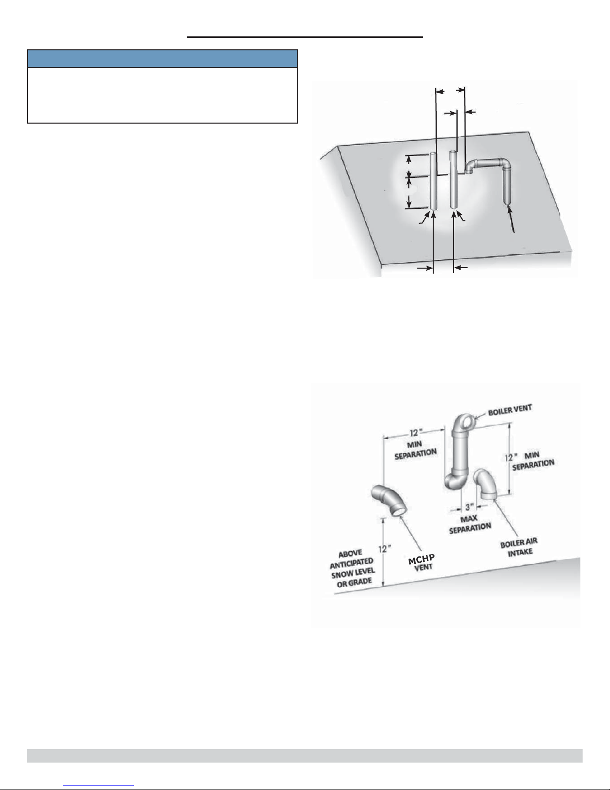
10 - COMBUSTION AIR AND VENT PIPE
NOTICE
Install boiler per Direct Venting requirements.
Install MCHP per Non-Direct Venting Requirements.
Distinction is noted to ensure proper location of vent
terminations.
Clearance from bottom of termination to grade shall •
be 12” or increased to maintain 12” above anticipated
accumulated snow level.
Vent shall not terminate over public walkways or over •
area where condensate or vapor could create nuisance
or hazard.
Vent termination shall be installed at least 1 foot from •
any opening through which fl ue gases could enter
building.
Vent termination shall have minimum horizontal •
clearance of 4 feet from electric meters, gas meters,
regulators and relief equipment.
Locate vent terminal 3 feet horizontally from vent •
of any side wall vented fuel gas appliance or clothes
dryer, except in case of hydronic
System where boiler and MCHP vents may be located
with respect to each other per Figures 10-1 or 10-2.
freewatt PLUS
Figure 10-1
Min. Separation
MCHP Vent
12”
3” Max Separation
8”
7”
Boiler Vent
Boiler Air
Intake
3” Min.
Figure 10-2
10.6 United States Non-Direct Vent System
Requirements
Non-direct vent exhaust for MCHP shall be installed in
United States accordance with following requirements; nondirect vent exhaust piping lengths for MCHP are found in
Honda MCHP Installation Manual:
Clearance from bottom of termination to grade shall •
be 12” or increased to maintain 12” above anticipated
accumulated snow level.
Vent shall not terminate over public walkways or over •
area where condensate or vapor could create nuisance
or hazard.
Vent termination shall be installed at least 4 feet below, •
4 feet horizontally from, or 1 foot above any door,
window, soffi t, under eave vent or gravity air inlet to
the building.
Vent termination shall have minimum horizontal •
clearance of 4 feet from electric meters, gas meters,
regulators and relief equipment.
Locate vent terminal 3 feet horizontally from vent •
of any side wall vented fuel gas appliance or clothes
dryer, except in case of hydronic
system
where boiler and MCHP vents may be located
with respect to each other per fi gures 10-1 or 10-2.
freewatt Plus
32
Page 33
11 - GAS SUPPLY PIPING
CAUTION
Units cannot operate properly or safely using fuels
outside normal commercial standards. Connect
boiler and HONDA MCHP units only to gas supplied
by commercial utility or supplier. Private gas
wells do not generally provide gas with consistent,
uniform and predictable heating values and
densities. Many non-commercial wells contain
impurities such as sulphur, which may damage
furnace or HONDA MCHP.
11.1 Check Gas Supply
Gas pipe to boiler must be correct size for length of run •
and for total BTU per hour input of all gas utilization
equipment connected to piping. See Tables in boiler
and HONDA MCHP installation manuals for proper
size. Verify gas line complies with authority having
jurisdiction.
freewatt PLUS
• Boiler and MCHP units’ individual
shutoff valves must be disconnected from gas supply
piping system during any pressure testing of system at
test pressures in excess of ½ psig (3.5 kPa).
Table 11-1 Gas Supply Pressures
Gas tyoe
Natural 4” 7” 10”
Propane 10” 12” 14”
Consult boiler and HONDA MCHP installation procedures for
leak testing and purging gas lines.
Minimum
(in. w.c.)
11.2 Gas Piping
Consult boiler and HONDA MCHP installation procedures for
specifi c instructions regarding gas piping.
Nominal
(in. w.c.)
Maximum
(in. w.c.)
freewatt PLUS
• Boiler and MCHP unit system must
be isolated from gas supply piping system by closing
respective individual manual shutoff valves during any
pressure testing of gas supply piping system at test
pressures less than or equal to ½ psig (3.5 kPa).
Recommend line pressure be within minimum and •
maximum values in Table 11-1 for proper operation of
system.
33
Page 34
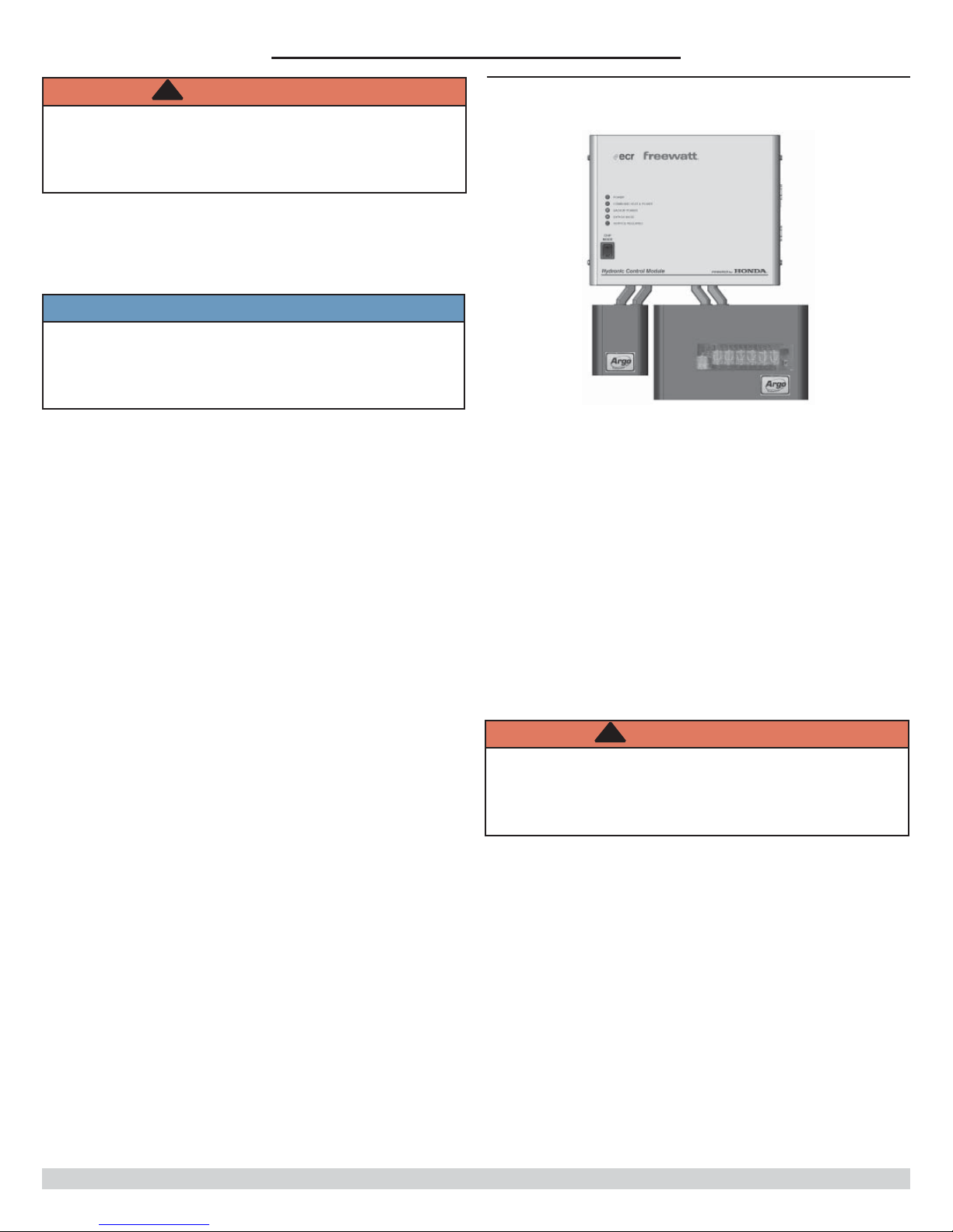
12 - ELECTRICAL WIRING & CONNECTIONS
!
WARNING
Electric shock hazard. For your safety, turn off electrical power supply at service panel before making
any electrical connections. Failure to do so can cause
severe personal injury or death.
12.1 Codes
Installation must comply with National Electrical Code, authority having jurisdiction, and in Canada, with CSA C22.1 Canadian
Electrical Code and authority having jurisdiction.
NOTICE
Wiring shall be N.E.C Class 1. Use only type 105°C
wire or equivalent if original boiler wiring must be
replaced. System shall be electrically grounded as
required by National Electric Code ANSI/NFPA 70.
12.2 Line Voltage Connections
System installation must include :
120 VAC dedicated circuit (15 amp) to Boiler, control •
module, circulator pumps and relay switches.
120 VAC dedicated circuit will extend up to •
Transfer Switch.
240 VAC dedicated circuit (2 pole; 15 amp) to HONDA MCHP •
unit.
240 VAC dedicated circuit shall have serviceman’s
•
switch fi eld installed near Honda MCHP on circuit
between main service panel and freewatt Transfer
Switch.
freewatt
Figure 12-1 Typical freewatt PLUS Control
Module Confi guration
Mounting 2 ft. wide x 4 ft. high sheet of plywood provides •
mounting surface for control module, relay switches and HHI
module. Unit may be mounted up to 20 feet away. Locate
enclosure with installation and service accessibility in mind.
Position control module enclosure above ECR relay •
switches, place enclosure on relay switch modules with
four ½” off set nipples, level, and mark mounting holes.
Start screws, #10, 4 each (fi eld sourced) for keyhole type •
mounting holes in upper corner(s). Tighten screws down
to 1/8” (3mm) from surface.
Hang enclosure on screws, level enclosure and tighten •
screws.
Install four nuts on ½” offset nipples to secure enclosure •
to relay switch modules. Figure 12-1 .
9.3 Line Voltage Wiring Specifi cations
240 VAC Wiring: All wiring must conform to National •
Electric Code and authority having jurisdiction. Wiring
must be N.E.C. Class 1. In Canada, C.S.A. C22.1
Cana dian Electrical Code Part 1 and authority having
jurisdiction. Wiring must be C.S.A. C22.1 C.E.C. Part 1.
120 VAC Wiring: All wiring must conform to National •
Electric Code and authority having jurisdiction. Wiring
must be N.E.C. Class 1. In Canada, C.S.A. C22.1
Canadian Electrical Code Part 1 authority having
jurisdiction must be followed. Wiring must be C.S.A.
C22.1 C.E.C. Part 1.
12.4 freewatt Control Module Installation
Mount module’s enclosure on solid wall or partition after •
determining location of
enclosure be located close to
Honda MCHP and HI Module, within reach of supplied, preterminated cable.
freewatt
module. Recommend
freewatt PLUS
Boiler,
!
WARNING
Electric shock hazard. Do not route un-switched
line-powered cables or wires through freewatt PLUS
System. F ailure to do so can cause sev ere personal
injury or death.
Recommend no additional electrical connections be made
within
power is required for condensate pump, separate junction
box and receptacle should be provided.
120 VAC dedicated circuit shall conform to NEC and use as
minimum 3-conductor, 14 Ga. Cable.
freewatt
Control module for line power. If line
12.5 Wiring Instructions
Provide and install non-fused disconnect or 120VAC •
service switch ( 15 amp recommended) as required by
authority having jurisdiction.
Route 120 VAC power wiring from service switch to boiler’s •
line voltage terminal strip on boiler control panel as outlined
in
freewatt PLUS
Maintenance Manual. See Location 8 in Figure 12-2.
Boiler Installation, Operation and
34
Page 35
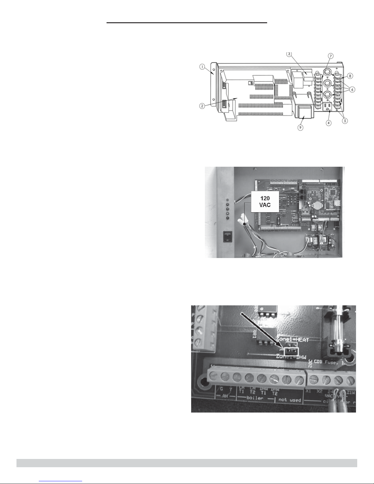
12 - ELECTRICAL WIRING & CONNECTIONS
Route 120 VAC power wiring from service switch to ECR •
AR822-II and attach to 120 VAC power terminals.
Route 120 VAC power wiring from junction / switch •
box to ECR ARM-6P (or AZ-6CP or ARH-3). Wiring can
be routed through ½” offset nipple connector and into
control module enclosure. Connect 120 VAC power
wiring to 12 VDC power supply’s pig tail in control
module using wire nuts, attach ground wire to control
module enclosure grounding screw located inside
bottom of enclosure. Figure 12-3.
Wire control module to zone relay control and AR822-II •
following appropriate
and line voltage electrical schematics.
Wire circulators and MCHP’s hydronic pump to zone relay •
control and AR822-II following instructions found in their
installation manuals and
schematics.
Connect MCHP Coolant Pump’s 24VDC power cable to system •
controller.
Connect 24 VAC circuits between boiler control and •
freewatt
schematic.
Confi gure jumper on control module circuit board (Figure •
12-4) for set-up of hydronic system water heating and
space heating zones. Install jumper on DHW pins if zone 1 is
connected to aquastat in indirect water tank. Install jumper
on HEAT pins If zone 1 is connected to thermostat for space
heating. Zone 1 input on the control module must be used
for indirect water heater if indirect water heater is used with
freewatt PLUS
Connect Coolant Pump in HI Module to Control Module J04 •
connector using furnished coolant pump cable.
Control Module per applicable electrical
freewatt PLUS
freewatt PLUS
System.
System low voltage
System electrical
12.6 ECR Zone Relay Controls
Install appropriate ECR Zone Relay Control for temperature •
control of different heating zones and accommodation of
indirect water heater (if used). Refer to Electric Schematics
for specifi c wiring details.
Figure 12-2 Boiler 120 VAC Connections
(Refer to Electrical Schematic)
Figure 12-3 Control Module 120 VAC
Connections
Figure 12-4 Control Module Confi guration DHW or
CH Jumper
Use ECR ARM-6P control for •
zoned with circulators ARM-6P control will accommodate up
to six zones. Expand ARM-6P with additional ARM controls if
more zones are needed.
Use six-zone ECR AZ-6CP For •
zoned with valves. AZ-6CP can be expanded up to ten zones
with water heating priority with additional AZ control.
Use three zone ECR ARH-3 control, expanded with additional •
ARH controls for
handlers (hydro-air).
DHW priority dipswitch on zone control applies only in •
bypass mode. DHW priority in MCHP mode is determined
by fi rmware setting in freewatt control module accessible
via MINT software. Default setting is priority ON when DHW
enabled.
freewatt PLUS
freewatt PLUS
freewatt PLUS
Systems with air
Systems
System’s
35
Page 36
12 - ELECTRICAL WIRING & CONNECTIONS
External controls with their own 24VAC transformer may •
be used on zones 3-6. Steering relays can be used through
freewatt control module jumpers JPZ3, JPZ4, JPZ5 and JPZ6
(for zones 3-6 respectively). These jumpers are located on
the center of the freewatt control board.
Control board will use 24V power from external A.
transformer attached to that zone when jumpers
are installed across pins.
Control board will use 24V power that board re-B.
ceives from connector J17 (1 Amp maximum, 24-
30 VAC) if jumper is not installed across pins.
Connect G signal from air handler to zone 4 on freewatt
control module when using ARH-3 with air handler on
smart zone.
Refer to freewatt PLUS electrical schematics for wiring
instructions.
12.7 Circulator Zoned System - ECR ARM-6P
Dipswitch Settings
Priority Switch:
Confi gure ECR ARM-6P for Domestic Hot Water (DHW) •
Priority when
hot water tank. Place priority switch to ON position.
Zone 1 is heating priority. Zone 1 calls for heat all
other zones are temporarily deactivated (Priority LED
illuminated), priority switch is ON.
Timer automatically shuts off this feature if priority •
zone (Zone 1) calls for heat longer than 30 minutes,
allowing all zones to operate. Cycle repeats in 30
minutes until priority zone is satisfi ed.
Match priority switch setting on ARM-6P to priority •
setting in
and MINT Software tool.
freewatt PLUS
freewatt
control module. Set using laptop
System includes indirect
12.8 Valve Zoned System - ECR AZ-6CP
Dipswitch Settings
Set four AZ-6CP control “Option” switches as follows:
“Zone Valve/Pump Selection Switch” Set to “ON” •
when using Indirect Water Heater on Zone 1. Switch
allows operation of separate water heating “priority”
pump of Zone 1, confi gure for use with indirect water
heater having its own “priority” circulator pump and all
remaining zones are confi gured with single “primary”
circulating pump and individual zone valves. “Zone/
Valve Pump” Switch is in “ON” position for operation
of water heating “priority” pump in water heating
applications of Zone 1. Zone 1 is central heating zone
(no indirect water heater is confi gured) if “Zone/Valve
Pump” switch is “Off”, only Zone 1 zone valve terminals
are energized. Place “Zone/Valve Pump” Switch in
“OFF” position if indirect water heater is not connected
as Zone 1.
IMPORTANT: “Priority Selection Switch” must be •
in “ON” position when “Zone/Valve Pump” Switch
is in “ON” position. Install jumper wire between
terminals 3 and 4 of “Zone 1” output of AZ-6CP
control when setting “Zone/Valve Pump Selection
Switch” in “ON” position,. Jumper not required
when using zone valve (no indirect water heater
with separate “Priority” circulator) on Zone 1.
Wiring see “ Low Voltage Wiring: Primary/Secondary
Piping with Zone Valve and Domestic Hot Water
Priority Circulator”.
Set “Priority Selection Switch” “ON” when using indirect •
water heater on Zone 1. Use switch to set operational
priority to domestic water heating when used with
Zone 1. Switch in “ON” position, call for heat by Zone
1 (indirect water heater) activates “Priority” pump
connecting to indirect water heater other zones will
temporarily deactivate. Temporarily, no space heating
supply in response to any space heating thermostats.
Priority LED on AZ-6CP will illuminate when priority
function is active. After 30 minutes priority is
terminated all zones will operate normally. Water
heating demand of Zone 1 not satisfi ed, 30 minute
temporary deactivation of all other zones will resume
and cycle will repeat. Set “Priority Selection Switch” to
“ON” for water heating priority and “OFF” for no water
heating priority on Zone 1.]
“ZR-ZC Selection Switch”: Set to “OFF”•
“DPM-2 Selection Switch”: Set to “OFF”•
12.9 Hydro-Air Zoned System - ECR ARH-3 Settings
Priority Switch:
freewatt PLUS• System includes indirect hot water
tank. Confi gure ECR ARH-3 for Domestic Hot Water (DHW)
Priority. Place Priority Switch to ON position. Water heating
zone, is similar to description above for ARM-6P control
Priority operation of Zone 1.
NOTICE
Recommended Breaker: 2-pole. 15 Amp breaker.
Flexible metal conduit is required to provide
vibration isolation for Honda MCHP.
240 VAC dedicated circuit should conform to NEC
and be minimum 4-conductor, 14 AWG fl exible
metal conduit.
36
Page 37
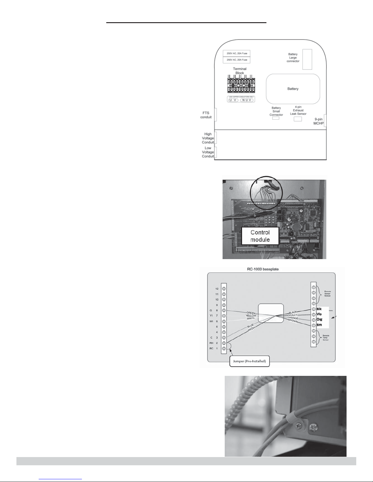
12 - ELECTRICAL WIRING & CONNECTIONS
12.10 Honda MCHP Unit - Line Voltage Connections
Refer to Honda MCHP Installation Manual – Electrical •
Connections Section before performing installation in
this section.
Recommend Breaker: 2-pole; 15 Amp breaker.•
Remove cover plate, install blanking plate, connect •
240 VAC power cable to terminal block on Honda MCHP
unit. Figure 12-5 and 12-10 and Honda MCHP IOM for
details.
Provide and install 240 VAC disconnected switch and •
junction box onto side of boiler or adjacent wall, route circuit
from main service panel to switch and back to
Transfer Switch, see electrical schematics. Route 240 VAC
circuit from
electrical terminal block per Honda MCHP IOM. Do not attach
disconnect switch or junction box onto MCHP unit cabinet.
Do not make penetrations in MCHP cabinet.
Flexible metal conduit is required to provide vibration •
isolation for Honda MCHP. Use NEC conforming,
minimum 4-conductor, 240 VAC dedicated circuit 14
AWG fl exible metal conduit.
Affi x Generator warning label provided to main distribution •
panel where it is clearly seen by any service personnel.
Figure 12-9.
freewatt
Transfer Switch to Honda MCHP’s
freewatt
Figure 12-5 MCHP Connection Details
Figure 12-6 T-Stat Connection to Controller
12.11 HONDA MCHP Unit - Communication
Connections
Connect Honda MCHP to control module with system-•
supplied RS 232 communication cable (with attached
9-pin male connector). Plug connector in upper female
9-pin connector on exterior of right side of freewatt
Control Module. Route MCHP communications cable to
Honda MCHP and connect to communication port on
Honda MCHP.
Install strain relief just outside lower compartment. •
Figure 12-8.
12.12 Smart Zone Thermostat Connections
Refer to instructions supplied with “Zone 2 - Smart Z one”
communicating thermostat for installation and operating
instructions. Connect thermostat cable to thermostat terminal
block, Figure 12-7. Thermostat cable extends from thermostat to
control module, routed through low voltage knockout on control
module enclosure, Figure 12-6.
Install thermostat on inside wall away from infl uences •
of drafts, hot or cold water pipes, lighting fi xtures,
televisions, sun rays, or fi replaces. Install “Zone 2 -
Smart Zone” thermostat in accordance with guidance
provided in Section 2 and 3. (Heating load for Zone 2
Figure 12-7 Thermostat Connections
Figure 12-8 MCHP Low Voltage Wiring Strain
Relief
37
Page 38
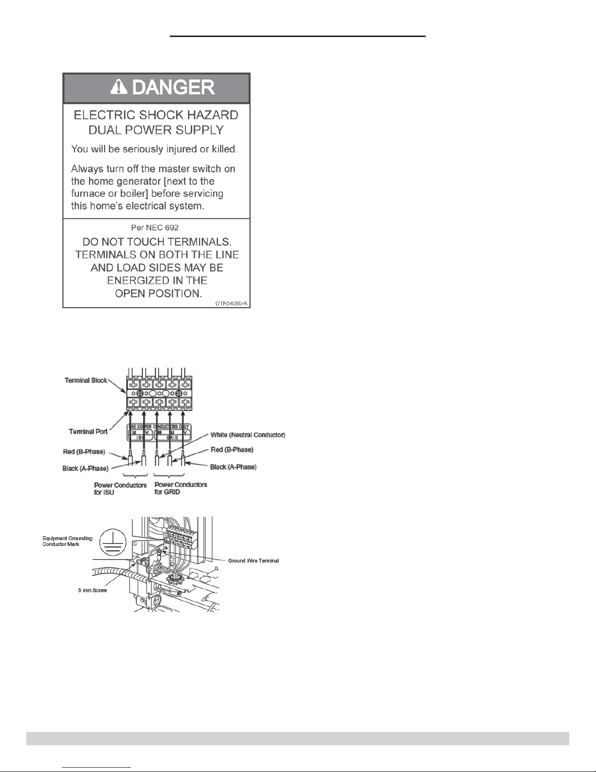
12 - ELECTRICAL WIRING & CONNECTIONS
Figure 12-9 Generator Warning Label
should not less than about 25% of total for building).
Connect thermostat cable to thermostat. Use Honeywell •
Genesis Cable, Model Number 22 AWG 10/C STR CM-CL2 (or
equal) for HAI Smart Zone thermostat. Cable is 22 AWG, 10
Conductor, stranded cable meeting UL Standards 13 & 144,
NEC Article 725. Refer to
Installation manual for additional thermostat connection and
option details.
Route cable to control module. Cable will enter control •
module’s enclosure through top knockout opening. Connect
to control module’s TSAT connections.
Wire all other compatible zone thermostats (new or existing) •
and Indirect Water Heater aquastat per instructions provided
by manufacturer. First six zones (including DHW if used)
connect directly on circuit board of
module. All other zones connect directly to ECR zone relay
control.
freewatt PLUS
freewatt
HAI thermostat
control
Figure 12-10 MCHP Line Voltage Connections
When set in the COOL MODE, •
may be used to control air conditioning system. Remove left
terminal strip metal jumper between Terminal 1 (RC) and
Terminal 2 (RH) on
with ECR ARM-6P or AZ-6CP zone relay controls and separate
cooling 24 VAC transformer (additional to
System transformer) .
Route air conditioning system 24 VAC source •
PLUS
PLUS
to connect directly to Y input of air conditioning system
(do not connect Y to
Use external isolation relay for switching cool signal from
thermostat, if supplied thermostat does not have terminal for
RC.
Wire thermostat for heating and cooling as indicated in wiring •
diagrams for
ARH-3 zone relay control with air handler.
12.13
Mount supplied Tekmar 070 outdoor sensor on outside •
exterior wall per sensor manufacturer’s instructions, shield
from direct sunlight or fl ow of heat or cooling from other
sources. Northern exposure is preferred.
Thermostat using spare grey wire in
thermostat cable. Use Y wire of thermostat cable
Outdoor Temperature Sensor
freewatt PLUS
freewatt PLUS
freewatt PLUS
freewatt PLUS
System confi gurations
freewatt PLUS
control board).
System confi gurations using
thermostat
freewatt
freewatt
Route sensor’s wires through exterior wall into house and •
through knockout on top of control module. Do not combine
wires of Tekmar Outdoor sensor with
Boiler Outdoor Sensor in single cable, electrical interference
will result. See Electrical Schematics.
freewatt PLUS
12.14 Internet Connection
Control module has RJ 45 network connection. Connection found
at right of control module’s enclosure. Connection point accepts
CAT 5e cable.
38
Page 39
12 - ELECTRICAL WIRING & CONNECTIONS
12.15 MCHP Battery Installation
Please see the Honda MCHP manual for
installation of the MCHP battery.
Honda MCHP1.2D/MCHP1.2DP unit requires battery to •
provide power to start up in backup power mode.
Battery is provided for • freewatt
however to insure proper battery storage and charge
level, battery is not packaged with system.
Battery must be ordered at time of installation from •
ECR Customer Service by freewatt dealer performing
installation.
Original battery provided for each • freewatt
System will be shipped to installing dealer at no
charge.
Following information must be provided to obtain •
battery:
Either Honda MCHP Serial Number or A. freewatt
PLUS
System Serial Number.
Your B. freewatt dealer name or dealer number.
Desired ship-to address.C.
Call ECR freewatt Customer Service toll free at 866-9446247 to order battery.
PLUS
System,
PLUS
NOTICE
IMPORTANT - Honda MCHP unit will not operate without a
battery. Use only battery specifi cally designed for use in
Honda MCHP.
39
Page 40

13 -COMMISSIONING AND STARTUP
13.1 For System commissioning and startup procedures,
refer to literature packet document “Hydronic freewatt
PLUS System, Model HDJ Commissioning Procedure”.
You may also refer to the Commissioning Procedure
Manual for basic
operation.
freewatt
PLUS system sequence of
40
Page 41
14 - MAINTENANCE AND CLEANING
!
WARNING
Disconnect electrical power supply to freewatt PLUS
System before attempting any maintenance. Failure
to do so can cause electrical shock resulting in
personal injury or loss of life.
!
WARNING
Label all wires prior to disconnection when servicing
controls. Wiring errors can cause improper and
dangerous operation. Always verify proper oper ation
after servicing.
Review maintenance and cleaning procedures as outlined in
Installation, Operation and Maintenance Manuals of boiler
and Honda MCHP before proceeding with procedures below.
Regular service and maintenance by qualifi ed service
agency must be performed to assure safe, trouble-free
operation and maximum effi ciency. Service or inspect
system at least once every 12 months.
Honda MCHP unit requires periodic inspection by certifi ed
service professional to maintain acceptable performance
and ensure safe operation. Inspection/service procedures
are outlined in unit’s Installation, Operation and
Maintenance Manual. Services are required every 6,000
hours, operating time of unit will directly impact service
interval. Inspections include, but are not limited to:
14.1 Beginning of Each Heating Season
Schedule annual service by
certifi ed service agency, to include:
Examine boiler as described in annual inspection, •
service procedures outlined in boiler Installation,
Operation and Maintenance Manual. Inspections
include, but are not limited to:
Heat Exchanger’s Flue Passageways•
Burner•
Combustion Fan•
Circulator•
Electrical Connections•
Condensate Drain•
Intake Air and Exhaust Piping•
Boiler Operation (Safety, Temperature Rise & Burner •
Ignition)
Examine control module/HI Module per annual •
inspection/service procedures outlined below:
Control Module: Using laptop computer or PDA •
check control module’s functions. Detailed
procedures found in MINT Tool Supplement.
Communication/Electrical Connections: Inspect •
connections to and within Control Module and HI
Module. Verify they are secure and connected
properly.
Bypass Switch: Place CHP Mode Switch in OFF •
position and operate boiler to verify CHP mode
switch is working properly. Place CHP mode switch
in ON position after verifi cation is complete.
freewatt PLUS
dealer or
MCHP Owner’s Manual outlines specifi c maintenance
intervals (6,000, 12,000, 18,000 & 24,000 hours) and
requirements for each interval. Maintenance should be
performed by service professional to maintain performance
and ensure safe operation of your Honda MCHP.
Coolant Level: Check coolant level in coolant tank •
and fi ll with coolant, if necessary.
Mixing Valve: Check coolant temperature being •
delivered by valve while system is operating. Check
for leaks and fi x, if necessary.
Pump: Inspect pump and connections. Check for •
leaks and fi x, if necessary.
Coolant Tubing and Connections: Inspect coolant •
tubing and connections for leaks and fi x, if
necessary.
Brazed Plate Heat Exchanger: Inspect heat •
exchanger for leaks and fi x, if necessary.
Starting Ease•
Oil Leakage•
Engine Coolant•
Breather Tube•
Condensate and Condensate Drain•
Air Cleaner Element•
Intake Air and Exhaust Piping•
Ventilation Air Inlet and Outlet•
Coolant Tubing and Connections•
Electrical System and Connections•
Communication System and Connection•
Replace:•
Engine Oil and Drain Washer.
a.
Engine Oil Filter Cartridge.
b.
Spark Plugs.
c.
Adjust Clearance Between Tappets.
d.
41
Page 42
14 - MAINTENANCE AND CLEANING
14.2 Draining Procedure
It may be necessary to drain system during maintenance
operations. Follow procedure below:
NOTICE
Use caution while servicing and disposing of coolant
in proper manner. MCHP coolant is 50/50 ethylene
glycol solution and is toxic. Glycol is specially
formulated with bittering agent to discourage
ingestion.
Wait for coolant to cool down if system has been
operating. Several hours may be necessary to cool
coolant fl uid to safe working temperature.
Use precautions while collecting coolant. Coolant
may fl ow at high rate due to pressure in system.
Shutdown Procedure:
1.
Preferred Method: Set thermostat to OFF by A.
pressing Mode button until display reads OFF. Turn
SYSTEM POWER switch to off after shut down cycle
of approximately three minutes is completed.
Emergency Method: Turn SYSTEM POWER and B.
BYPASS switch to OFF. MCHP may overheat and
fl ash error message due to coolant pump turning
off.
Inspect coolant connections on MCHP unit and integral
2.
brass drain valve when coolant achieves a safe working
temperature.
Place towel under drain valve.
3.
Verify valve’s position is OFF, slowly remove drain cap.
4.
Connect short hose to drain valve and extend to
5.
coolant container pan.
Open valve and evacuate coolant from system.
6.
Coolant tank’s cap may need to be taken off to remove
vacuum.
Verify tubing loops are open to prevent any vacuum
effect to adversely impact draining operation. If
coolant has under 24,000 hours of operation and is
clean, reuse when refi lling system.
It is recommended to evacuate lines with aid
of LOW pressure (under 5 psi) compressed air.
Alternatively, hand pump can be used.
42
Page 43
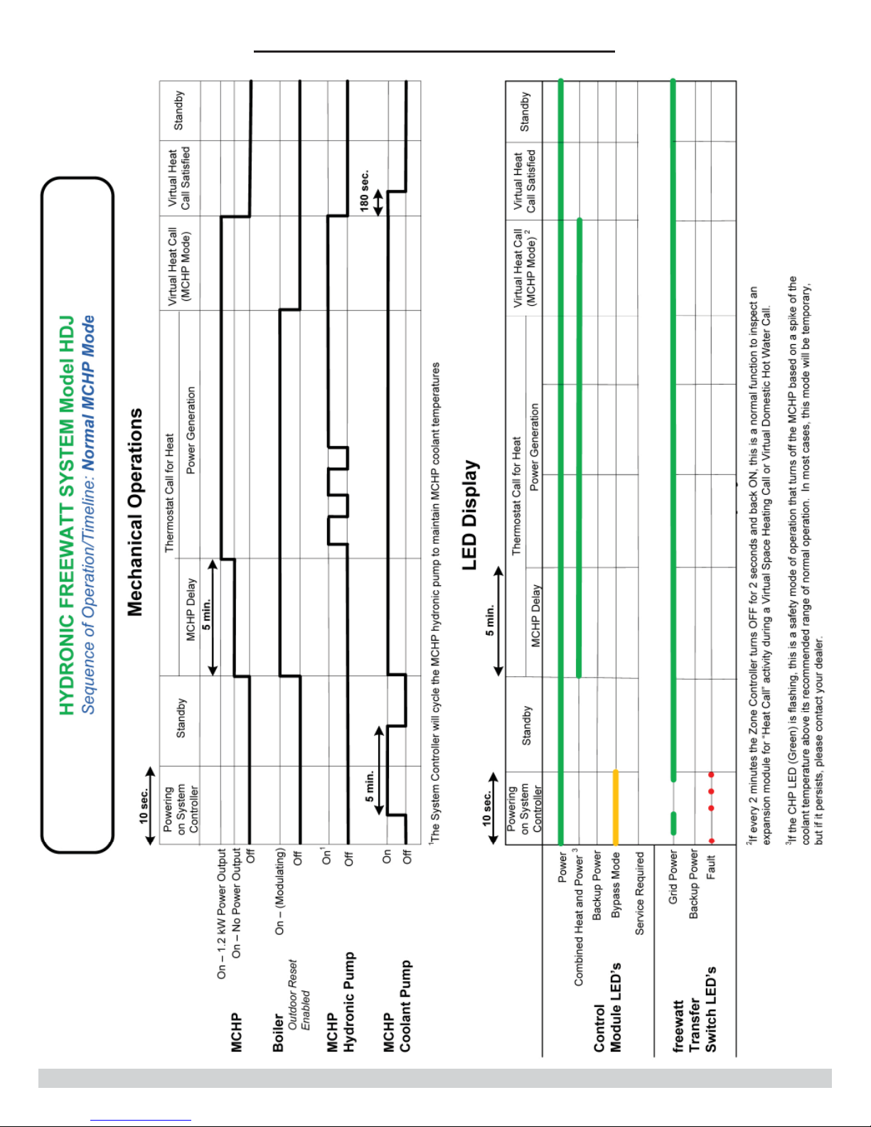
15 - DETAILED SEQUENCE OF OPERATION
43
Page 44
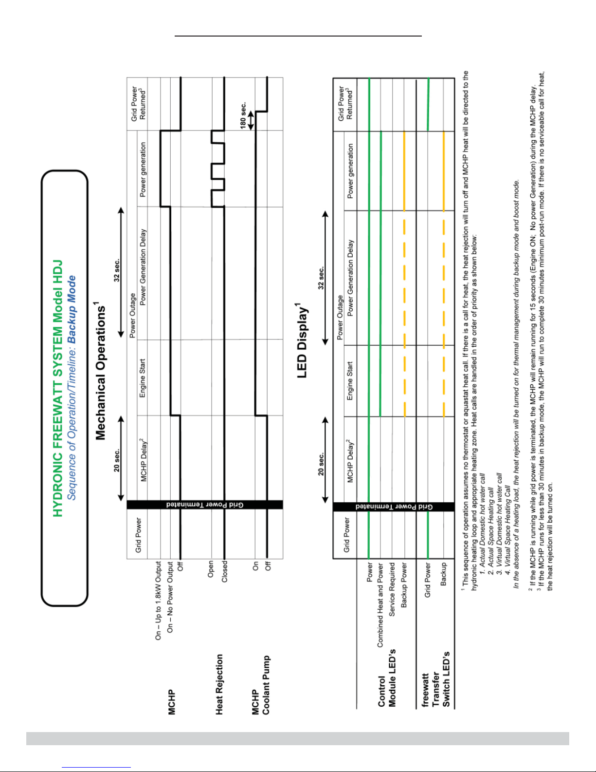
15 - DETAILED SEQUENCE OF OPERATION
44
Page 45

15 - DETAILED SEQUENCE OF OPERATION
15.1 MCHP Operation:
freewatt PLUS
• System is designed to preferentially
provide heat to home and indirect water heater by
operating MCHP unit.
Boiler is operated as supplemental heat supply as •
needed to maintain comfort.
Preferential operation of MCHP is achieved by •
allowing MCHP to operate at times when thermostat
does not specifi cally call for heat, but, based on
outdoor temperature, continuing need for heat can
be established. Homeowner should expect MCHP to
“run” longer and more often than boiler, even when
thermostat may not indicate call for heat.
freewatt PLUS
• System designed to maintain close
control of building temperature. Variations in room
temperature should be less than traditional thermostats
with operating temperature dead band.
15.2 freewatt PLUS
System Response to Heat
Demands:
freewatt PLUS
call for heat from thermostat or aquastat on indirect water
heater. Does not directly respond to electrical power demands in home. Response of
heat calls follows:
Upon demand for heat from any space heating •
zone, hydronic water fl ow to zone “radiators” is
initiated, MCHP unit is started and boiler operation
is enabled. Burner in boiler will fi re as necessary to
maintain current required hydronic loop temperature
as determined by programmed outdoor reset control
of boiler. Boiler initially fi res at lowest input rate
and modulates to higher levels as determined by
temperature response of hydronic loop temperature.
Smart Zone operation of MCHP unit, initiated by call for •
heat, will continue beyond specifi c call for heat from
Smart Zone thermostat as long as outdoor temperature
sensor indicates general need for heating of building
(i.e. outdoor temperature about 55° F). Boiler
operation is disabled immediately at end of call for heat
from Smart Zone Thermostat. Operation of MCHP unit
is terminated only when there is small temperature
rise above current set temperature of Smart Zone
Thermostat.
System heating function is activated by
freewatt PLUS
System to
Operate domestic water heating zone without •
causing unacceptably high temperature in MCHP
coolant. Boiler burner operation is disabled
immediately upon end of call for heat.
For zones with room thermostats wired directly to •
ECR relay control or any ECR expansion relay control,
operation of MCHP and boiler burner will terminate with
end of heat call (either from initiating zone or any other
zone.)
Call for heat by Aquastat of indirect water heating •
tank Zone 1, when Zone 1 is confi gured for heating
of domestic water. Water heating zone pump starts,
MCHP operates, boiler burner is enabled to maintain
temperature programmed as domestic water heating
temperature (
33). Boiler burner is disabled and MCHP continues to
operate when Aquastat is satisfi ed, until
control module has determined it is not possible to:
Operate Smart Zone without exceeding small •
temperature rise above Smart Zone spacing heating
setpoint or
Operate domestic water heating zone without •
causing unacceptable high temperature in MCHP
coolant.
MCHP coolant temperature is monitored internally and •
reported to
terminates automatically by
and disabled for period of time ranging from 15
minutes to three hours if MCHP coolant reaches 185°F.
Occurs when current target temperature of boiler
control is high (about 160° F or above.). Can also
occur if boiler temperature boost mode is not disabled
as recommended. In either case,
module logic takes into account frequency which 185°F
coolant temperature is reached and determines how
long to disable operation of MCHP unit. Operational
logic limits number of times MCHP is started and
stopped in presence of high hydronic loop temperature.
Default setup of •
minute priority to DHW heating when DHW jumper is in
place. Priority action pertains to achieving satisfaction
of indirect water heater aquastat (not virtual heat
call operation of MCHP unit.) Priority action can be
deactivated by using Mint Service Tool.
freewatt PLUS
freewatt
control module. MCHP operation
freewatt
boiler parameter 1 +
freewatt
freewatt
control module provides 30
control module
freewatt
control
For other heating zones with room thermostats wired •
directly to
MCHP will continue until initiating zone, or any new
heat demand zone is satisfi ed and
module determines it is not possible to either
Operate Smart Zone without exceeding small •
temperature rise above Smart Zone setpoint or
freewatt
control module, operation of
freewatt
control
45
Page 46

15 - DETAILED SEQUENCE OF OPERATION
15.3 Achieving Best
freewatt PLUS
System
Performance
Homeowner dollar, carbon dioxide emissions, and energy
saving with
operating parameters of boiler and thermostat to achieve
maximum preferential operation of MCHP unit (and
minimum fi ring of boiler).
Following steps will help in maximizing benefi t of
PLUS
Set top target temperature of boiler reset operating •
temperature control (parameter 4) at lowest possible
temperature that will meet heating needs of home
on coldest days of year. Recommended maximum
top target temperature is 160°F per Commissioning
Procedure. Setting top target temperature greater than
160°F will signifi cantly reduce operation of MCHP unit
and resulting electric power production. Set target
temperature lower if possible.
Set Aquastat on indirect water heater no greater than •
125°F.
Although it is contrary to modern heating system •
practice, it is recommended to avoid using setback with
freewatt PLUS System. Using setback will typically
cause Honda MCHP to shut down during setback
hours as thermostat will be satisfi ed, particularly
during early stages of setback. This reduces MCHP
run hours and power generation signifi cantly, thus
reducing electric bill savings and cost effectiveness
of freewatt system. Coming out of setback
requires the freewatt boiler to run more to make
up additional heat demand. Setting thermostat at
a constant temperature and leaving in there will
maximize comfort, power generation and electric bill
savings. Set it, forget it, and save.
freewatt PLUS
System.
is maximized by adjusting
freewatt
Select Smart Zone and confi gure if necessary, so it •
represents at least 25% of total heat demand of home.
Set individual zone thermostats so Smart Zone set •
point is about (1 or 2 degrees) above other zones in
home will help maximize production of electricity by
freewatt PLUS
Set •
freewatt PLUS
Commissioning Procedure. Turns off temperature boost
feature of boiler control. If occupants are dissatisfi ed
with response of heating system to thermostat set
point adjustments, consider altering outdoor reset
curve, using Parameters 4, 5, 6, and 7 before adjusting
Parameter 11 to non-zero setting. Keeping parameter
11 at zero is benefi cial when there are heating zones
that do not have critical heating comfort requirements
but will produce nearly constant call for heat. Near
constant call for heat can result from heating zone
being “under radiated” or heat convectors being closed
off.
freewatt PLUS
zones have appropriate amount of radiation.
System.
boiler parameter 11 to zero per
performs best when all heating
46
Page 47
16 - TROUBLESHOOTING
!
WARNING
Fire, explosion or risk of shock hazard may cause
severe injury or death. Do not attempt to modify
characteristics of this home heating appliance in any
way.
16.1 Troubleshooting Tools
Voltmeter with settings to check: 240 VAC, 120 VAC, •
24 VAC and 12 VDC;
Continuity Tester;•
Contact Thermometer; (Non-Contact Infrared •
Thermometer)
Manometer with range of 0 to 20” of water column.•
Laptop Computer Loaded with MINT Software Tool.•
16.2 Initial Service Checks
Verify appropriate 120 VAC and 240 VAC circuit •
breakers at main service panel are ON. Check outdoor
disconnect switch, where applicable, is ON.
Verify 240 VAC and 120 VAC electric service switches •
are turned ON.
Check for 120 VAC (minimum 108 VAC to 132 VAC) to •
system.
Check for 240 VAC (minimum 216 VAC to 264 VAC) to •
Honda MCHP.
Verify thermostat in Heat Mode.•
Verify thermostat is calling for heat on system control. •
If not, inspect thermostat connections to ensure proper
contact.
Verify external safety controls are installed and working •
properly.
Verify natural gas supply valve is open at gas meter, •
manual shutoff valves and gas control valve. Gas
pressures are maximum of 10” w.c. (natural gas)
or 14” w.c. (propane) with no fl ow or with system
operating and minimum of 4” w.c.(natural gas) or 10”
w.c. (propane) with gas fl owing at maximum fi ring rate
of
freewatt PLUS
with boiler and Honda MCHP operating simultaneously).
Check wire connectors at control module, boiler control •
and Honda MCHP are securely plugged in or connected.
If any component does not function properly, verify it is •
correctly installed and wired before replacing it.
Static electricity discharge can damage control module •
and boiler control. Touch metal surface to discharge
static electricity before touching either control.
The control module and boiler control cannot be •
repaired. If either or both controls malfunction, the
control unit must be replaced.
boiler (verify during system startup
Only trained, experienced service technicians •
should service control systems. Follow “Sequence
of Operation” for normal light off sequence after
troubleshooting.
If two consecutive controls appear to fail or appear •
defective, control is probaly not defective. Another
problem may give appearance controls are defective
or fail (for example, electrical short burning out
transformer).
Check coolant tubing extending from Honda MCHP •
to Hydronic Hybrid Integration Module is securely
connected and not plugged or damaged.
Check coolant operating temperature. Using MINT •
tool, confi rm coolant entering MCHP unit is in range of
152-154° F. Check coolant tank in Hydronic Hybrid
Integration Module verify fi lled to above MIN. level line.
(Preferred level is just below MAX line.)
47
Page 48
16 - TROUBLESHOOTING
!
WARNING
Electrical shock hazard may cause serious injury
or death. Avoid touching live electrical contacts.
Service shall be performed by trained, experienced
service technician.
!
WARNING
WHAT TO DO IF YOU SMELL GAS
Do not try to light or start any appliance.
Do not touch any electric switch or use any phone in
the building.
Immediately call your gas supplier from a neighbor’s
phone. Follow gas supplier’s instructions.
If you can not contact your gas supplier, call fi re
department.
!
WARNING
Fire or explosion hazard. Use only your hand to
turn gas control knob. Never use tools. If knob will
not turn by hand, don’t try to repair it. Force or
attempted repair may result in a fi re or explosion.
!
WARNING
Fire or explosion hazard. If overheating occurs
or gas supply fails to shut off, do not turn off or
disconnect electrical supply to boiler or hydronic
hybrid integration module. Shut off gas at location
external to appliance.
16.3 Accessing
freewatt PLUS
System
Operational Data and Codes
Multiple means of accessing hydronic
System operational data and error codes for purposes of
troubleshooting.
Observe and count number of fl ashes of red “Service •
Required” LED on front of
See Table 16-1 “Alarm Codes for Service Required LED
on
freewatt
Observe fl ash rate of green LED on front of •
c
ontrol module labeled “Combined Heat and Power”.
(See Table 16-2 “Alarms Codes for Combined Heat and
Power LED on
Observe status (lighted or not) of 10 LEDs on •
freewatt
(Remove cover to observe.) See Table 16-3.
Read boiler operation error code on •
boiler electronic front panel per
Control Manual and Troubleshooting Guide.
Use MINT software on portable computer connected to •
freewatt
operating data and error codes for
System and Honda MCHP unit per MINT software
Manual.
Remove metal cover of control panel on MCHP (located •
upper left side of unit) and read error codes per Honda
MCHP Installation and Operation Manual.
freewatt PLUS
• systems operate with RC-1000 HAI
thermostat, note color of thermostat display (red for
fault/alarm condition) and read
module error message display. Error messages same
as “Alarm Codes for System Service LED on
Control Module”.
control module”.
freewatt
control board in
control module to display
freewatt
control Module”.
freewatt PLUS
control module.
freewatt
control module.
freewatt PLUS
freewatt PLUS
freewatt PLUS
freewatt PLUS
freewatt
freewatt
Boiler
control
freewatt
!
WARNING
Fire or explosion hazard. Do not use system if any
part of gas control system (boiler or MCHP unit)
has been underwater. Contact qualifi ed service
agency to inspect system and replace any part of
control system and any gas control which has been
underwater.
48
Call ECR •
representative.
freewatt PLUS
Technical Support
Page 49
16 - TROUBLESHOOTING
16.4 General Troubleshooting
If And Check or repair
No Control module
or HI Module
operation
No boiler operation
Honda MCHP
overheats
No power to
thermostat
Display
is blank
120 VAC electrical connections
Blown fuse on
control module circuit board
Thermostat settings
Check Boiler per
PLUS
and Troubleshooting Guide
Check Control Module
Connection
Fuse in thermostat 24VAC
Fuse in
module
or Faulty wire connection
Boiler Control Manual
Coolant Pump •
functioning Properly
Circulators Functioning •
Properly
Air in Coolant Line•
Coolant Line Blocked•
Coolant lines piped •
correctly into Honda
MCHP
Mixing valve setting•
freewatt
freewatt
freewatt
control
Hydronic
components:
• Control Module,
• HAI Thermostat,
• Transfer Switch,
Each major component has its own installation and service
manual outlining troubleshooting information regarding
individual component.
Make corrective action. Turn off power and restart system
to clear error conditions.
Use BYPASS MODE, (CHP MODE OFF) to sustain heating
operation while resolving
MCHP unit errors or malfunctions.
freewatt PLUS
Boiler, •
freewatt
Hydronic •
Module,
Honda MCHP, •
freewatt
freewatt
Load Balancing Transformer and •
APC Universal Transfer Switch •
freewatt PLUS
System consists of eight major
Hybrid Integration (HI)
freewatt
control module or
No Honda MCHP
operation
See MCHP Manual
49
Page 50
16 - TROUBLESHOOTING
Table 16-1 Alarm Codes for Service Required LED on freewatt
ERROR
CODE
1
2
3
4
5
6
7
8
9
10
11
12
13
14
15
16
17
18
19
20
21
22
23
24
25
26
27
28
29-98
99
THERMOSTAT COMMUNICATIONS ERROR
MCHP COMMUNICATIONS ERROR
MCHP DEVICE ERROR (MCHP ASSERTING “FAILURE” STATUS, IE. A HARD ERROR) CHECK HONDA MCHP DIAGNOSTICS
MCHP DEVICE WARNING (MCHP ASSERTING “WARNING” STATUS, IE. A SOFT ERROR)
freewatt
SYSTEM POWER SWITCH OFF, UNABLE TO ENTER BACKUP MODE (NOTE: NOT DEFINED IN HY-
MCHP PLACED IN LOCKED MODE BY SERVICE TECH, PREVENTS MCHP OPERATION
LOW DWELLING TEMPERATURE. BOILER DOWN OR THERMOSTAT “OFF” BY MISTAKE
VIRTUAL WATCHDOG TIME-OUT. AN UNEXPECTED FIRMWARE EXECUTION ERROR
EXHAUST GAS LEAK SENSOR FAILURE, HONDA MCHP ERROR 39.0 (EX_SENS_FAIL)
EXHAUST GAS LEAK SENSOR POWER FAILURE, HONDA MCHP ERROR 39.1,(EX_SENS_POWER_
EXHAUST GAS LEAK SENSOR ALARM, COMBUSTION GAS DETECTED, HONDA MCHP ERROR 10.1,
NO DC POWER SUPPLY VOLTAGE DETECTED IN BACKUP MODE. (LOAD_PWR_FAULT)
DETECTED A freewatt
DETECTED A freewatt
DETECTED A freewatt
DETECTED A freewatt
DETECTED A freewatt
VOLTAGE DETECTED ON THE freewatt
VIRTUAL WATCHDOG TIME-OUT OCCURRED 5 OR MORE TIMES. MULTIPLE UNEXPECTED FIRM-
PLUS
EXHAUST GAS LEAK SENSOR TEST BUTTON PRESSED
MISSING L1 OR L2 OF AC POWER (fTS_AC_FAULT)
WARE EXECUTION ERRORS OCCURRED.
INDICATES CHECK OR REPAIR
OUTDOOR SENSOR ERROR
FLASH PARAMETER INTEGRITY CHECK ERROR SERVICE REQUIRED
DRONIC SYSTEM)
RESERVED FOR FUTURE USE
ERROR CODE 10 NOT USED
RESERVED FOR FUTURE USE
OCCURRED.
FAIL)
(EX_LEAKAGE_FAIL)
PLUS
TRANSFER SWITCH COMMUNICATIONS FAILURE Check fTS communications cable
PLUS
TRANSFER SWITCH DEVICE ERROR see freewatt
ERROR CODE 20 NOT USED
PLUS
TRANSFER SWITCH STATE ERROR see freewatt
RESERVED FOR FUTURE USE
PLUS
TRANSFER SWITCH CONTACTOR #1 ERROR see freewatt
PLUS
TRANSFER SWITCH CONTACTOR #2 ERROR see freewatt
PLUS
BACKUP POWER MODE
RESERVED FOR FUTURE USE
RESERVED FOR FUTURE USE
TRANSFER SWITCH ISLAND NODES (I1 OR I2) IN
Control Module
1. CHP MODE SWITCH IN
2. CABLES AND CONNECTIONS BETWEEN
THE THERMOSTAT AND THE HI MODULE
3. LOWER FURNACE ACCESS PANEL
INSTALLED
4. IMPROPERLY PROGRAMMED
THERMOSTAT
1. CHECK OUTDOOR SENSOR AND CONNECTION OR INTERNAL 20k OHM DEFAULT
RESISTOR
1. RESET SYSTEM POWER
2. POWER TO MCHP
3. CABLES AND CONNECTIONS BETWEEN
HONDA MCHP AND HI MODULE
REPLACE CONTROLLER MODULE
INDICATES A FAULT IN 120V LOAD
CIRCUIT
transfer switch IOM
transfer switch IOM
transfer switch IOM
transfer switch IOM
see freewatt
BLOWN FUSE, FAULTY WIRING, UTILITY
FAULT
REPLACE CONTROL MODULE
transfer switch IOM
ON
POSITION
50
Page 51
16 - TROUBLESHOOTING
Table 16-2
16.6 Control Board LED Interpretation
Alarms Codes for Combined Heat and Power LED on
freewatt
Combined Heat Power
LED Status
Rapid Flash
(~5 per second)
Control Module
Condition
MCHP operation suspended
on detection of high coolant
temperature
Steady ON Normal MCHP Operation
16.5 MCHP Suspended Mode
Table 16-3
MCHP operation will be suspended if there is detection of
high coolant temperature, indicated by rapidly fl ashing
Combined Heat and Power LED. MCHP Suspend Mode
prevents MCHP unit from cycling in overheat situation
in which it cannot run. Condition may be due to boiler
temperature set higher than recommended, improperly
commissioned system, or high aquastat setting on indirect
hot water tank. Perform following tasks if suspend
condition is encountered.
Check boiler parameters• . Hydronic freewatt system
has maximum recommended design water temperature
of 160° F. Suspend mode will occur and effect overall
MCHP ENB MCHP enabled MCHP disabled
MCHP runtime and power generation, if boiler water
temperature is higher than 160° F.
Check aquastat on indirect water tank is set no •
higher than 125° F. MCHP may not run while boiler
is satisfying indirect hot water tank, if aquastat must be
set higher for hot water recovery.
Ensure fl ow is presen• t in coolant loop and hydronic
loop (check for working pumps).
Ensure system is properly commissioned• per
Hydronic Commissioning Procedure.
Observe green LEDs on control board by removing •
cover of
freewatt
Control Module.
Control Board LEDs are valid only in Combined Heat •
and Power Mode (CHP Mode switch “ON”). They are not
used when system is in Bypass Mode (CHP Mode switch
“OFF”).
Do not use Control Board LEDs as indicator of system •
status when in Bypass Mode.
Controller Board LED’s indicate:
LED ON LED OFF
Z1 Zone 1 circulator ON Zone 1 circulator OFF
Z2 Zone 2 circulator ON Zone 2 circulator OFF
Z3 Zone 3 circulator ON Zone 3 circulator OFF
Z4 Zone 4 circulator ON Zone 4 circulator OFF
Z5 Zone 5 circulator ON Zone 5 circulator OFF
Z6 Zone 6 circulator ON Zone 6 circulator OFF
X1X2
MyEND
PUMP1
PUMP2
PUMP3 Not used Not used
Relay XX end switch
relay closed
freewatt
Module closed either
DHW or CH input to
boiler, requesting
boiler operation
24 VDC coolant pump
in HI Module energized
120 VAC Hydronic
circulator connected to
HI Module energized
through external relay
switch
Control
Relay XX end switch
relay open
freewatt
Module not requesting
boiler operation
24 VDC coolant pump
not energized
120 VAC Hydronic
circulator not
energized
Control
NOTE: One or more zone circulators may be activated
without specifi c call for heat by room thermostats or DHW
aquastat consequence of control logic anticipating heat demand and attempting to maximize MCHP run time.
51
Page 52
16 - TROUBLESHOOTING
16.6 freewatt
PLUS System Fuses
!
WARNING
Do not jumper fuse. Replace specifi ed as listed.
Failure to comply could result in severe personal
injury, or death.
!
WARNING
Label all wiring prior to disconnection when servicing
controls. Wiring errors can cause improper and
dangerous operation. Disconnect power to system
before servicing. Failure to comply could result in
severe personal injury or death.
NOTICE
Check control module fuses before replacing control
module or other major component (pump, motor,
etc.). Blown fuse may prevent system control
module or other components from operating.
NOTICE
On board fuses are not available from ECR
International. Service technicians should provide
fuses for
freewatt
PLUS service from local suppliers.
Refer to Table 16-4.
Table 16-4 freewatt PLUS System Fuses
Location QTY Amp Voltage Spares Shape Size
Control Module (Control board, GDB Fuse) 1 2 250 0 Cylinder 5mm X 20mm
Boiler (Control Board F1, Lower RH Corner) 1 5 250 2 Cylinder 5mm X 20mm
Boiler (Control Board F3, Middle Right Side) 1 4 250 2 Cylinder 5mm X 20mm
MCHP* 1 1 650DC 0 Cylinder 6.35mm x 32mm
MCHP * 2 20 600AC 0 Cylinder 10.3mm x 38.1mm
APC UTS6H Control Board
(Use Littlefuse KLKR15 or eqiv.)
* Refer to MCHP Shop Manual
6 15 600AC
0
Cylinder 10.3mm x 38.1mm
52
Page 53
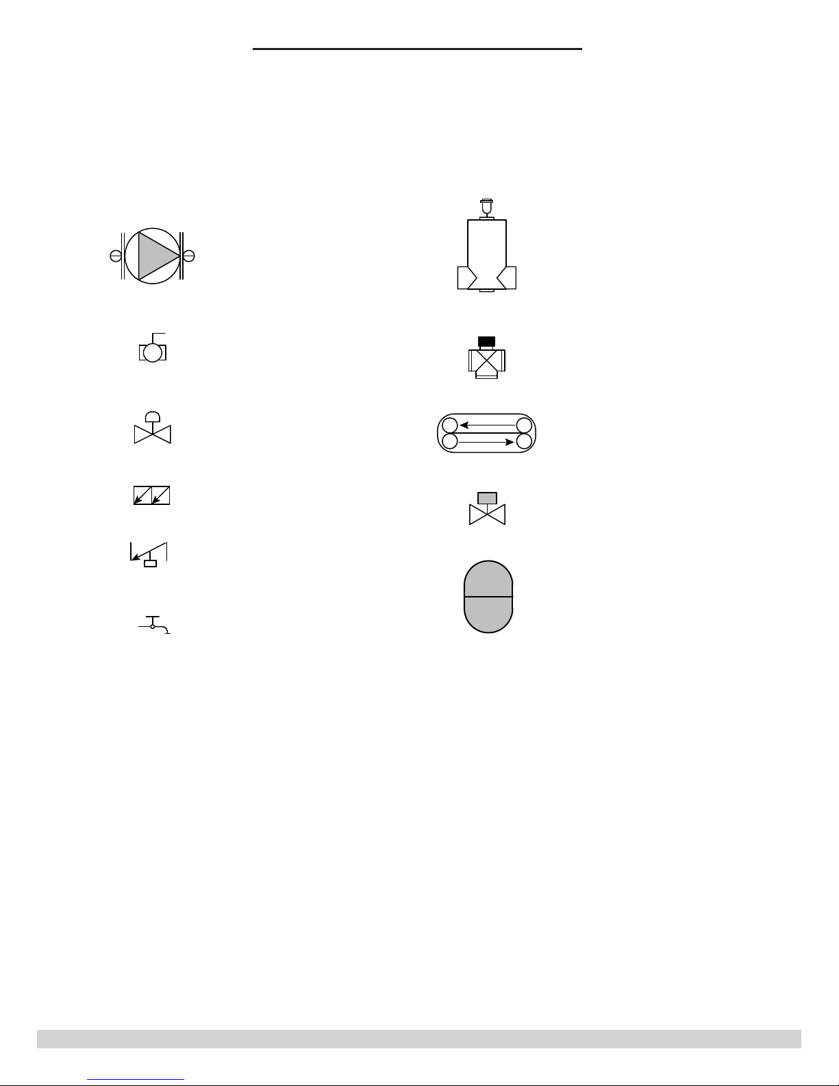
17 - PIPING AND WIRING SCHEMATICS
17-1 Piping Schematic Symbols
CIRCULATOR
(With Isolation Flanges)
BALL VALVE
PRESSURE
REDUCER VALVE
BACKFLOW PREVENTER
FLOW CHECK VALVE
BOILER DRAIN VALVE
AIR SEPARATOR
3 WAY MIXING
VALVE
HEAT EXCHANGER
ZONE VALVE
EXPANSION TANK
53
Page 54
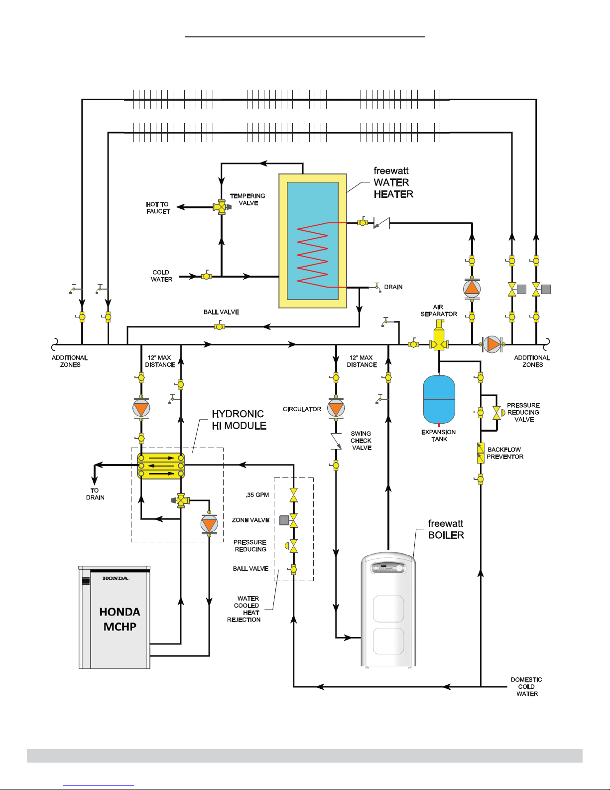
17 - PIPING AND WIRING SCHEMATICS
17-2 Primary/Secondary Piping With Zone Valves and Domestic Hot Water Priority Circulator
54
Page 55
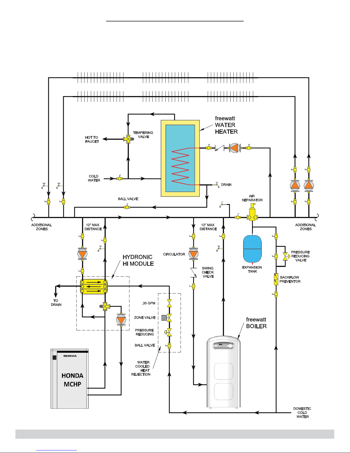
17 - PIPING AND WIRING SCHEMATICS
17-3 Primary/Secondary Piping With Circulators and Domestic Hot Water Priority Circulator
55
Page 56
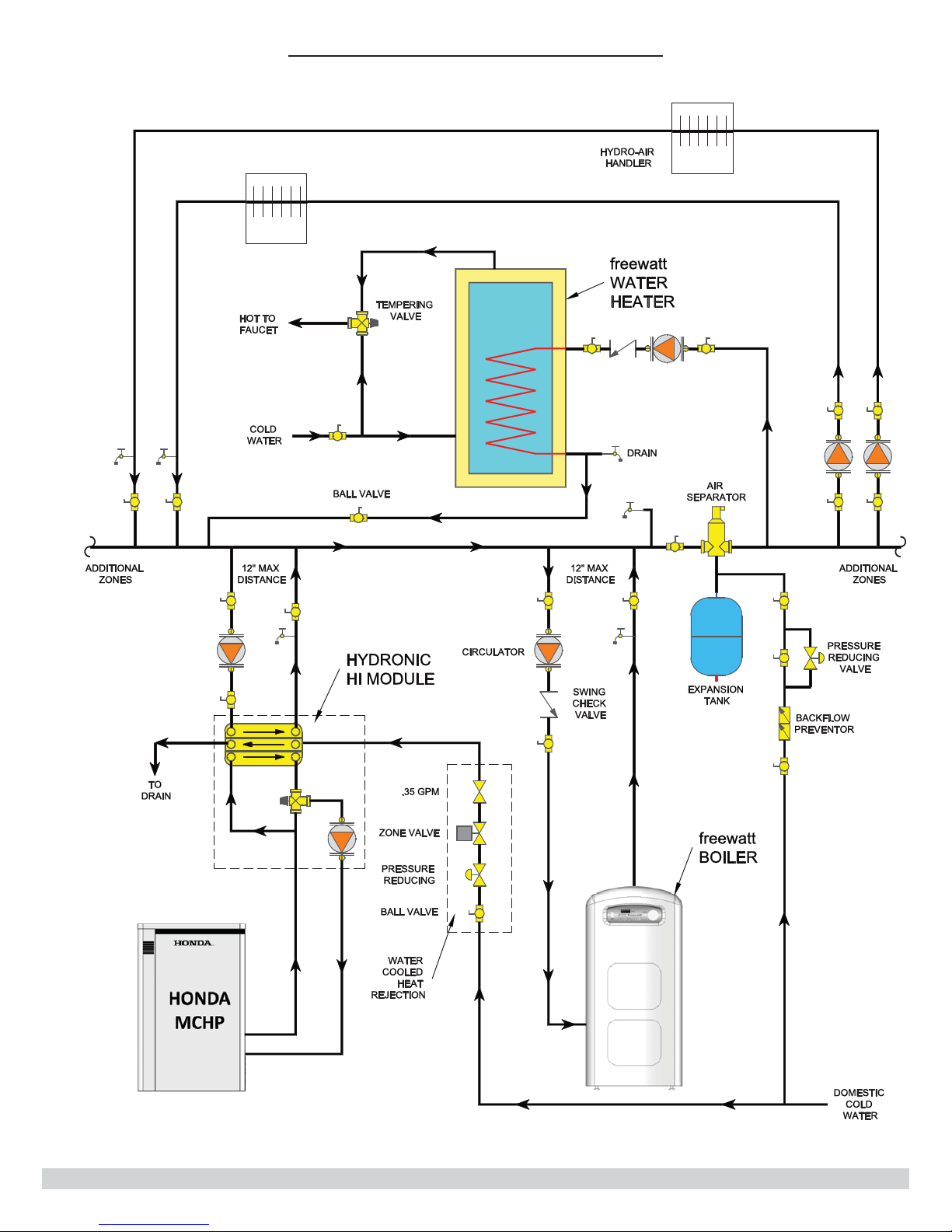
17 - PIPING AND WIRING SCHEMATICS
17-4 Primary/Secondary Piping With Hydro-Air Handler and Domestic Hot Water Priority Circulator
56
Page 57
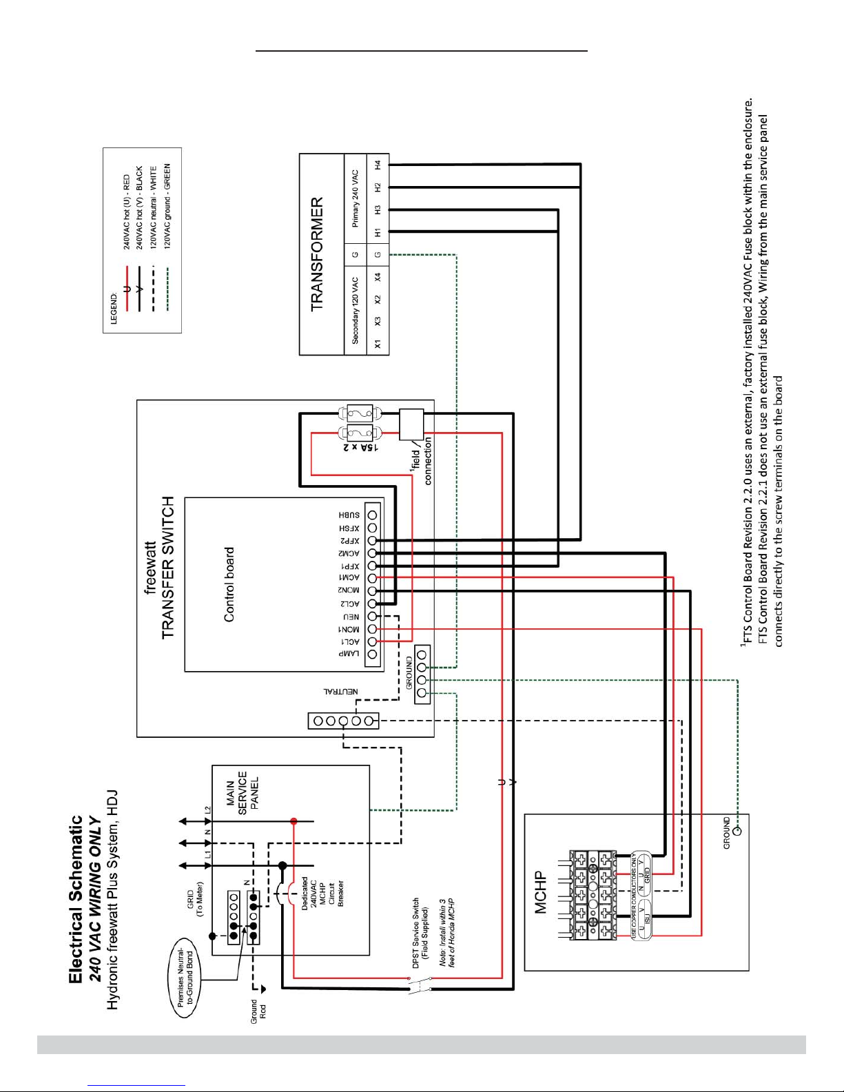
17 - PIPING AND WIRING SCHEMATICS
17-5 HDJ - 240 VAC Wiring Only
57
Page 58
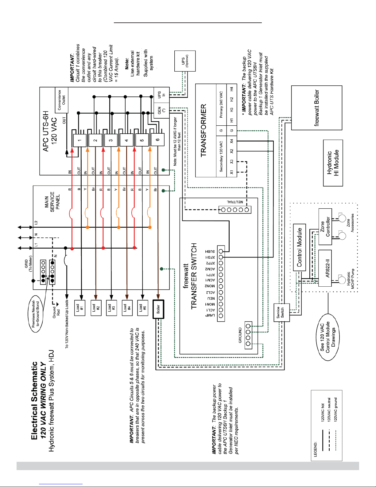
17 - PIPING AND WIRING SCHEMATICS
17-6 HDJ - 120 VAC Wiring Only
58
Page 59
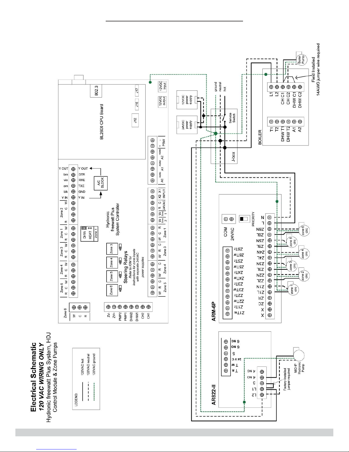
17 - PIPING AND WIRING SCHEMATICS
17-7 HDJ - 120 VAC Wiring - Control Module & Zone Pumps
59
Page 60
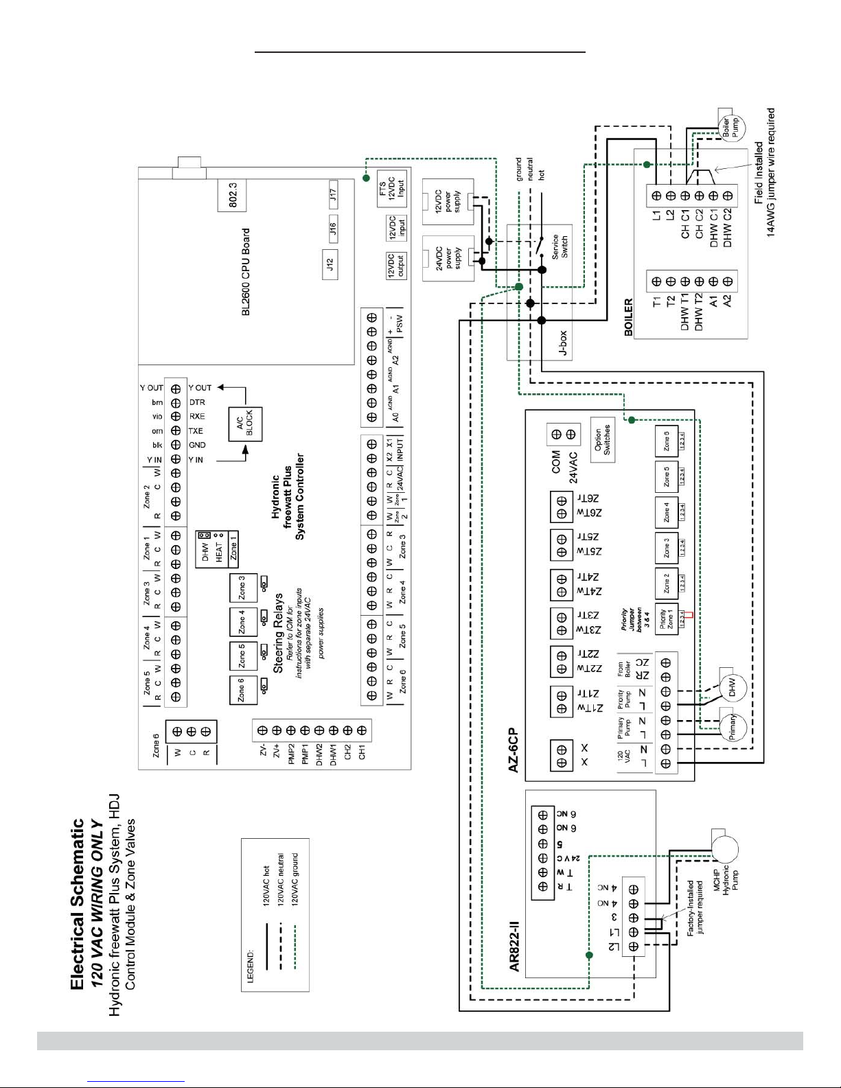
17 - PIPING AND WIRING SCHEMATICS
17-8 HDJ - 120 VAC Wiring - Control Module & Zone Valves
60
Page 61
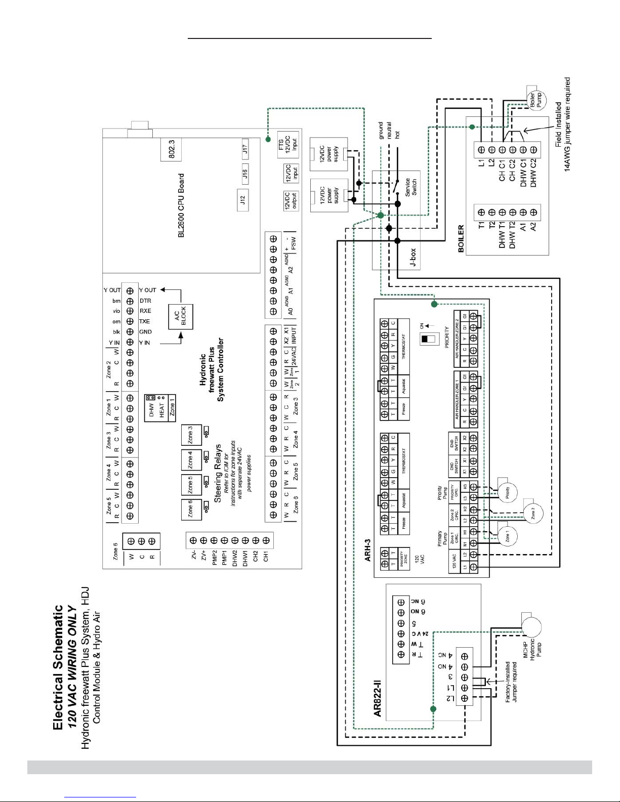
17 - PIPING AND WIRING SCHEMATICS
17-9 HDJ - 120 VAC Wiring - Control Module & Hydro Air
61
Page 62
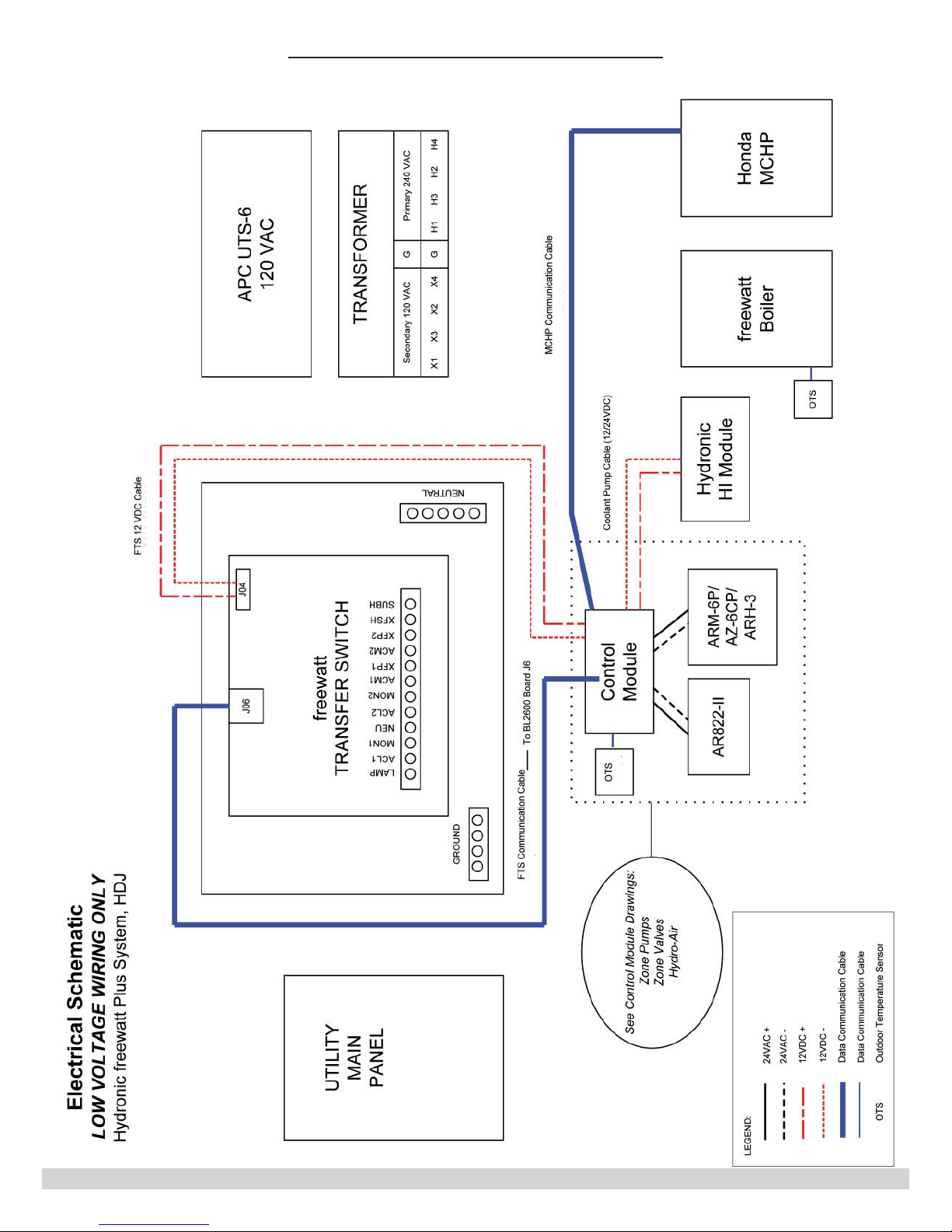
17 - PIPING AND WIRING SCHEMATICS
17-10 HDJ - Low Voltage Wiring Only
62
Page 63
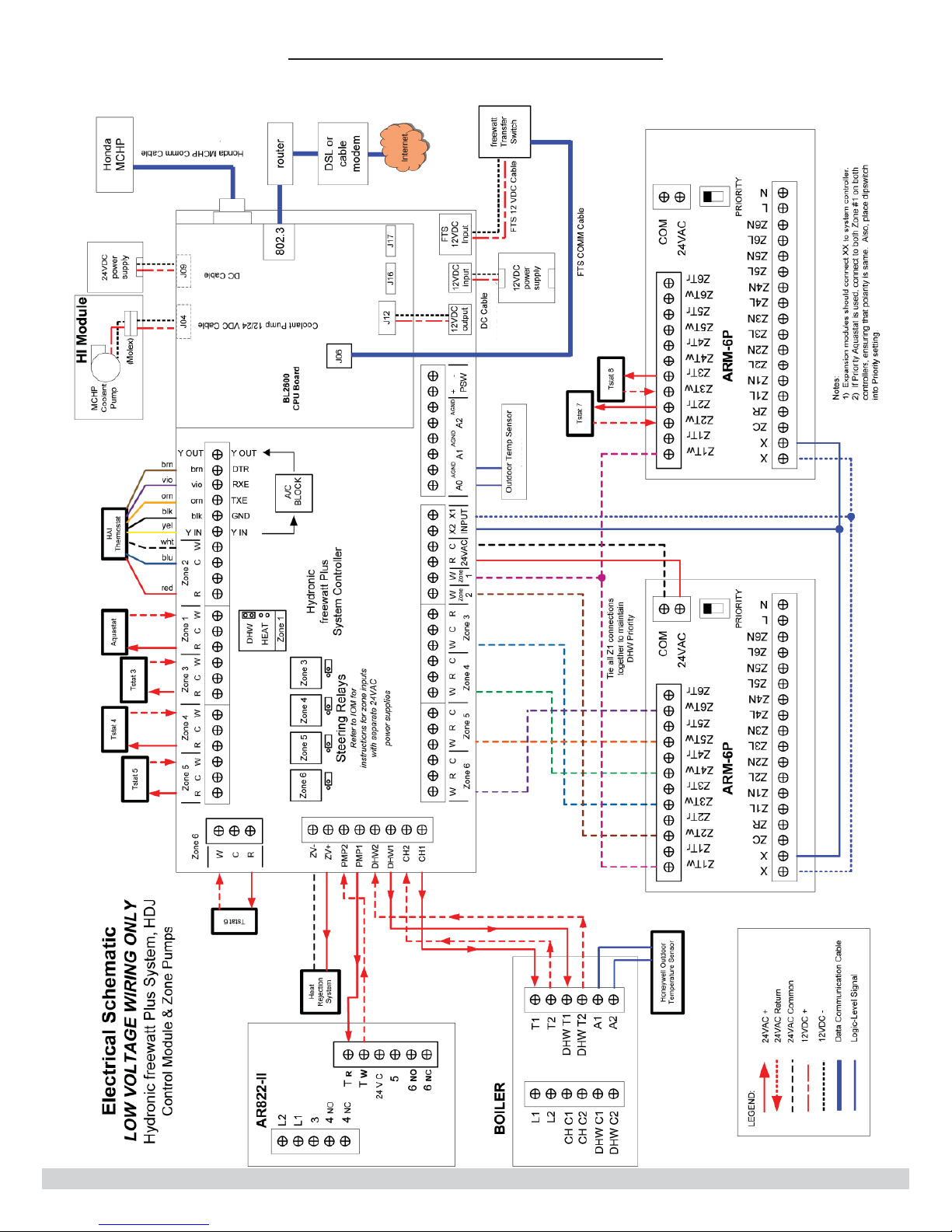
17 - PIPING AND WIRING SCHEMATICS
17-11 HDJ Low Voltage Only Wiring - Control Module and Zone Pumps
63
Page 64
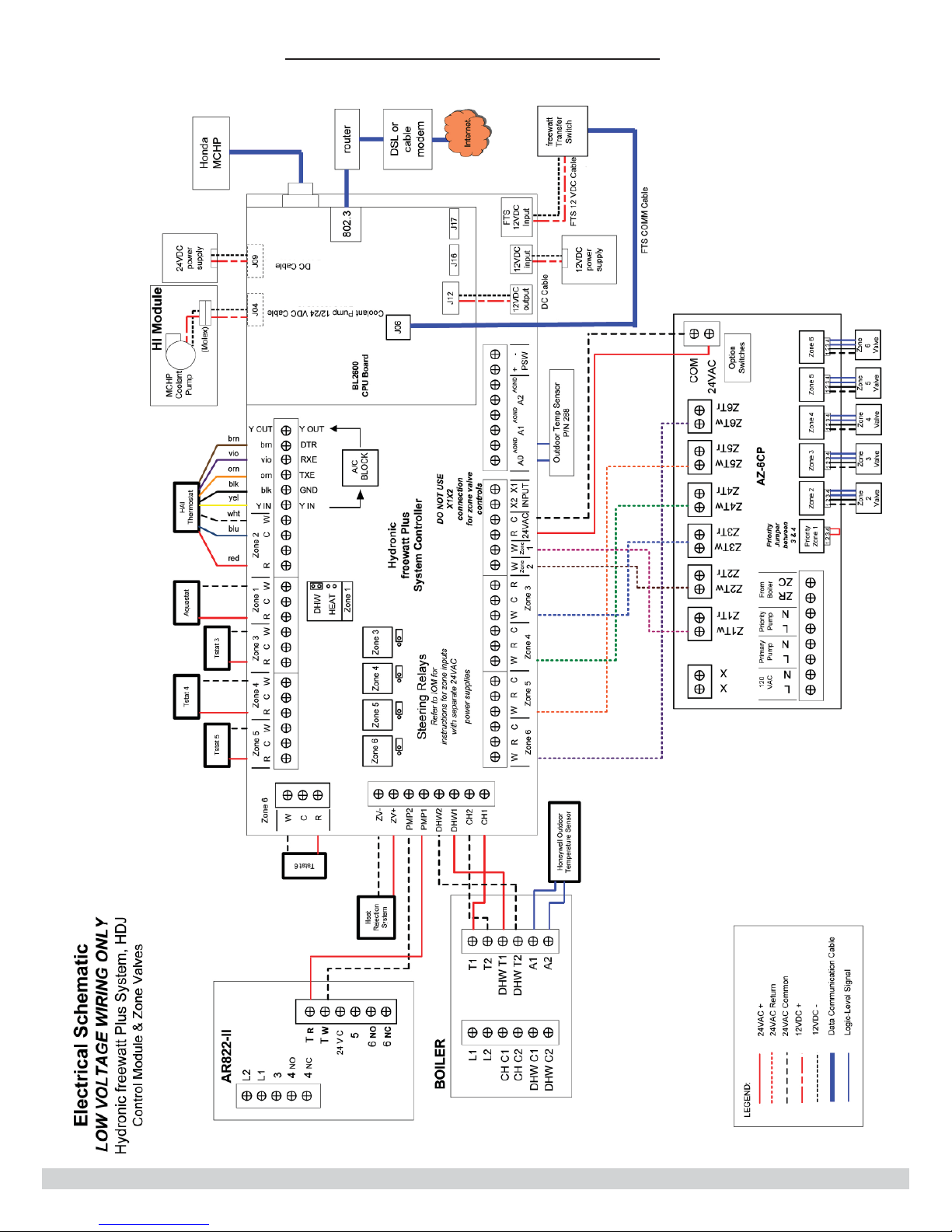
17 - PIPING AND WIRING SCHEMATICS
17-12 HDJ Low Voltage Only Wiring - Control Module & Zone Valves
64
Page 65
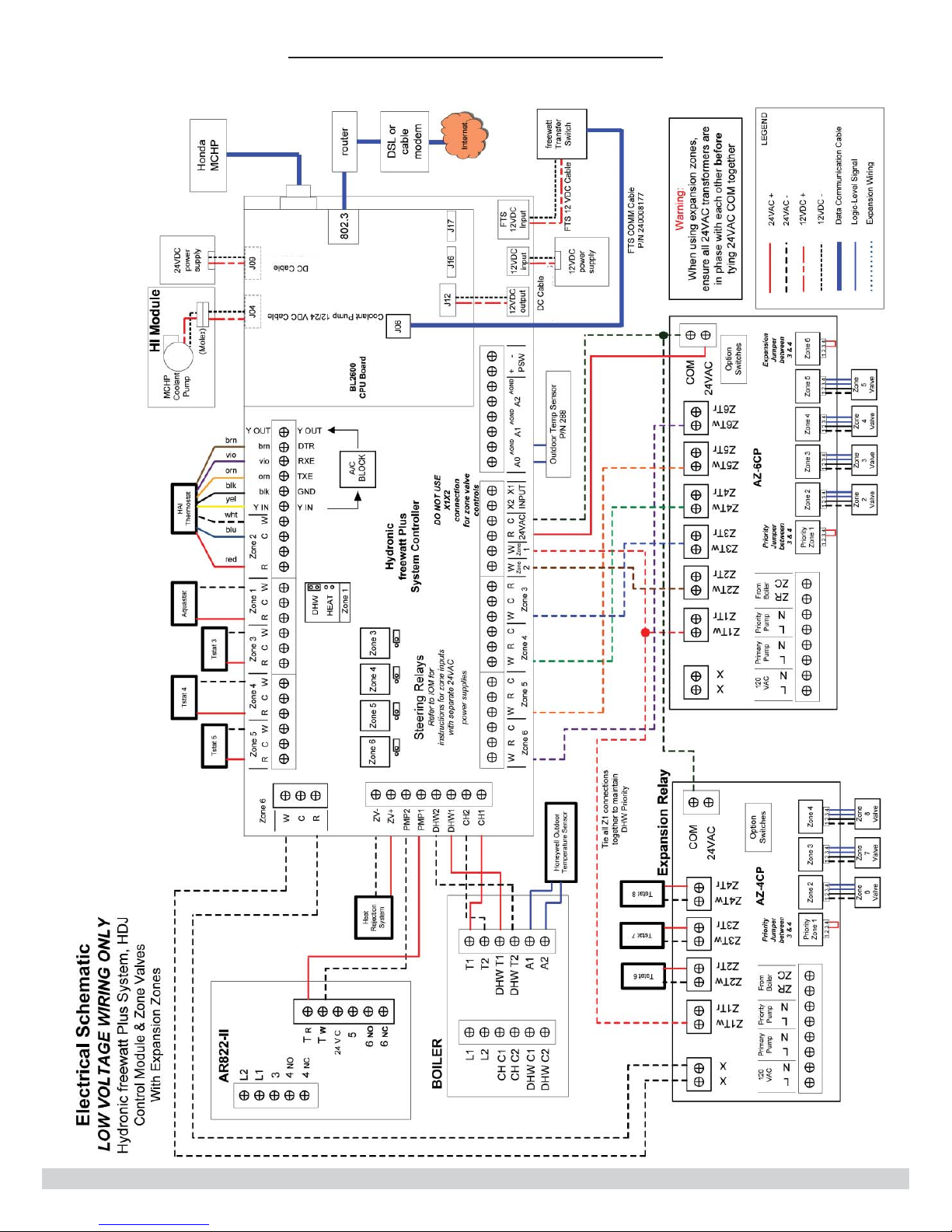
17 - PIPING AND WIRING SCHEMATICS
17-13 HDJ Low Voltage Only Wiring - Control Module & Zone Valves with Expansion Zones
65
Page 66
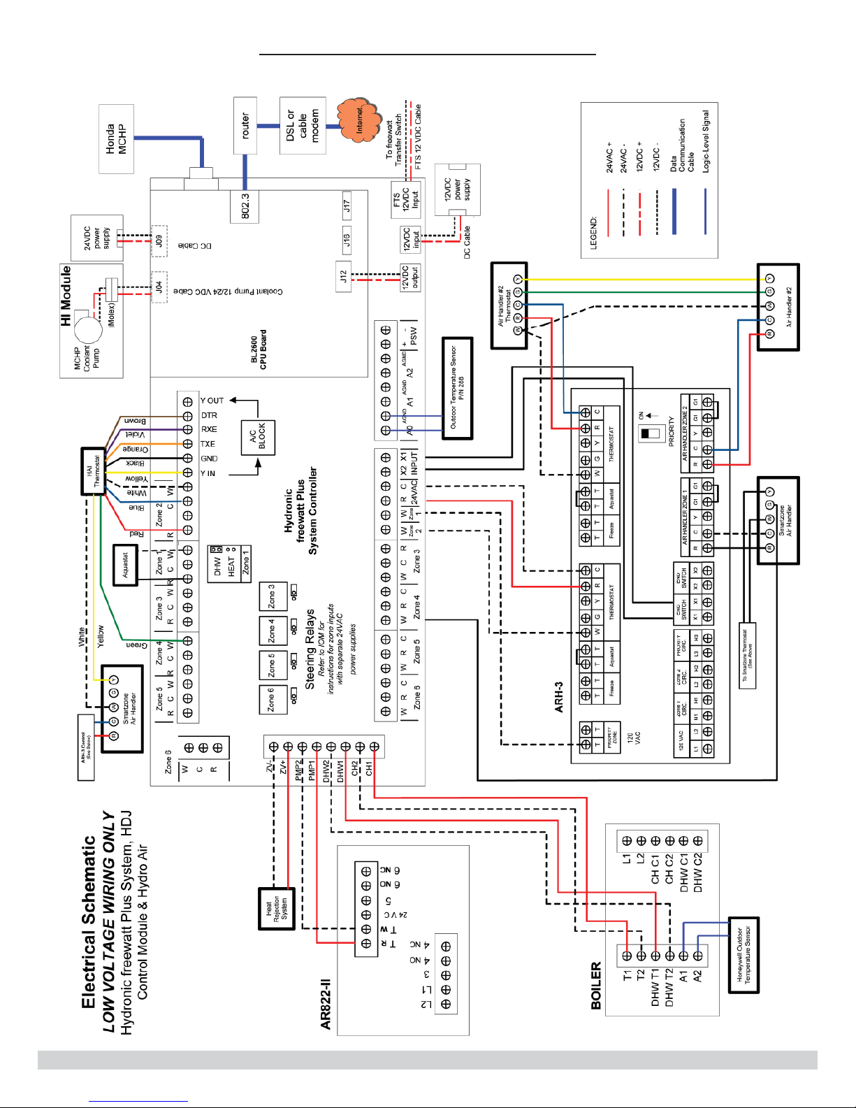
17 - PIPING AND WIRING SCHEMATICS
17-13 HDJ Low Voltage Only Wiring - Control Module & Hydro Air
66
Page 67
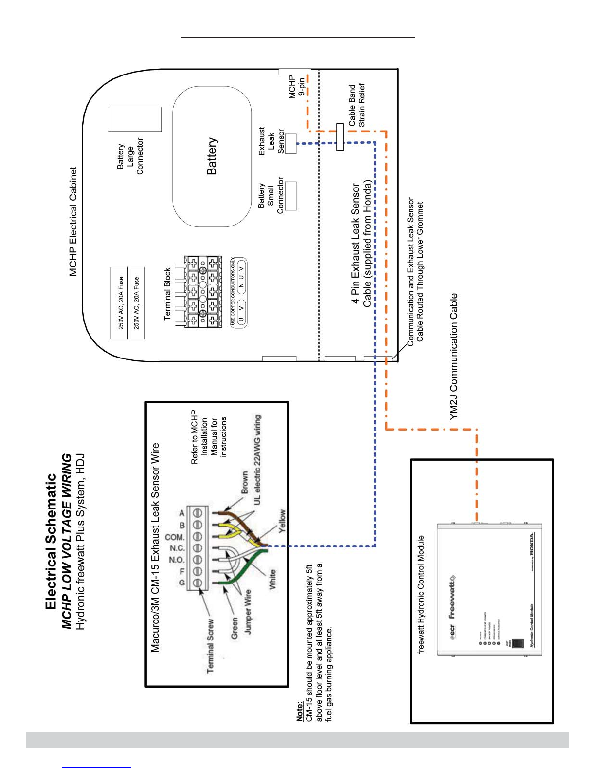
17 - PIPING AND WIRING SCHEMATICS
17-14 MCHP Low Voltage Wiring
67
Page 68

®
Check our website frequently for updates:
www.freewatt.com
www.ecrinternational.com
An ISO 9001-2008 Certifi ed Company
 Loading...