

Page 1
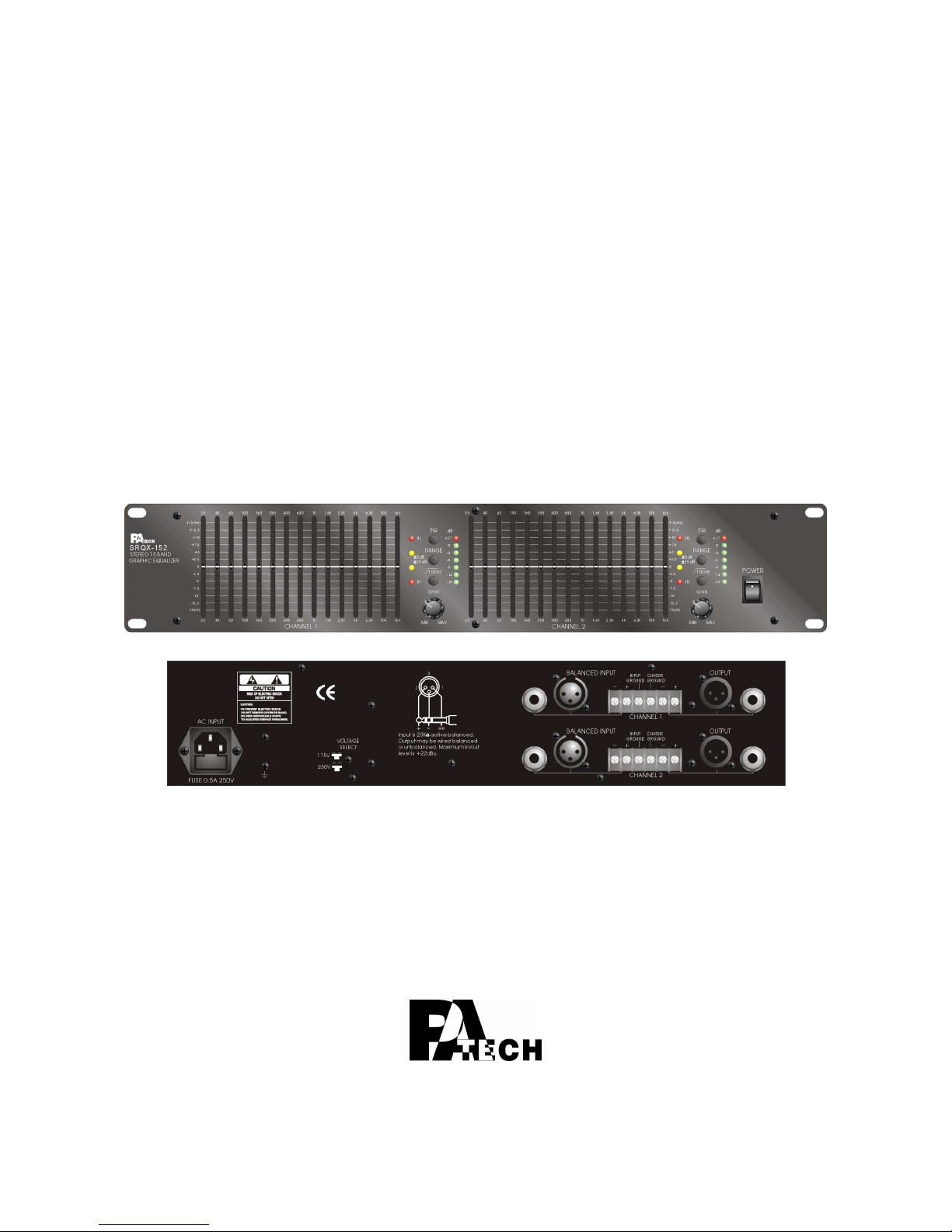
USER MANUAL
Graphic Equalizer
SRQX-152
Page 2
2
1. Security Precautions
◎ Carefully to READ the instruction in this manual before use.
◎ Certainly to OBSERVE the INSTRUCTION in this manual regard convention of safety
symbols and messages
◎ Please KEEP this user MANUAL nearby for anytime reference.
Safety symbol and Message Conventions
Below-described safety symbol and messages are to prevent bodily injury and property
damage. Before operating the graphic equalizer, read this manual first so you completely
knowing the potential safety hazard and understanding the meaning of the safety symbols
and messages.
WARNING
Indicates a potentially hazardous situation, which, if
mishandled, could result in death or serious body
injury, and/or property damage.
CAUTION
Indicates a potentially hazardous situation, which, if
mishandled, could result in moderate or minor body
injury, and/or property damage.
PANEL DESCRIPTION
■ When Installing the Graphic equalizer
DO NOT installing or mounting the graphic equalizer in unstable locations, such as on
the rickety table or the slanted surface. It may result in the graphic equalizer
falling down and causing body injury and/or property damage.
Be sure to ground to the safety ground (earth) terminal to avoid electric shock.
Never to ground to a gas pipe for tragic disaster may occur.
Use the graphic equalizer only with the voltage specified on the graphic equalizer.
Using the voltage higher than specified may cause fire or electric shock.
DO NOT cut, twist, damage, nor modify the power supply cord. In addition, avoid
using the power cord close to heaters, and don’t place heavy object, including
the graphic equalizer itself, on the power cord, for it may cause fire or electric
shock.
DO NOT expose the graphic equalizer to rain or the environment where it may be
splashed by water or other liquids, for doing so, it may cause fire or electric
shock.
WARNING
Page 3

- 3 -
When using the Graphic equalizer
When found following irregular situation during graphic equalizer is in use, immediately
switch off the power, disconnect the power supply plug from the AC outlet. Don’t try to
operate the graphic equalizer again. Contact your local dealer to check the graphic
equalizer.
The graphic equalizer falls.
Graphic equalizer is malfunction.
Water or any metallic object gets into the graphic equalizer.
The smoke or strange smell coming from the graphic equalizer.
The power supply cord is damaged, such as exposure of the core, disconnection etc..
DO NOT put cups, bowls, or other containers with liquid or metallic object in it on the
top of the graphic equalizer. If they spill accidentally into the graphic
equalizer, it may result in fire or electric shock.
DO NOT touch the power supply plug during thundering and lightning, for it may result
in electric shock.
DO NOT insert or drop the metallic objects or flammable materials into the ventilation
slots of the graphic equalizer, for it may result in fire or electric shock.
DO NOT open nor remove the graphic equalizer cover to prevent fire or electric shock,
for there are high voltage components inside the graphic equalizer.
PANEL DESCRIPTION
■ When Installing the Graphic equalizer
DO NOT remove nor plug in the power supply plug with wet hands, for it may cause
electric shock.
When unplug the power supply cord, be sure to grasp the power supply plug. DO
NOT pull on the cord itself. Operating the graphic equalizer with damaged
power supply cord may cause fire or electric shock.
Avoid installing the graphic equalizer in humid or dusty places, the area exposed to
the direct sunlight, locations generating smoke or steam, or the spot near the
heaters. It may result in fire or electric shock.
When moving the graphic equalizer, be sure to remove its power supply cord from the
wall outlet. Moving the graphic equalizer with the power cord connected to
the outlet may cause damage to the power cord, and resulting in fire or
electric shock. When removing the power cord, be sure to grasp its plug to
pull.
DO NOT block the ventilation slots of the graphic equalizer chassis. It will cause the
temperature rising and result in fire.
CAUTION
Page 4

4
■ When Using the Graphic equalizer
Make sure that the volume control is turned to minimum position before power is
switched on. Loud sound produced at high volume when power is switched
on may impair hearing.
DO NOT place heavy objects on the graphic equalizer, for it may cause it fall and may
result in body injury and/or property damage. Besides, the object itself may
cause damaged or body injury.
DO NOT operate the graphic equalizer for the extended period of time with the sound
distorting. It is an indication of malfunction, which can cause heat and result
in fire.
Switch the power off, and unplug the power supply plug from the AC outlet for safety
purposes, when cleaning or leaving the graphic equalizer unused for 7 days
or more. Fire or electric shock may occur.
If the dust accumulates on the power supply plug or in the wall AC outlet, fire may
result in. Clean it periodically. In addition, make sure the plug is inserted in
the wall outlet securely.
Contact your local dealer to clean the dust, it the dust has accumulated in the graphic
equalizer for a long period of time. Dust accumulation may result in fire or
damage.
2. Description
SRQX-152 is 15 band stereo graphic equalizers.
Its input type is “active balanced” and output is “balanced”. It accepts 1/4” phone jack,
XLR, or screw terminal for input and output.
High quality component used makes it is reliable. It is easy to use equalizers.
SRQX-152 is ideal stereo graphic equalizer for general consumer and sophisticated sound
system user.
Page 5
- 5 -
3. Panel Description
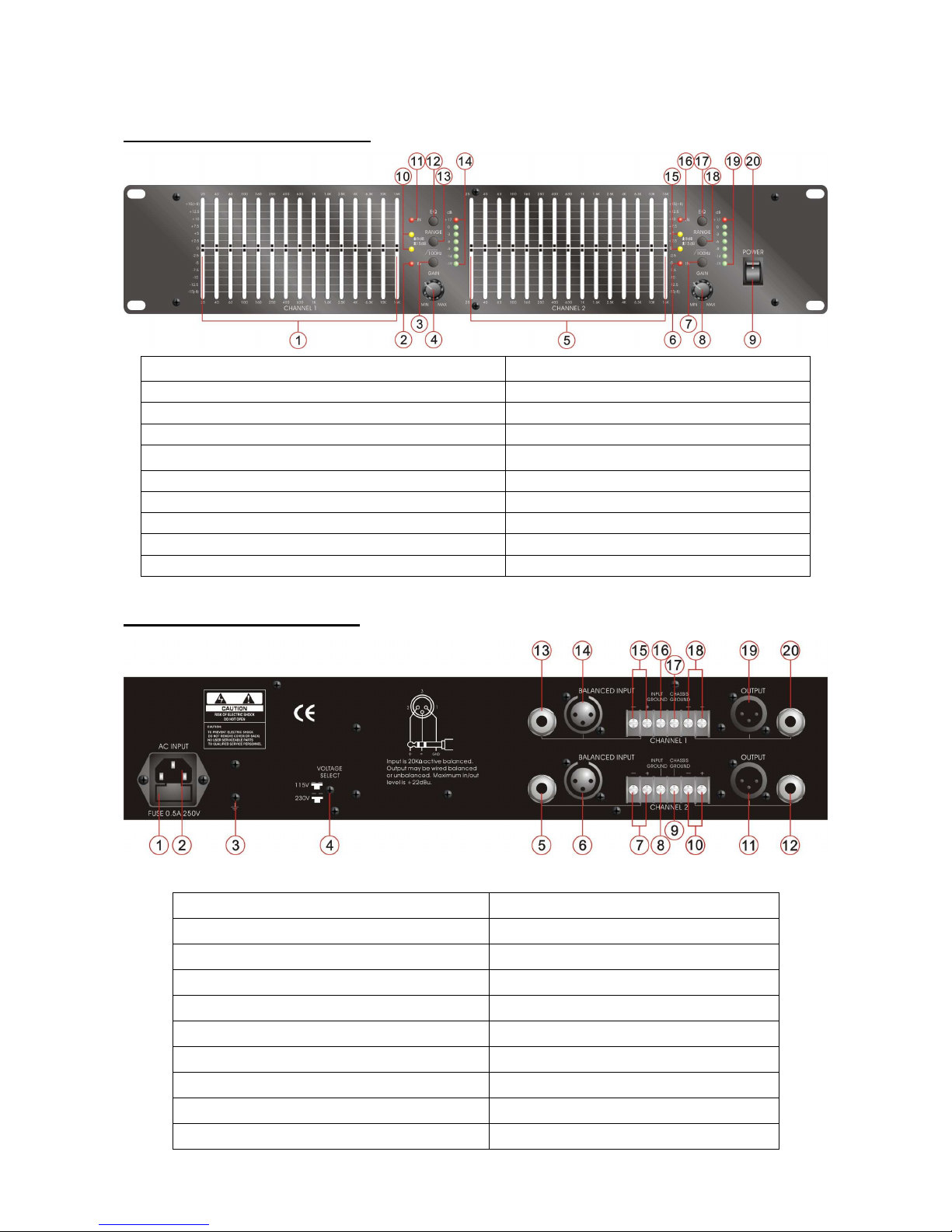
FRONT PANEL DESCRIPTION
1. Channel 1 - Frequency Band Slider Control 11. Channel 1 - EQ Indicator LED
2. Channel 1 - Low Cut Indicator LED 12. Channel 1 - EQ Bypass Switch
3. Channel 1 - Low Cut Switch 13. Channel 1 - Range Switch
4. Channel 1 - Input Gain Control 14. Channel 1 - Input Signal Level LED
5. Channel 2 - Frequency Band Slider Control 15. Channel 2 - Range Indicator LED
6. Channel 2 - Low Cut Indicator LED 16. Channel 2 - EQ Indicator LED
7. Channel 2 - Low Cut Switch 17. Channel 2 - EQ Bypass Switch
8. Channel 2 - Input Gain Control 18. Channel 2 - Range Switch
9. Power Switch 19. Channel 2 - Input Signal Level LED
10. Channel 1 - Range Indicator LED 20. Power Indicator - LED
REAR PANEL DESCRIPTION
1. AC Fuse 11. Channel 2-Output XLR Jack
2. AC Power Input Socket 12. Channel 2-Output Phone Jack
3. Grounding Connection Screw 13. Channel 1-Input Phone Jack
4. Voltage Selection screw Switch 14. Channel 1-Input XLR Jack
5. Channel 2-Input Phone Jack 15. Channel 1-Input screw terminal
6. Channel 2-Input XLR Jack 16. Channel 1-Input ground
7. Channel 2-Input screw terminal 17. Channel 1-Chassis ground
8. Channel 2-Input ground 18. Channel 1-Output screw terminal
9. Channel 2-Chassis ground 19. Channel 1-Output XLR Jack
10. Channel 2-Output screw terminal 20. Channel 1-Output Phone Jack
Page 6

6
4. Features
Two (Stereo) channel 15 band, 2/3-octave Constant Q frequency bands
Active Balanced input
Balanced output
Range cut switch from ±8dB to ±15dB
Frequency Response: 20 Hz ~ 20 KHz ±0.25dB
Front panel control and setting
Input/Output connector: 1/4” phone jack, XLR, and screw terminal
7 Signal Level LED
2U height
5. Power Source
AC Power Source
The supply transformer has been designed for use AC 110V/230V(±10%) 50/60 Hz. One
voltage selection screw switch on the rear for the user to select desired voltage.
6. Connection & Operation
Before connection, make sure the graphic equalizer is off. If possible, remove the
AC power cable until all connections are completed.
Output Connection
Connect all required output devices to the graphic equalizer.
Input Connection
Connect all required input devices to the graphic equalizer. It may include amplifiers
or mixers.
Operation
Turn on the devices in this order: instrument, mixer, signal processor, amps/speakers.
After power is on, set the control and setting to what you desire.
Page 7

- 7 -
7. Control and setting
a. Gain Control – Turn It to control the input signal of each channel.
b. EQ Bypass Switch – Push it down, the equalizer works, and red EQ indicator LED
will light on. When it is up, the equalizer is bypassed, and EQ indicator LED is not
light.
c. Range Switch – When it is pushed down, the equalizer will boost/cut 15db. When
it is up, the equalizer boost/cut 8dB. And only one of two yellow range indicator
LED will light to show it is 8dB or 15dB.
d. Low Cut Switch – When it is pushed down, it will affectively reduce all frequencies
below 100 Hz. The red low cut indicator LED will light to show low cut function is
worked.
e. Frequency Band Slider Control – Each of these slider controls will boost or cut the
corresponding frequency by ±8dB or ±15dB, depending on the setting of the range
switch. All slider are center detent, at which position the corresponding frequency
has a flat response.
Page 8
8
8. Technical Specification
Model
SRQX-152
Power Supply
AC 115/230V 60/50Hz
Input Type
Active Balanced
Input Impedance
10K Ω (Unbalanced)
20K Ω (Balanced)
Output Type
Balanced
Output Impedance
150 Ω (Unbalanced)
300 Ω (Balanced)
Max. Level
+22 dBu
Connectors
1/4" Phone Jack, XLR, Screw Terminal
Crosstalk
<80 dB @ 1K Hz
Subsonic Filter
18 dB/Octave @ 40 Hz
IM distortion
<0.01% @ +20 dBu (Smpte)
Total Harmonic Distortion
<0.01% @ +20 dBu (20 Hz ~ 20K Hz)
Output Hum & Noise
<-92 dBu
Frequency Response
20 Hz ~ 20K Hz +/-0.25 dB
AC Power Consumption
15W @ Rated Power
Dimension
88 (H) x 483(W) x 160 (D) mm
Weight
3.8 KGS
Mounting
19" RACK
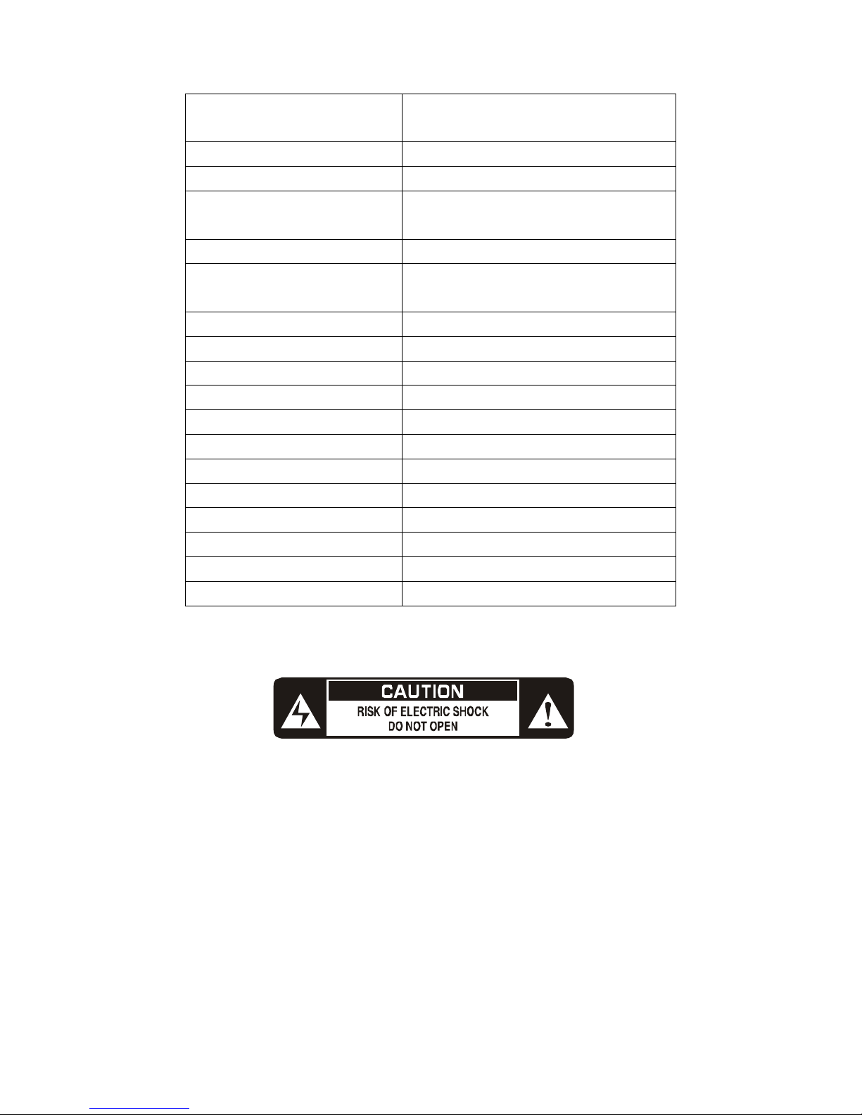
WARNING: THIS APPLIANCE MUST BE EARTHED
 Loading...