


User Guide
2
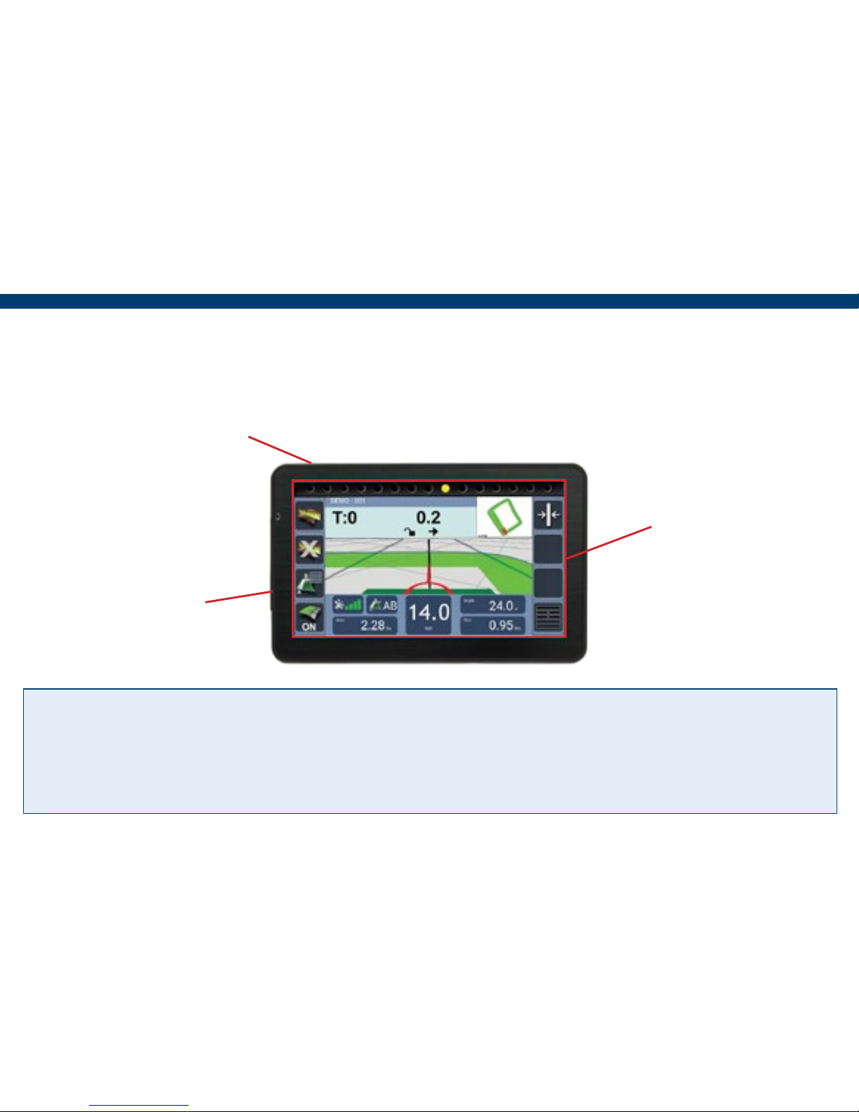
Display
Mount to the windscreen using supplied suction mount and arm.
Warranty Void if suction mount fails !! - It is advised that the suction mount is removed from
the windscreen when the unit is not in operation and reattached on a day to day basis.
For a more permanent xing, a mounting kit that can be secured to the vehicle is available for an
additional cost.
Touch Screen
On/Off button
Mini USB
Charge port
3
Installing the Unit
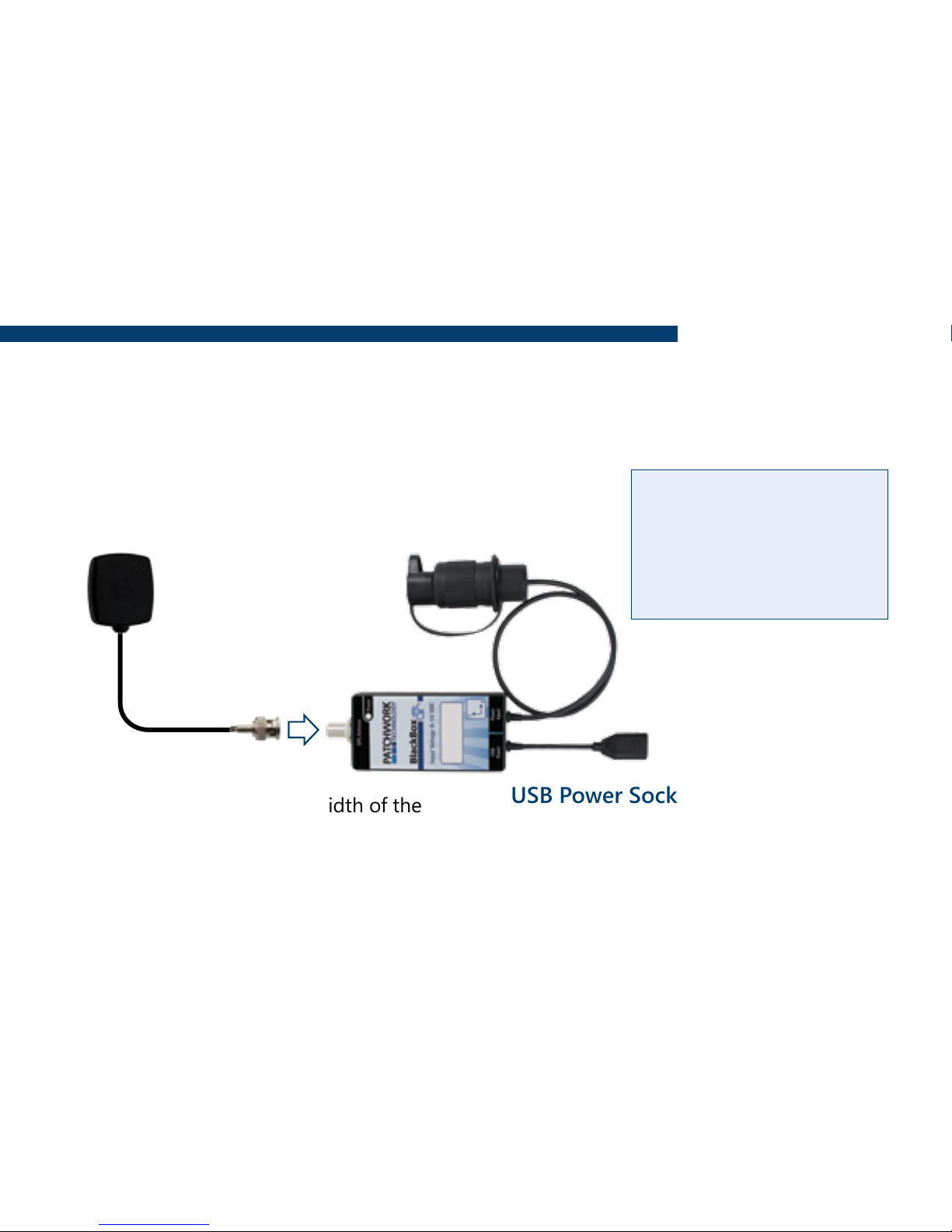
GPS Receiver and Tilt unit
If the tilt function is required, the unit needs to be securely mounted on a at surface with
the ‘Y’ pointing towards the direction of travel.
12v DC Plug
Plug into 3 pin socket on vehicle.
USB Power Socket
Charge the screen via supplied USB Cable.
It is recommended that the charge cable
is always connected to the screen whilst
in use.
Magnetic Antenna
Install centrally across the width of the
roof (if the roof is not metal use the
roof mount plate supplied).
Important!! Completely uncoil the
cable and route around the cab.
Warning - Please
disconnect the unit
from the power supply,
if you need to jump
start your vehicle.
4
Setup
When launching the BlackBox for the rst time the ‘Setup Wizard’ will guide through the
essential settings ready for guidance and area measurement.
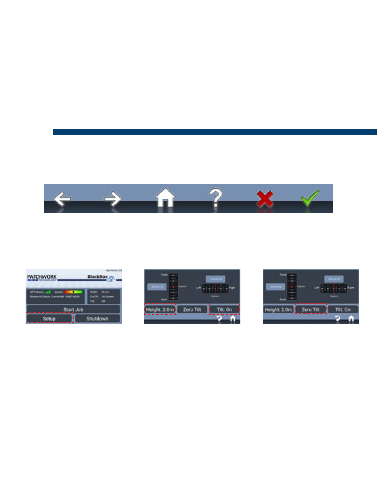
Navigation Bar
Enable Tilt Correction (If required)
Previous Next Home Information Cancel Conrm
N.B. The wizard can be re-accessed via Setup > Unit Setup > Run Initial Setup Wizard.
1) Select Setup > Guidance
Setup > Tilt Compensator
2) Set Tilt to ‘On’, enter
Height, distance from the
ground to the antenna.
3) Position the vehicle on a
known level surface, press
Zero Tilt.
5
Starting a Job
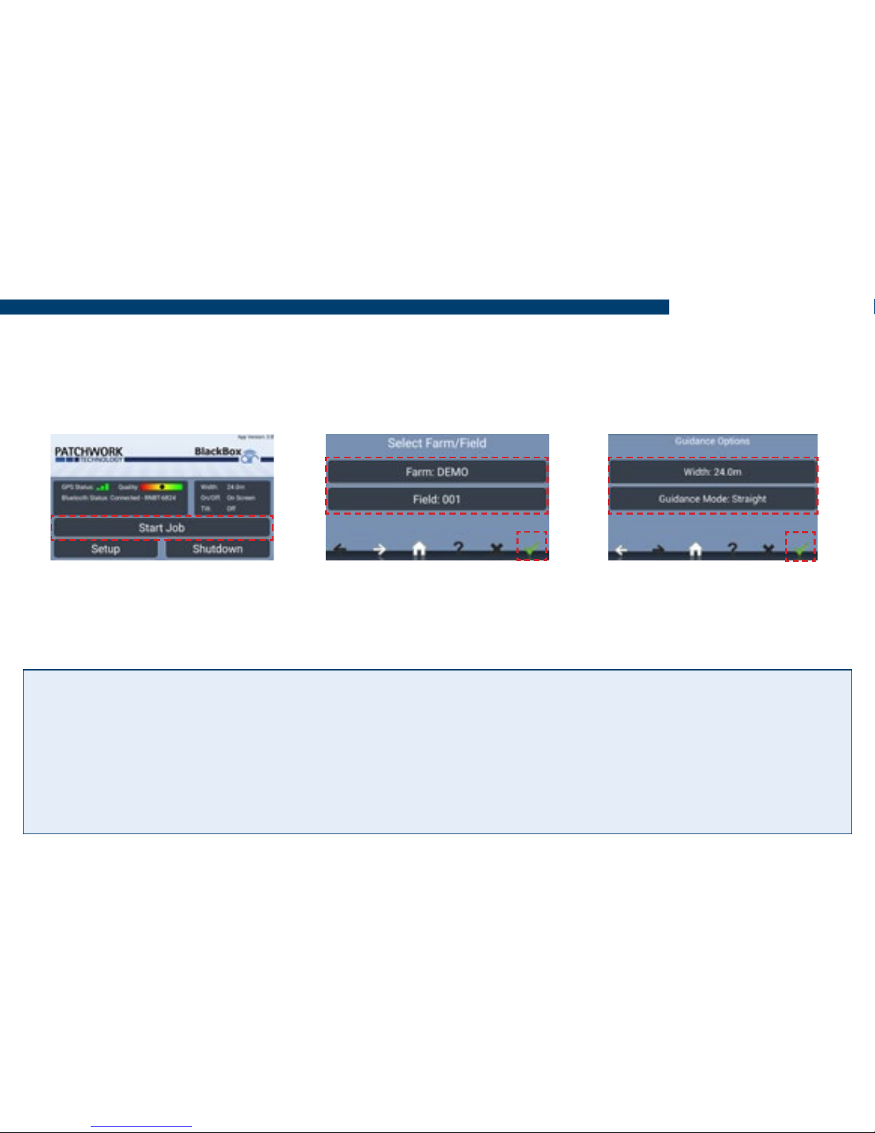
N.B. Before starting a job it is important the correct Bluetooth device is selected and that
the GPS Quality level is within the green. This ensures the best GPS performance for use
with guidance and area measurement.
Guidance Modes
Straight - Sets a straight guidance line between set point A and point B, which is then replicated
both sides of the original line at equal intervals based on the entered width.
Curved - Creates a curved guidance line based on the path driven between set point A and
point B. The line is then replicated both sides of the original line at equal intervals based on the
entered width.
1) Press Start Job. 2) Enter the Farm/Field
name and Conrm.
3) Enter working Width,
select Guidance Mode and
press Conrm to begin job.
6
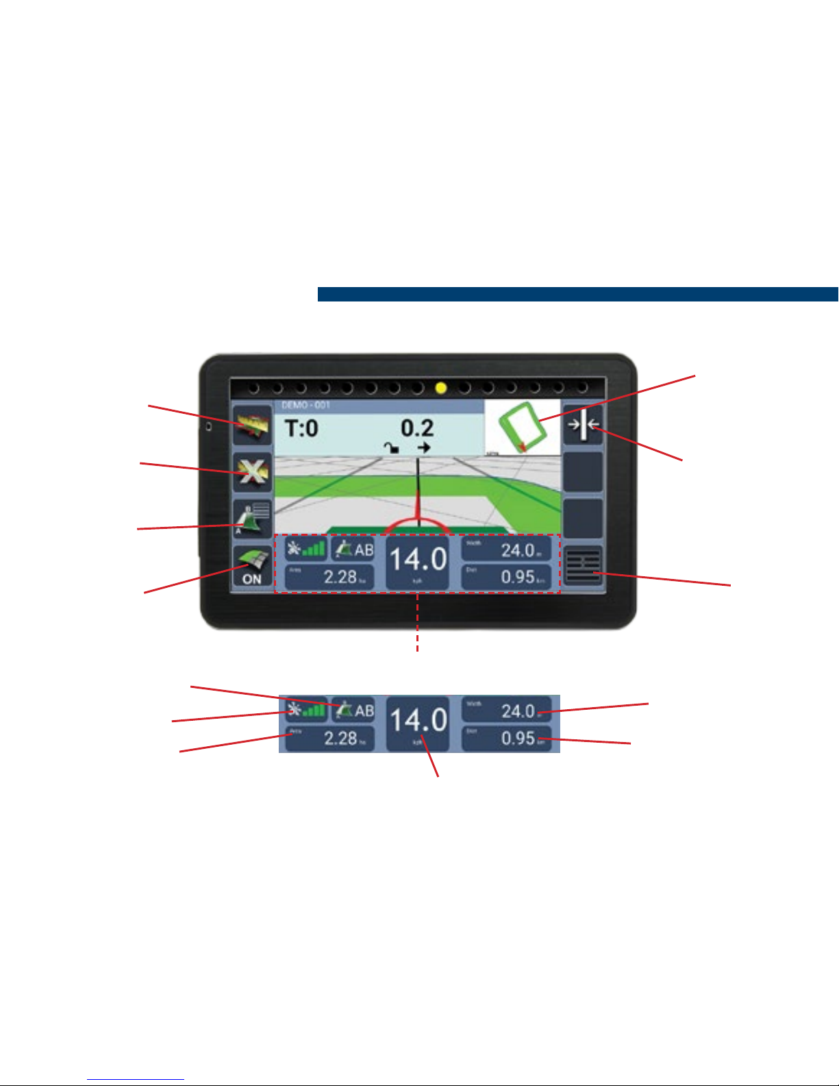
Guidance Screen Overview
Information Panel
Guidance Status
Start/Pause
Boundary
Close
Boundary
Guidance
Options
Recording
On/Off
Menu
Recalibrate
Guidance Line
(Straight Mode
Only)
Mini Map
(Toggle
2D mode)
Working Width
Distance Travelled
Ground speed (Toggle Speedometer /Digital)
GPS Strength
Coverage Area
7
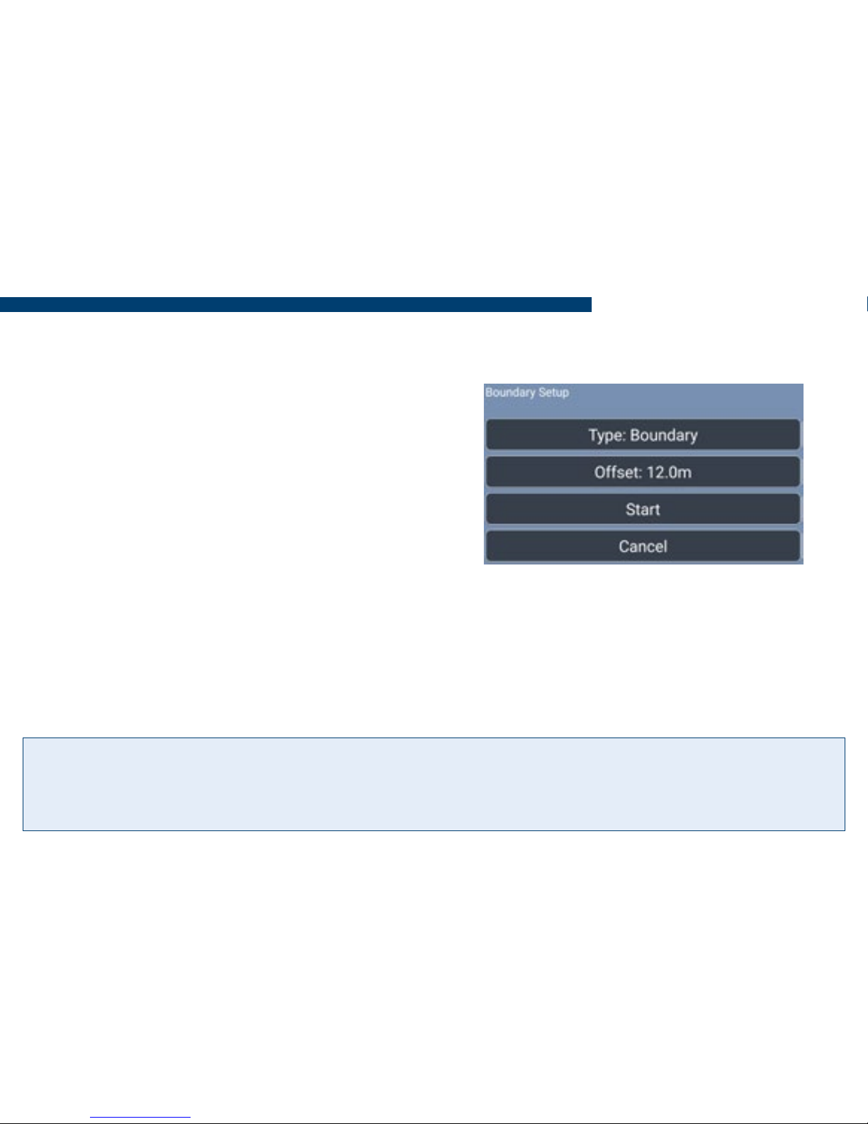
Measuring Field Area
1) After starting a new job, position your vehicle at the edge of the eld and press Start/
Pause Boundary.
2) Set Type to Boundary
3) Set the Offset to the distance from the
antenna to the edge of the eld.
4) Press Start and drive around the eld until
the start point is reached. The BlackBox will
automatically close and save the boundary map,
displaying the eld shape and size in the mini
map. If the boundary doesn’t close, press the
Close Boundary button.
N.B. During the boundary run the boundary recording can be paused and restarted using
the Start/Pause Boundary button, if there is a need to drive around obstacles.
To do a new boundary map redo steps 1) to 3).
Tip! Boundaries are saved to the system using the Farm/Field name entered when ‘Starting a Job’
and the next time the eld is entered the system will Automatically Detect the eld, displaying it
in the Home screen.
8
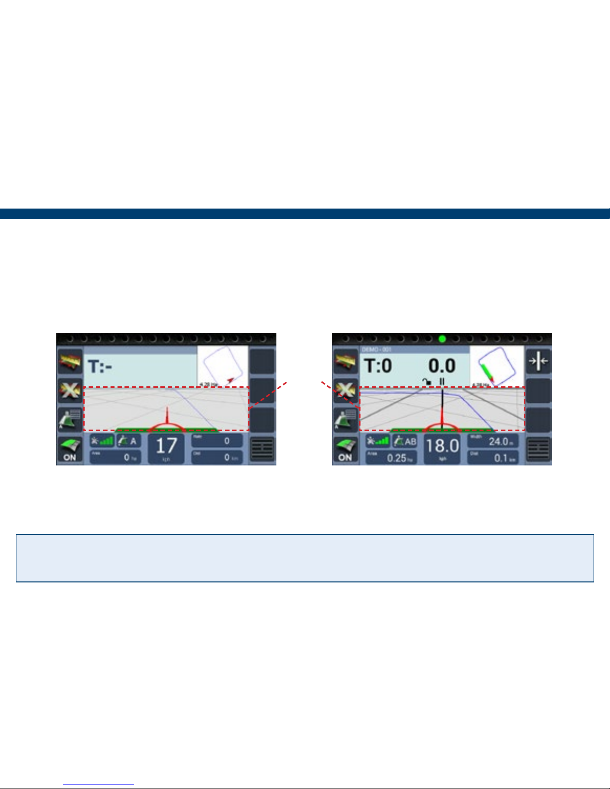
2) At the beginning of a straight run
press the Grid area to set point A.
3) Drive to the end of the run and press
the Grid area to set B. The guidance
line will appear ready for guidance.
N.B. The green coverage recording can be turned off and on using the ‘Recording On/Off’
button if ‘On Screen’ has been set.
1) Position the vehicle in the eld where the job will begin. (When using a curved line it is
important to use the longer edge of the eld to set a guide line).
Tip! Pressing the Grid area a third time allows the guidance line to be reset and if using the
‘Straight’ guidance mode, recalibrated to realign with current location.
Grid
area

9
Setting and Using a Guidance Line
4) If working the headland pass,
continue around then line up to the set
AB line and use the guidance to work
the inner areas of the eld.
5) When turning in the headland the
next AB line will appear.
To complete a eld boundary map or guidance job to start a new one, press the Menu
button and then Next Job to do a different job with the same settings or Finished Job to
return to the Home screen.
To power off the BlackBox press Shutdown, then press Yes and disconnect from power
supply.
Finishing a Job

10
Pause Job
The following setup instructions are exclusive to Air+ software users, the
Air+ software is a paid for upgrade which is available to all BlackBox Air
users and includes the following features :- Pause Job | Auto Record |
Headland Guidance | Headland Warning | Tracking | Boundary Printing
Resuming a Paused job
If a pause job is available, press Start Job an option box will appear with the option to
continue the paused job. Pressing Yes will resume the job with a red marker in the mini map
to show where the job was paused.
1) When in the Job screen, Press
Menu.
2) Press Pause Job, this will save the
coverage area and any guidance lines
that were set.

11
Air+ Features
Auto Record
Auto record automatically turns the coverage recording OFF when 75 percent of the
working width goes inside a previously recorded area and turns back ON when 25 percent
of the working width is outside the recorded area.
1) On the Home screen, press Setup.
3) Select On/Off, choose Auto
Record from the list and press OK.
2) Then press Guidance Setup.
4) Press Home, Auto record is set
ready to begin a job.

12
Headland Guidance
Headland guidance uses an existing Field Boundary Map to create a guidance line based on
the working width. This guidance line is to guide the user when working the headland of the
eld.
1) When in the job screen with the
Field Boundary loaded, press in the
area as shown above.
3) To switch back to AB guidance
press on ‘H:’.
2) The headland guidance line will
appear indicated by ‘H:’, ready to
guide.
Tip! Alternatively Headland Guidance
can be activated in Guidance Options
by selecting Headland and deactivated
by selecting Track.

13
Air+ Features
Headland warning creates a headland zone from the eld boundary map at a distance
specied by the user as the ‘Headland Size’. As the user approaches the edge of the zone a
distance counter will countdown to zero alerting the user to stop or start the implement.
1) On the home screen, press
Setup > Guidance Setup.
2) Press Antenna Offset, then
tick and select A
3) Enter the distance from the antenna
to the working part of the implement.
4) Press Home, then Setup > Air+
Setup > Headland Warning Setup.
Headland Warning

14
7) Headland Distance Off / Headland
Distance On, these can be set to alert
the user earlier, i.e. if 2 metres is entered
the user will be alerted 2 metres before
the edge of the zone.
8) Press Home, Headland
Warning is now setup ready to
begin a job.
5) Press Headland Warning
and select Enable
6) Press Headland Size and
enter the distance required.

15
Air+ Features
Using in the Job Screen
N.B. A eld boundary map needs to be created for the eld.
The headland zone edge
is displayed as a Red Line
in the 2d mini map.
When the user drives in and out of the headland, a countdown starts at 25m, when 0 is
reached the green bar will change to white. This is the point the implement should be
turned on or off depending on the current state.

16
N.B. A BlackBox Core account is required to utilise this feature, for more information call
+44 (0) 1291 673366.
Using a mobile phone as a Wi-Fi hot spot (not required if the android device has mobile
data capability), the tracking feature connects via Wi-Fi to the mobile phone and uses the
mobile data to send positional data to BlackBox Core PC software. Within Patchwork Core
the tracking data can be displayed to show the current position of the BlackBox and where it
has been.
1) On a Mobile Phone that has mobile data access, enable the phone to be used as a Hot
Spot (refer to the mobile user guide for instructions) and make a note of the access code.
Tracking
2) On the BlackBox home screen,
press Shutdown > Yes.
3) Press Android Setup.

17
Air+ Features
4) Enable Wi-Fi. Choose the name
of the hotspot and enter the access
code. Once connected press Home
and then Start BlackBox Air.
6) Press Tracking and then Enable.
5) When the BlackBox has loaded
press Setup > Air+ Setup.
7) Press Home, the BlackBox is now
sending positional data to Patchwork
Core, so it can be tracked.
Warning!! This feature requires a mobile data connection and will reduce the available
usage of the mobile data plan.

18
Boundary Printing
N.B. BlackBox Core can be used to store, view and print boundary maps, for more
information call +44 (0) 1291 673366. Alternatively they can be printed using a PC via the
following method :-
1) Once the boundaries to be printed have been mapped (as per ‘Measuring Field Area’)
take the tablet and USB cable to a Windows PC.
2) Fit the USB cable into a spare slot on the PC and ensure the other side is connected to
the tablet.
3) With the tablet power on, navigate
to the BlackBox Air+ home screen.
4) Using your nger swipe down in
the top left of the screen to display
the Android navigation bars.

19
Air+ Features
5) Swipe down in the top left a
second time to display the USB
options and from the list press on
USB Connected.
7) On the PC in most cases it will
automatically detect the storage device
(tablet storage drive) and open it
automatically to display the folders, if
not open windows explorer and locate
the storage device drive.
6) An app called ‘Android USB Mass
Storage’ will open, press Turn on USB
Storage and press OK to the message box.
Tip! Files can also be copied from the DCIM folder to a folder on the PC for storage and backup.

20
8) Locate the folder labelled ‘DCIM’
and open it. All the boundaries that
are printable will be stored here.
9) To print the boundaries, right mouse
click on the le or select multiple les and
right click one of them and from the drop
down menu click Print.
11) Once the required boundaries have
been printed, on the Tablet press ‘Turn
off USB storage’ and disconnect the USB
cable from the PC.
10) Choose your printing preferences
and click Print.
Air+ Features

21
Troubleshooting
Problem Cause Solution
Bluetooth not
connecting
No power to the GPS
Receiver and tilt unit
Ensure the unit is connected to a working
power source.
Screen and Receiver did
not connect during start
up
Disconnect GPS receiver and tilt unit from
power source, power off the Android
tablet. Re-power the GPS Receiver.
The tablet and GPS
receiver have become
‘Unpaired’
From the BB Air Home screen, press
Shutdown > Yes, select Android Setup,
open Bluetooth options, ensure Bluetooth
is enabled, locate the device under
available devices, select it and then Pair.
Once repaired press home and launch
BlackBox Air.
No GPS Signal Obstructions are causing
the antenna not to pick
up signal
Ensure the antenna in its current position
has a clear view of the sky.
GPS Receiver not
powered
Check the power LED is lit and it is
connected to the power source.

22
Problem Cause Solution
Guidance off to
the one side
Left or right antenna
offset has been set
Go to Setup > Guidance Setup > Antenna
Offset, set the B to 0m.
Interference due to other
radio equipment
Mount the antenna in a different location
and retry.
Antenna cable coiled
tightly
Uncoil and route around Cab.
Tilt not calibrated /
mounted correctly
Ensure mounted correctly see ‘Installing
the Unit’, then Go to Setup > Guidance
Setup > Tilt Compensator and Zero Tilt
when on a at surface.
Screen powering
down.
Charge lead not
connected
Ensure the USB charging lead is connected
via the USB power socket of the Screen
and the Receiver.
Coverage area
not working
The coverage area On/
Off method is not set
correctly
Go to Setup > Guidance setup > On/Off
and choose the option required.

23
Troubleshooting
Problem Cause Solution
Guidance line
not displaying
correctly
Using curved guidance
and the line has been set
to short
When setting a curved line ensure that it
is set on the longest edge in the eld and
the full length of the run.
In Headland Guidance
mode ‘H:’ displayed.
Press the H: to toggle back to AB track
guidance.
Notes

Patchwork Technology Ltd. Oaklands, Llancayo Court,
Llancayo, Usk, Monmouthshire, NP15 1HY
+44 (0)1291 673366
 Loading...