

Page 1
Attaching the External Antenna
Installation Guide
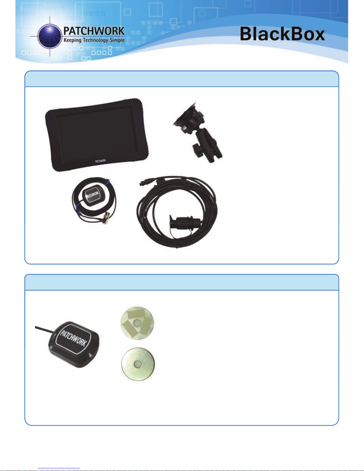
Contents
Warning – Please disconnect the unit from the power
supply, if you need to jump start your vehicle.
PWdoc0007 rev.2.3
PWdoc0047 v1.2
Attach the antenna to the roof of the vehicle,
positioned centrally across the vehicles width.
For non metal roofs use the supplied metal plate
by firstly cleaning the area and ensuring it is dry,
then remove the plastic covers from the self
adhesive strips on the metal plate and stick to the
vehicle roof. The antenna can be attached to this
plate and be held safely on the roof.
Run the cable into vehicle cab, if going through a window or door please make sure that there
is enough of a gap in the rubber to allow this, otherwise the cable could be damaged and with
no signal from the antenna the BlackBox will not function correctly.
1) BlackBox Unit with SD card
2) Antenna
3) Power Lead
4) Ram arm and mount
1)
2)
4)
3)
Page 2
PWdoc0007 rev.2.3
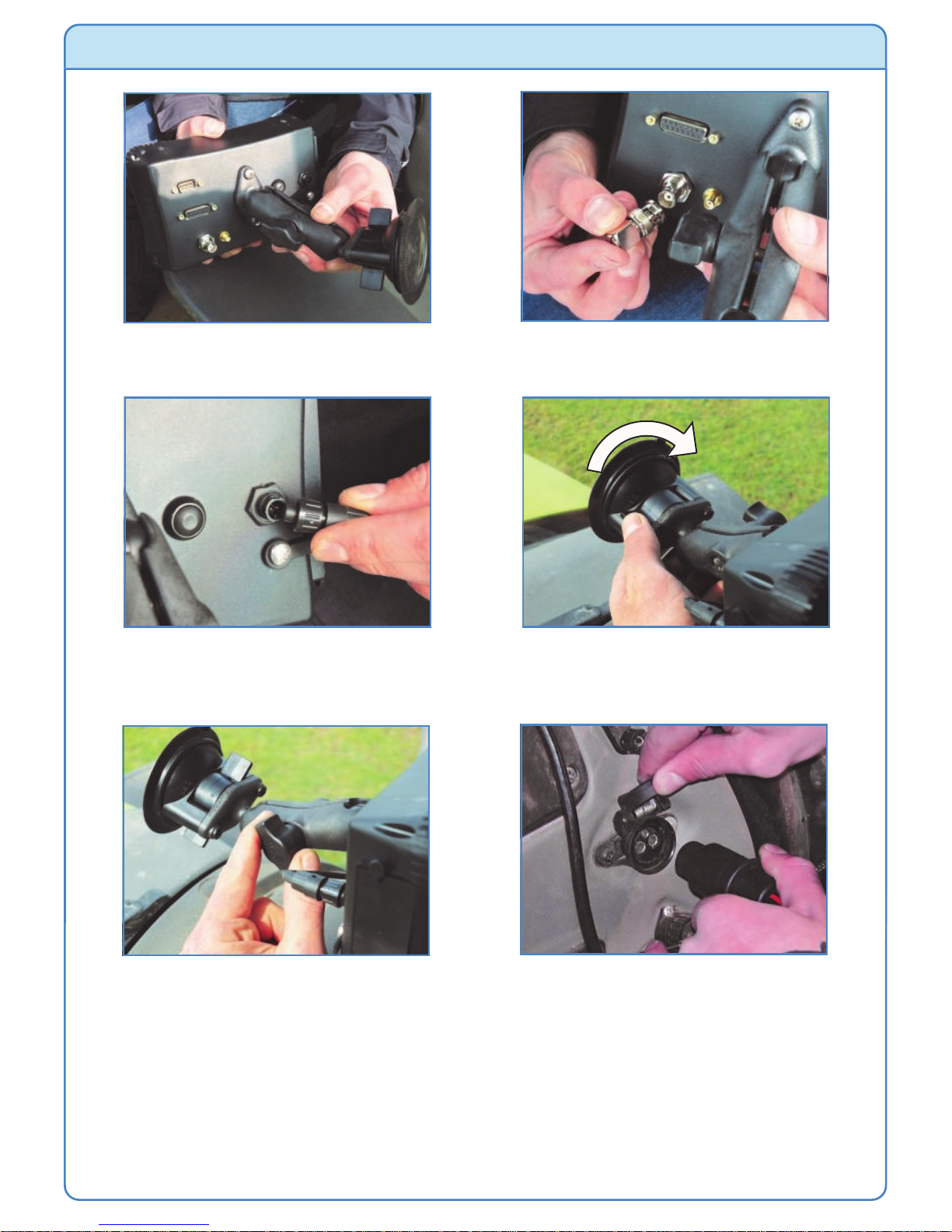
Fitting in the Vehicle
Warranty Void if suction mount fails !! - It is advised that the suction mount is
removed from the windscreen when the unit is not in operation and reattached
on a day to day basis.
For a more permanent fixing please detach the ram ball from the suction mount and
secure down in the vehicle.
1) Attach the RAM arm to the ball on the
back of the BlackBox unit.
2) Connect the antenna plug to the
connector of the unit.
3) Plug and screw in the power lead
connector. Be sure not to over tighten.
4) Push the suction mount on to the
windscreen and turn the lever from the
off to on position.
5) Tighten the screw on the arm to secure
in position. Ensure the unit is level and
square to the windscreen if using tilt.
6) Connect the 3-pin plug of the power
lead to the vehicle power supply. The
unit will power up automatically.
Page 3

Connecting to the Auto Steer System
Connecting a switch to control coverage area
Ref Description Part No.
1 Boom Sense Cable 03-05-0015
2 Switch (request when ordered) N/A
3 Relay (request when ordered) N/A
* The relay option uses the voltage
feed which is inline with the
implements main on/off switch to
control the coverage area recording.
See above diagram for connections.
The BlackBox will need to be configured to work
correctly with the switch, for details see Ports Setup
menu ‘On/Off’ in the Operating Instructions.
Ref Description Part No.
1 Evolution Cable 03-05-0039
2 BlackBox Evolution Kit Various
The BlackBox will need to be configured to work
correctly with the auto steer system, for details see
Advanced menu ‘Steering’ in the Operating
Instructions.
To 15-way
connector
To power
connector
To connector
on ECU
To 3-Pin
connector
in vehicle
To 15-way
connector
1
2
3
1
2
Page 4

System Maintenance
Changing the Fuse
Warning !! - Before beginning the following procedure, disconnect the unit
from the power source.
Cleaning the unit
The outside surfaces of the unit can be cleaned with a damp (well rung out) lint free
cloth. Please allow the unit to dry fully after cleaning before powering the unit on
again.
Updating the software
Patchwork are continually improving the BlackBox software through improved
usability and adding new features.
The updates are free to BlackBox users and can be obtained by taking the SD Card
supplied with the unit, to a computer with internet access. Using an internet browser
go to www.patchwork.co.uk/support_updates_blackbox.aspx and follow the
onscreen instructions.
Important !! - Storage when not in use
If the unit is not going to be used for a long period of time, it is best to remove the
system from the vehicle and store safely in a dry safe location inside your home or
workshop.
2) Remove the fuse from the fuse holder
and replace with a ‘2A’ standard blade
fuse. Refit the fuse holder lid.
1) Gently prise open the fuse holder lid.
 Loading...