

Page 1
© 1996-2001 by PAT GmbH ∙ D-76275 Ettlingen ∙ Hertzstr. 32 - 34 ∙ ++49 (0) 7243 709-0 ∙ FAX ++49 (0) 7243 709-141 1
19_1272E.DOC / 2001-04-02 / Rev. C / ko.
The information in this document is subject to change without notice. PAT makes no warranty of any kind with
regard to this material, including, but not limited to, the implied warranties of merchantability and fitness for a
particular purpose. PAT shall not be liable for errors contained herein or for identical or consequential damages
in connection with the furnishing, performance, or use of this manual. This document contains proprietary information which is protected by copyright. All rights reserved. No part of this document may be photocopied, reproduced, or translated to another language without the prior written consent of PAT.
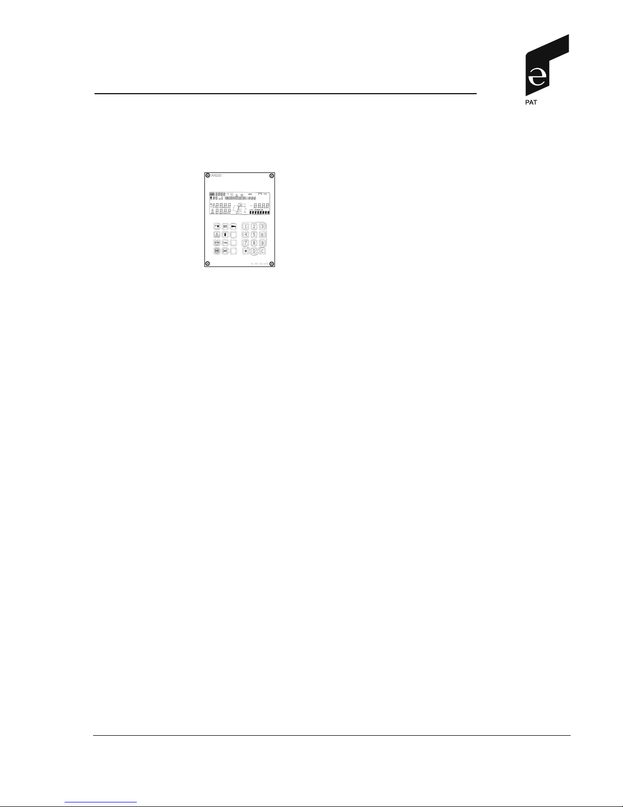
USER MANUAL
IK 350 / 1272
part no. 50 350 19 1272 e
Page 2

© 1996-2001 by PAT GmbH ∙ D-76275 Ettlingen ∙ Hertzstr. 32 - 34 ∙ ++49 (0) 7243 709-0 ∙ FAX ++49 (0) 7243 709-141 2
19_1272E.DOC / 2001-04-02 / Rev. C / ko.
TABLE OF CONTENTS
1. General Information ................................................................ 3
2. Warnings .................................................................................. 4
3. System Description ................................................................. 5
3.1 System Function........................................................................ 6
3.2 Operator's Console.................................................................... 6
3.3 Control Identification.................................................................. 7
3.4 Data Display ............................................................................ 14
4. Programming ......................................................................... 18
4.1 Setup Operation Mode ............................................................ 18
4.2 Setup Reeving ......................................................................... 19
5. Pre-Operation Inspection and Calibration verification ...... 20
5.1 Operation................................................................................. 22
6. Service and Maintenance...................................................... 23
7. Troubleshooting .................................................................... 24
7.1 General.................................................................................... 24
7.2 System messages ................................................................... 24
7.3 Error Code Table ..................................................................... 25
Important Notes for crane operators and users .......................... 36
Page 3

General Information
© 1996-2001 by PAT GmbH ∙ D-76275 Ettlingen ∙ Hertzstr. 32 - 34 ∙ ++49 (0) 7243 709-0 ∙ FAX ++49 (0) 7243 709-141 3
19_1272E.DOC / 2001-04-02 / Rev. C / ko.
1. GENERAL INFORMATION
This manual describes the function, operation and maintenance of the DS 350 Load Moment Indicator
1
(LMI).
The LMI has been designed to provide the crane operator with the essential information required to
enable the machine to be used within its design parameters.
Using various sensing devices, the Load Moment Indicator monitors various crane functions and provides the operator with a continuous reading of the crane's capacity. The readings continuously
change as the crane moves through the motions needed to make the lift.
The LMI provides the operator with information regarding the length and angle of the boom, tip height,
working radius, rated load and the total calculated weight being lifted by the crane.
If non permitted conditions are approached, the DS 350 Load Moment Indicator will warn the operator
by sounding an audible alarm, lighting a warning light and locking out those functions that may aggravate the crane's condition.
1
LOAD MOMENT: generally the product of a force and its moment arm; specifically, the product of the load and the load-
radius. Used in the determination of the lifting capacity of a crane.
Page 4
General Information
© 1996-2001 by PAT GmbH ∙ D-76275 Ettlingen ∙ Hertzstr. 32 - 34 ∙ ++49 (0) 7243 709-0 ∙ FAX ++49 (0) 7243 709-141 4
19_1272E.DOC / 2001-04-02 / Rev. C / ko.
2. WARNINGS
The LMI is an operational aid which warns a crane operator of approaching overload conditions and
also warns of overhoist conditions which could cause damage to equipment and personnel.
WARNING
The device is not, and shall not, be a substitute for good operator judgment, experience and
use of accepted safe crane operating procedures.
The responsibility for the safe operation of the crane shall remain with the crane operator
who shall ensure that all warnings and instructions supplied are fully understood and observed.
Prior to operating the crane, the operator must carefully and thoroughly read and understand the information in this manual to ensure that he knows the operation and limitations
of the indicator and crane.
Proper functioning is dependent upon proper daily inspection and observations of the operating instructions set forth in this manual.
WARNING
The displays will only aid the operator when the LMI is properly programmed and the proper
load capacity chart is selected for the crane configuration being utilized. To prevent property damage or serious bodily injury or death to personnel, ensure the LMI is properly programmed before operating the crane.
WARNING
This system is equipped with an override key on the central microprocessor unit. This key
switch bypasses control lever lock-out function of load moment indicator device. The
switch may only be used by authorized personnel during emergency situations. Failure to
follow this instruction may result in property damage and/or personal injury.
Page 5
System Description
© 1996-2001 by PAT GmbH ∙ D-76275 Ettlingen ∙ Hertzstr. 32 - 34 ∙ ++49 (0) 7243 709-0 ∙ FAX ++49 (0) 7243 709-141 5
19_1272E.DOC / 2001-04-02 / Rev. C / ko.
3. SYSTEM DESCRIPTION
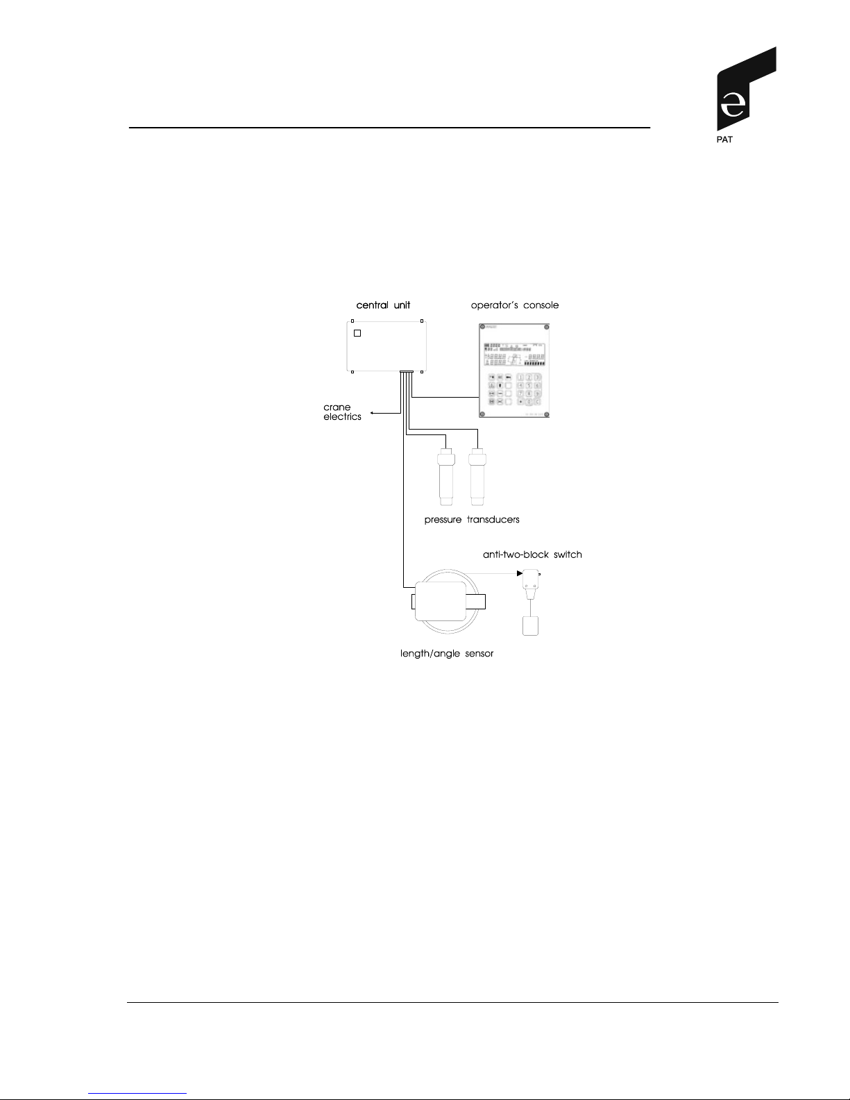
The PAT Load Moment Indicator DS 350 consists of a central micro processor unit, operating console
and various peripheral sensors.
The system operates on the principle of reference/real comparison. The real value, resulting from the
pressure measurement is compared with the reference data, stored in the central processor memory
and evaluated in the micro processor. When limits are reached, an overload warning signal is generated at the operator's console. At the same time, the dangerous crane movements, such as hoist up,
telescope out and boom down, will be stopped.
The fixed data regarding the crane, such as capacity charts, boom weights, centers of gravity and
dimensions are stored in memory chips in the central processor unit. This data is the reference information used to calculate the operating conditions.
System operation is controlled partially by automatic devices such as angle sensors and partially by
manual devices such as switches on the operator's console.
Boom length and boom angle are registered by the length/angle sensor, mounted inside the cable
reel which is mounted on the boom. The crane load is measured by pressure transducers attached to
the piston and rod side of the lift cylinders.
Page 6

System Description
© 1996-2001 by PAT GmbH ∙ D-76275 Ettlingen ∙ Hertzstr. 32 - 34 ∙ ++49 (0) 7243 709-0 ∙ FAX ++49 (0) 7243 709-141 6
19_1272E.DOC / 2001-04-02 / Rev. C / ko.
3.1 SYSTEM FUNCTION
After ignition of the engine, the system starts with an automatic test of all lamps, the displays, the
audible alarm and the complete system. All segments on the display are triggered. Upon completion
of the different tests without errors, the key "operating mode" (6) lights up. The system now awaits
either the acknowledgment of the operating mode code displayed in the field K of the data display
(1) or the input of a new operating mode code corresponding to the momentary crane configuration.
Then, real load, lifted load as well as different crane data are now displayed on the LCD screen. Only
now the system is in ready for operation.
Note: When turning off the system, the adjusted values for operating mode and reeving will be
stored.
In case of malfunction, the respective error code "E##" will be displayed on the data display (1) in the
field M (please refer to chapters 3.4 and 7).
3.2 OPERATOR'S CONSOLE
The console has two functions:
· terminal for input of instructions to the system by the crane operator
· display of important data and information
The operating console is located in the operator's cabin in front of the operator. For a better identification of displays and operating elements they are permanently backlit during operation. The console
contains different operating elements as well as a multi-functional LC display which are described in
detail in chapters 3.3 and 3.4.
Page 7
Control Identification
© 1996-2001 by PAT GmbH ∙ D-76275 Ettlingen ∙ Hertzstr. 32 - 34 ∙ ++49 (0) 7243 709-0 ∙ FAX ++49 (0) 7243 709-141 7
19_1272E.DOC / 2001-04-02 / Rev. C / ko.
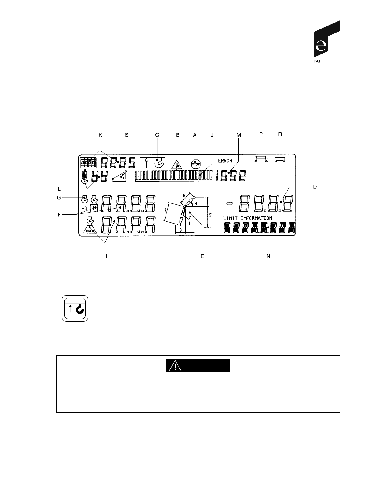
3.3 CONTROL IDENTIFICATION
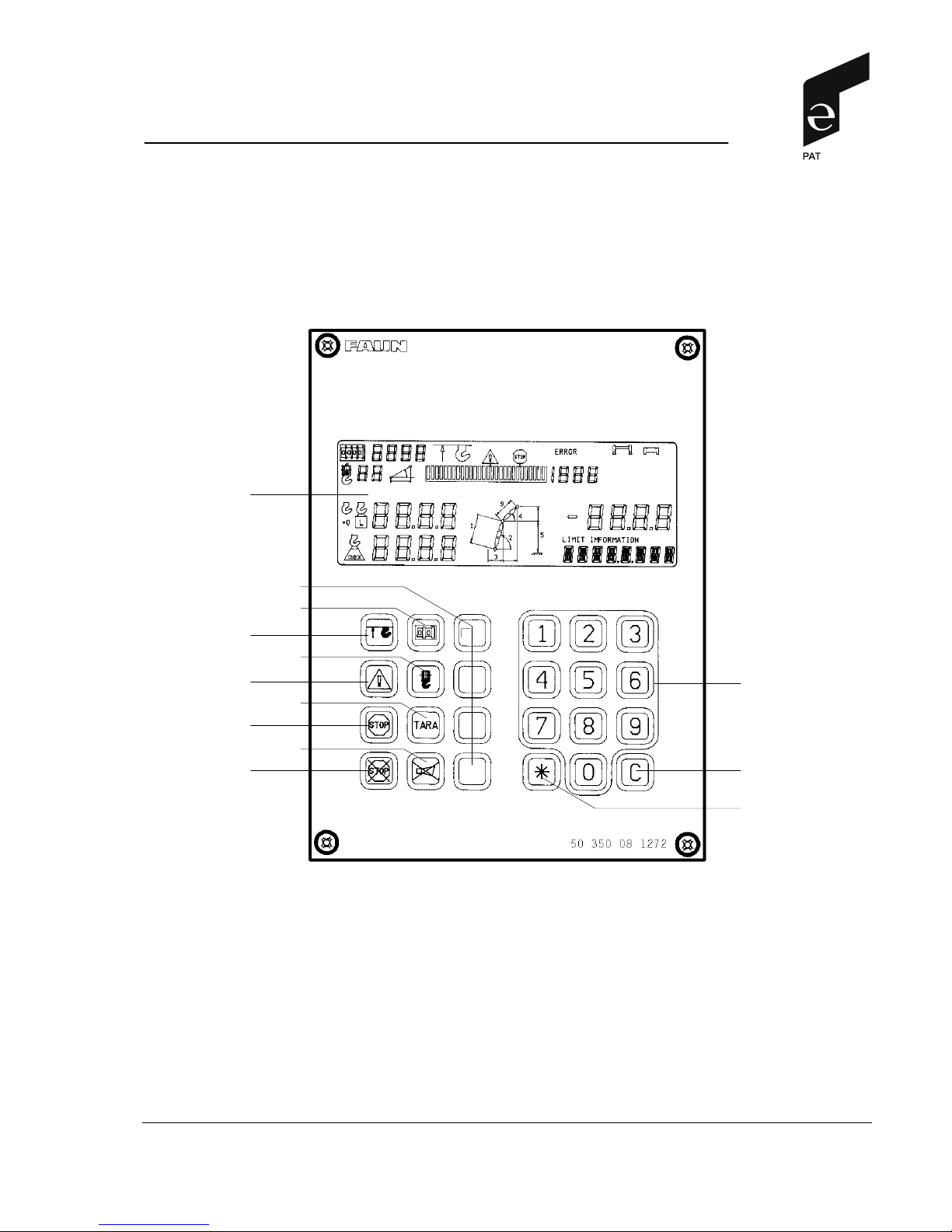
Figure 1 illustrates the controls and displays of the DS 350 safe load indicator. The numbers of the
illustration correspond to the numbers in the following list which describes the function of each control:
1 data display, multi functional
2 A2B switch pilot lamp
3 Prewarning lamp (load moment)
4 Overload lamp (load moment)
5 Pilot lamp "Bridging LMI"
6 Button "operating mode"
7 Button "Reeving"
8 Button "Taring"
9 Button "Alarm off"
(10) without function (evtl. symbol w/o signification)
(11) without function
(12) without function
(13) without function
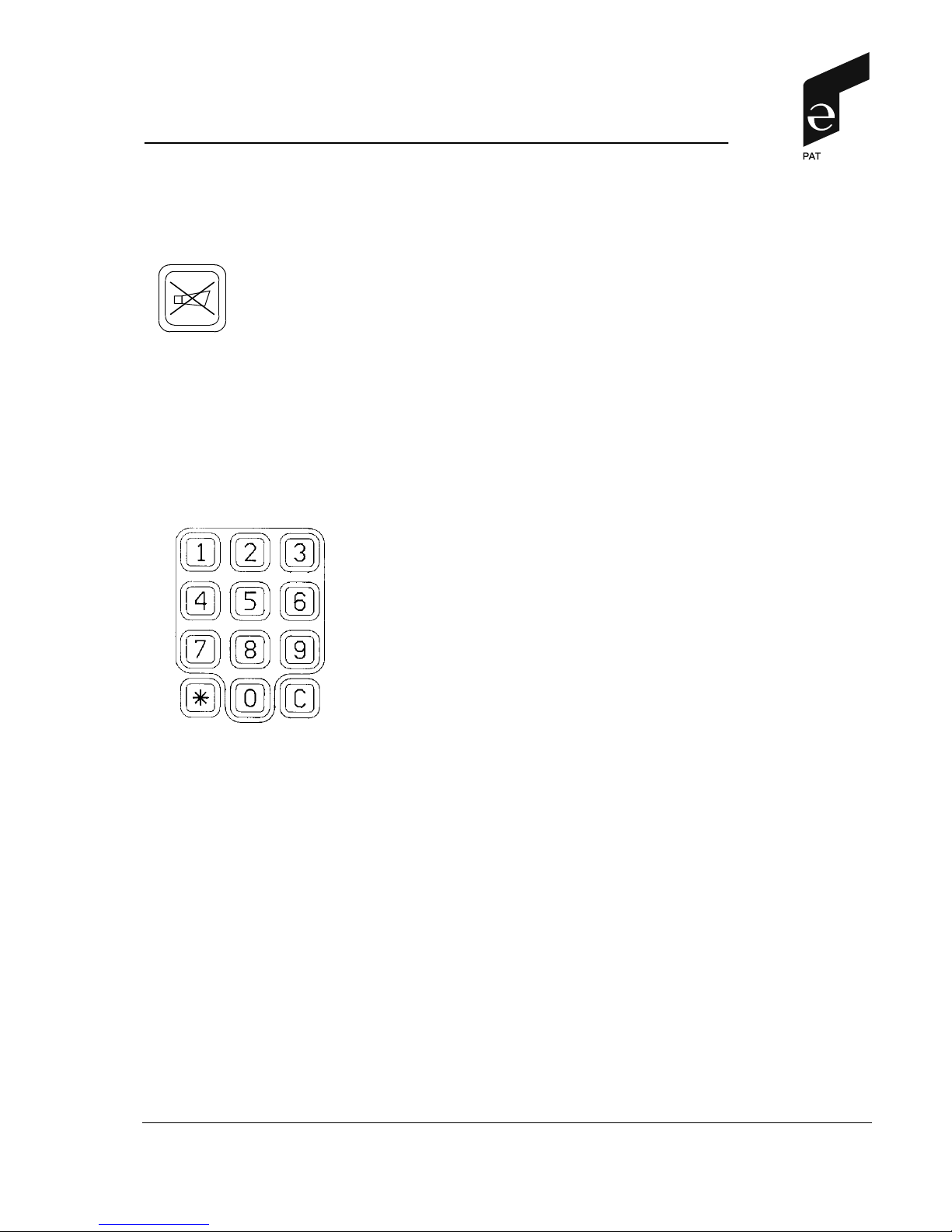
14 Numerical keys 0...9
15 Key "Acknowledgment"
16 Key "Asterix" (evtl. for comma inputs)
14
6
1
2
3
4
5
7
8
9
10...13
15
16
fig. 1
(standard)
Page 8
Control Identification
© 1996-2001 by PAT GmbH ∙ D-76275 Ettlingen ∙ Hertzstr. 32 - 34 ∙ ++49 (0) 7243 709-0 ∙ FAX ++49 (0) 7243 709-141 8
19_1272E.DOC / 2001-04-02 / Rev. C / ko.
(1) DATA DISPLAY
The DATA DISPLAY (1) is a multi-functional LC display which shows load, geometrical and crane
data. The display is further described at chapter 3.4.
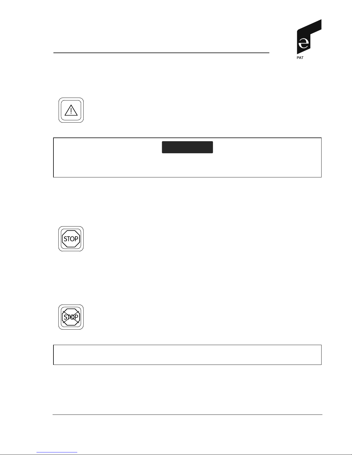
(2) ANTI-TWO BLOCK INDICATOR
The red ANTI-TWO-BLOCK INDICATOR (2) will light up when the
anti-two-block limit switch contacts open, indicating that a twoblocking condition is approaching. At the same time the audible
alarm will sound.
The following crane movements will be stopped subsequently:
hoist up, telescope out, boom down.
WARNING
This condition, if not prevented, will cause the wire rope to break, allowing the load to fall.
Two blocking can be caused by raising the load into the boom head, lowering the boom
without paying out hoist line and, in case of a hydraulic crane, by extending the boom without paying out hoist line.
Page 9
Control Identification
© 1996-2001 by PAT GmbH ∙ D-76275 Ettlingen ∙ Hertzstr. 32 - 34 ∙ ++49 (0) 7243 709-0 ∙ FAX ++49 (0) 7243 709-141 9
19_1272E.DOC / 2001-04-02 / Rev. C / ko.
(3) LOAD MOMENT PREWARNING LIGHT
The yellow LOAD MOMENT PREWARNING LIGHT (3) will light up
when the load on the crane is between 90 and 100 % of the crane
rating, indicating that an overload condition is approaching.
A
TTENTION
This means for the operator to continue his crane operation with extreme caution.
(4) LOAD MOMENT LIMIT LIGHT
The red LOAD MOMENT LIMIT LIGHT (4) warns the operator that
a rated load condition has been reached. It lights up when the load
on the crane reaches the crane load capacity.
The audible alarm also sounds when this condition has been
reached. The following crane movements will be stopped concurrently: hoist up, boom down.
(5) OVERRIDE KEY WARNING LIGHT
This red pilot lamp lights up if the cutoff function of the LMI system
has been manually bridged. The manual bridging is done by a key
switch which is located at the side of the central unit housing.
This key may only be use in emergencies and by authorized personnel exclusively.
In this context, the safety instructions on page 4 of this manual
absolutely have to be followed.
Page 10
Control Identification
© 1996-2001 by PAT GmbH ∙ D-76275 Ettlingen ∙ Hertzstr. 32 - 34 ∙ ++49 (0) 7243 709-0 ∙ FAX ++49 (0) 7243 709-141 10
19_1272E.DOC / 2001-04-02 / Rev. C / ko.
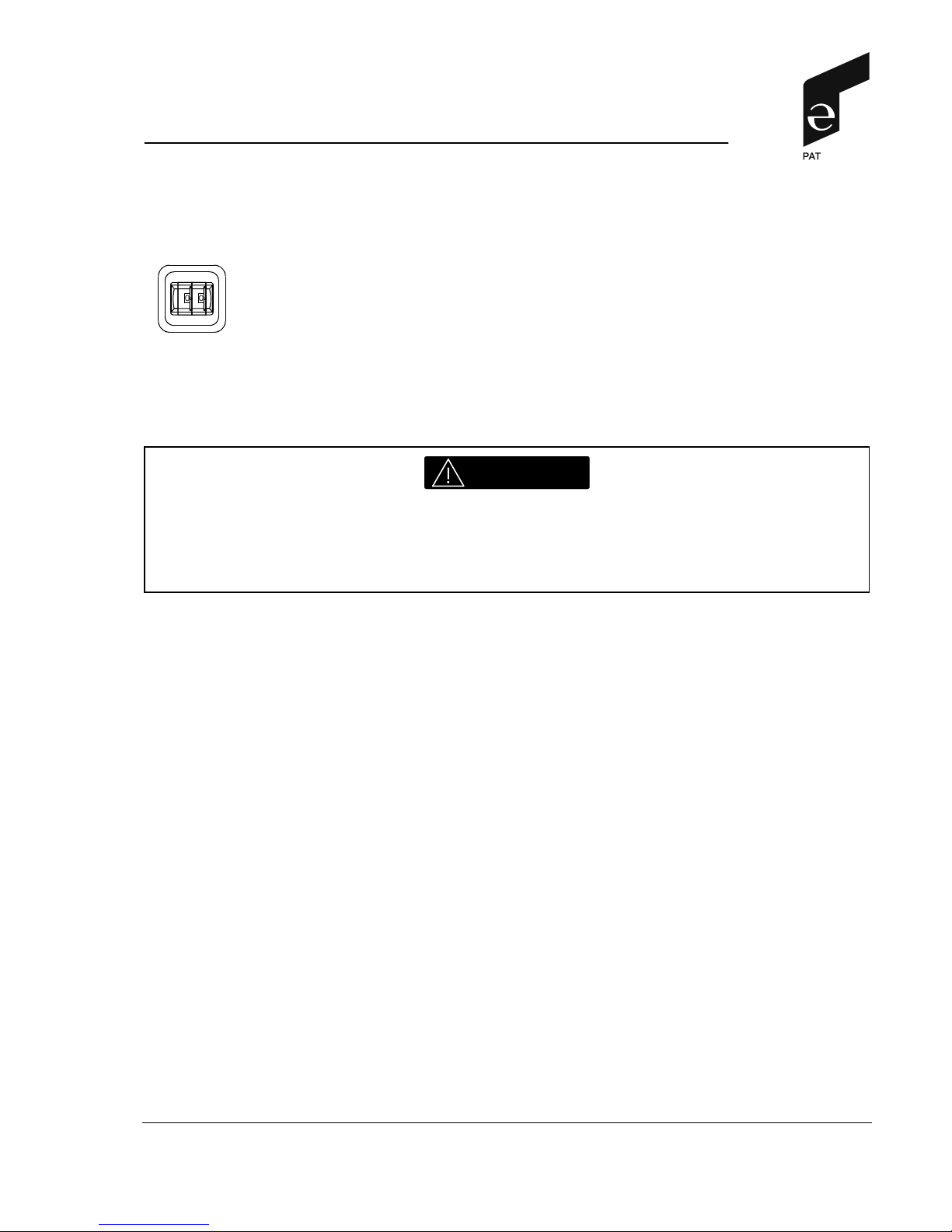
(6) Button "Operating Mode"
The button „Operating mode" (6) is actuated if a new operating
mode code (e.g. upon modification of the operating state) is to be
entered.
The button "Operating mode" lights up upon actuation, thus indicating that the function "Input of an operating mode code" has
been activated. At the same time, the A2B switch pilot lamp (2)
and the overload pilot lamp (4) light up and the crane movements
are interrupted.
WARNING
The correct setting of the Operating Code Switch is of utmost importance for the proper
function of the system and the crane. Therefore, only crane operators who are thoroughly
familiar with crane load capacity charts and the use and operation of the system shall set
the Operating Code Switch.
· The procedure on how to enter an operating mode code is described in chapter 4.1.
Page 11
Control Identification
© 1996-2001 by PAT GmbH ∙ D-76275 Ettlingen ∙ Hertzstr. 32 - 34 ∙ ++49 (0) 7243 709-0 ∙ FAX ++49 (0) 7243 709-141 11
19_1272E.DOC / 2001-04-02 / Rev. C / ko.
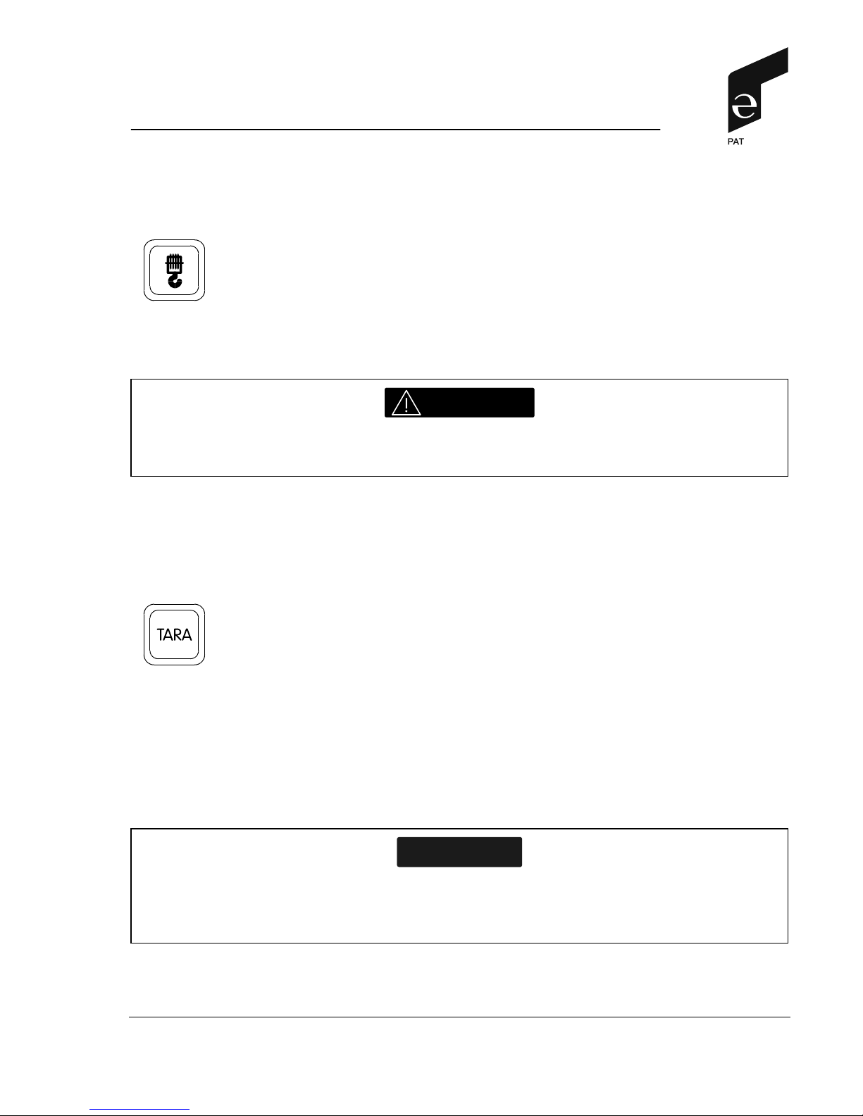
(7) Button "Reeving"
The button Reeving (7) is actuated if a new reeving is to be en-
tered.
The button Reeving lights upon actuation to indicate that the function "Enter the reeving" has been activated.
At the same time, the A2B switch pilot lamp (2) and the overload
pilot lamp (4) light up and the crane movements are interrupted.
WARNING
The correct setting is of utmost importance for the proper function of the system and the
crane.
· The procedure on how to enter the reeving is described in chapter 4.2.
(8) Button "Taring"
The button "TARE" (8) serves to output the net load on the load
display (see #F, chapter 3.4). The net load is the real load minus
tackle and hook block. The button "TARE" has to be actuated before starting the lifting procedure.
Upon actuation of the button "TARE" (8) the load display is set to
zero (tared) and the tare symbol (see #G, chapter 3.4) starts to
blink. When the load is lifted, the load display shows the net load
(payload).
As soon as the working radius (by angle or radius modification) is
modified, the display shows again the real load and the taring
function is completed.
NOTE
The real load contains hook block, lifting rope and all tackle. The net load is the present
load on the hook without tackle. Display errors can be caused by environmental influences
such as wind acting on boom or load.
Page 12
Control Identification
© 1996-2001 by PAT GmbH ∙ D-76275 Ettlingen ∙ Hertzstr. 32 - 34 ∙ ++49 (0) 7243 709-0 ∙ FAX ++49 (0) 7243 709-141 12
19_1272E.DOC / 2001-04-02 / Rev. C / ko.
(9) Button "Buzzer off"
Press this button to temporarily interrupt the audible alarm.
The audible alarm sounds in the following cases:
System test, overload, imminent hoist end situation (if A2B switch
function is registered by the LMI system, malfunction of the LMI as
well as recognized operator's errors.
(10)-(13) without function (evtl. existing symbol without signification)
(14) Numerical keypad
The numerical keys are used for the following inputs:
· Input of the operating mode code (see chapter 4.1)
· Enter the number of reevings (see chapter 4.2)
· Call the geometry data
During the crane operation it is possible to display certain geometry data such as length, angle, etc. on the data display (1) in the
field geometry data D (please refer to chapter 3.4).
Procedure on how to select geometry data:
a) Note the number(s) according to the assignment in the crane symbol (E) of the data display (1) or
the table
b) Enter digit(s) on the numerical keypad (14). Entered digits are shown in the text display (N)
c) Press "C" (15) to confirm the input. The respective arrow in the crane symbol (E) blinks.
Page 13

Control Identification
© 1996-2001 by PAT GmbH ∙ D-76275 Ettlingen ∙ Hertzstr. 32 - 34 ∙ ++49 (0) 7243 709-0 ∙ FAX ++49 (0) 7243 709-141 13
19_1272E.DOC / 2001-04-02 / Rev. C / ko.
Table: Standard version
input: display: unit: / notes:
1
Length of the main boom meter
2
Angle of Boom degrees
3
Operating radius (incl. extension, if any) meter
4
Angle of the jib or extension (if any) degrees
5
Height of the boom tip (above the ground level) meter
6 Test position: All warning lights and characters of the
Data display (1) will be displayed in order to test the proper
function
7 - no function
8 Actual moment used for service only
9
Length of the jib or extension (if any) meter
10 - no function
11 Actuation pressure in bars used for service only
12 Pressure luffing cylinder (piston side) in bar used for service only
13 Pressure luffing cylinder (rod side) in bar used for service only
14
Wind speed (if sensor is connected)
15 Length Tele 1+2 measured used for service only
16 Length Tele 1+2 corrected used for service only
Table: UK version
input: display: unit: / notes
1
Radius (1A) or Angle (1B) of main boom unit depending on program
2
Length of the main boom unit depending on program
3
Height of the boom tip (above the ground level) unit depending on program
4 - no function
5 - no function
6 Test position: All warning lights and characters of the
Data display (1) will be displayed in order to test the proper
function
7
Angle of the jib or extension (if any) degrees
8 Actual moment used for service only
9
Length of the jib or extension (if any) unit depending on program
10 - no function
11 Actuation pressure in bar used for service only
12 Pressure luffing cylinder (piston side) in bar used for service only
13 Pressure luffing cylinder (rod side) in bar used for service only
14
Wind speed (if sensor is connected)
15 Length tele 1+2 measured used for service only
16 Length tele 1+2 corrected used for service only
Page 14

Control Identification
© 1996-2001 by PAT GmbH ∙ D-76275 Ettlingen ∙ Hertzstr. 32 - 34 ∙ ++49 (0) 7243 709-0 ∙ FAX ++49 (0) 7243 709-141 14
19_1272E.DOC / 2001-04-02 / Rev. C / ko.
(15) Button "C"
This button is required to confirmed the following inputs (i.e. the
inputs become valid only after acknowledgment):
· Enter an operating mode code
· Enter a number of reeving
· Select geometry value
(16) Button "asterisk"
This key might be required for the input of decimals.
Page 15

Data Display
© 1996-2001 by PAT GmbH ∙ D-76275 Ettlingen ∙ Hertzstr. 32 - 34 ∙ ++49 (0) 7243 709-0 ∙ FAX ++49 (0) 7243 709-141 15
19_1272E.DOC / 2001-04-02 / Rev. C / ko.
3.4 DATA DISPLAY
A Overload Symbol
This red symbol is permanently lit. It will flash when the load on the
crane is in excess of 100% of the crane rating.
B Prewarning Symbol
This yellow symbol is permanently lit. It will flash when the load on
the crane is between 90% and 100% of the crane rating, indicating
that an overload condition is approaching
C Anti Two-Block Indicator
This symbol will light when the hoist limit switch contacts open,
indicating that a two-blocking condition has occured.
The term "two block" is a crane term which refers to a condition which occurs when the hook block
comes into contact with the boom head. This condition, if not prevented, will cause the wire rope to
break, allowing the load to fall. Two blocking can be caused by raising the load into the boom head,
lowering the boom without paying out hoist line and, in case of a hydraulic crane, by extending the
boom without paying out hoist line.
representation: standard version
Page 16

Data Display
© 1996-2001 by PAT GmbH ∙ D-76275 Ettlingen ∙ Hertzstr. 32 - 34 ∙ ++49 (0) 7243 709-0 ∙ FAX ++49 (0) 7243 709-141 16
19_1272E.DOC / 2001-04-02 / Rev. C / ko.
D Geometrical Data Display
Depending on the digit selected on the numerical keypad (14), this
display shows the corresponding geometrical value.
The digit to be selected corresponds to the assignment in the
crane symbol E. The proceeding on how to select a determined
geometry display is described under #14, in chapter 3.3.
E Crane Symbol
The Crane Symbol (13) indicates the geometry data which can be
selected by numerical keys 0...9. The respective values are then
displayed on the geometry data display D.
F Load Display
This digital display informs the operator about the actual load on
the crane (total load).
After pressing the button "TARE" (8), the net load will be displayed.
G Tare Symbol
This symbol will light after pressing the button "TARE" (8) to have
the net load displayed.
When changing the boom position, the net load indication disappears and the taring will automatically be canceled
NOTE: The total load includes the load of the hook block, the hoist
line and all tackle. The net load is the actual load on the hook
block without tackle. Display errors can be caused by reason of
environmental factors such as wind acting upon the crane and the
load.
H Rated Load Display
This display shows the maximum load for the crane corresponding
to the actual radius and operating mode.
representation: standard version
Page 17

Data Display
© 1996-2001 by PAT GmbH ∙ D-76275 Ettlingen ∙ Hertzstr. 32 - 34 ∙ ++49 (0) 7243 709-0 ∙ FAX ++49 (0) 7243 709-141 17
19_1272E.DOC / 2001-04-02 / Rev. C / ko.
J Load Moment Display
This bar graph display indicates how much of the crane's rated
capacity is being used.
As the rated capacity of the crane changes as it is moved through
its various motions, the utilization display will constantly change as
well.
The bar graph display has three sections:
· a green and safe section (0% to 90% of the rated cap.)
· a yellow prewarning section (90% to 100% of the rated cap)
· a red overload section (beyond 100% of safe working load).
K Operating Mode Display
This display provides the crane operator with information about the
operating mode number the load moment indicator works with.
The operating mode number must coincide with the number valid for the respective load curve
and must be checked.
This display also indicates automatic changes of the operating mode, e.g. with different load curves in
different slewing zones.
The machine configurations are listed in the separate table which is supplied with each load moment
indicator. The operating code is adjusted by means of button "operating mode" (6) (Þ see chapter 4.1
for the proceeding).
L Reeving Display
This display informs about the number of falls (parts of line) used
to reeve the hook block (ref. #7, chapter 3.3).
M Error Code Display
In case of an error, this red display will show a code number which
describes the reason. For decoding that number, refer to chapter
7, list of 'Error Codes'.
Page 18

Data Display
© 1996-2001 by PAT GmbH ∙ D-76275 Ettlingen ∙ Hertzstr. 32 - 34 ∙ ++49 (0) 7243 709-0 ∙ FAX ++49 (0) 7243 709-141 18
19_1272E.DOC / 2001-04-02 / Rev. C / ko.
N Text Display / Tele Percentage Display
Depending on the program version, additional information are displayed in this field, e.g. the identification number for the geometry
data according to crane symbol E.
In versions with tele percentage display, the telescoping lengths
of the telescopes are displayed in the format: Tele 1 \ Tele 2 \ Tele
3 (+4) (in %)
If required, the following information are displayed:
· "SYSTST" during test mode
· "SYSERR" together with "E93" in error code display M
· "CU-ERR" together with "E94" in error code display M
P Symbol "On Outriggers"
This symbol is displayed when outriggers are required in the operating mode adjusted.
R Symbol "On Rubber"
This symbol is displayed when "free, on rubber" is required in the
operating mode adjusted.
S Indicator Radius / Angle Program
Depending on the load chart, the cutoff in case of overload is carried out via the radius or the boom angle. This indicator shows an
angle with arrow in angle-related programmings. At radius related
programming an angle with radius dimensioning is displayed.
Page 19

Programming
© 1996-2001 by PAT GmbH ∙ D-76275 Ettlingen ∙ Hertzstr. 32 - 34 ∙ ++49 (0) 7243 709-0 ∙ FAX ++49 (0) 7243 709-141 19
19_1272E.DOC / 2001-04-02 / Rev. C / ko.
4. PROGRAMMING
Upon switching on the system it is necessary to enter the operating parameters corresponding to the
actual equipment of the crane. Here, the correct inputs by the crane operator is of utmost importance.
This procedure consists of two parts:
· Programming of the LMI to the rigging state of the crane using the correct operating code for the
selected load chart
· Enter the reeving corresponding the actual reeving
4.1 Programming of the Operating Mode
The key operating mode (6) serves to adjust the LMI to the rigging condition of the crane. The required operating code is indicated in the load chart.
WARNING
The correct setting of the Operating Code Switch is of utmost importance for the proper
function of the system and the crane. Therefore, only crane operators who are thoroughly
familiar with crane load capacity charts and the use and operation of the system shall set
the Operating Code Switch.
The operating mode is adjusted as follows:
a) Please refer to the operating mode for the code number and to the load chart for the "operating
code".
This number is indicated in the load chart, such as "on outriggers", "on rubber", "with jib", etc..
b) Note the code number corresponding to the crane configuration.
c) Start programming by pressing button (6) "operating mode". The key lights up.
During the programming, the system temporarily interrupts the crane movements. Furthermore, pilot
lamps (2) and (4) light up.
d) Enter the code number on the numerical keypad (14). The code number is shown on data dis-
play K.
e) Confirm the input by pressing „C“ (15), or enter again the number.
The entered operating mode code is confirmed by pressing key „C“. The input becomes valid upon acknowledgment. Upon acknowledgment, the key is normally lit again.
Page 20

Programming
© 1996-2001 by PAT GmbH ∙ D-76275 Ettlingen ∙ Hertzstr. 32 - 34 ∙ ++49 (0) 7243 709-0 ∙ FAX ++49 (0) 7243 709-141 20
19_1272E.DOC / 2001-04-02 / Rev. C / ko.
· Invalid operating modes are displayed by means of "EEEE".
The system is now ready for operation. The cutoff of the crane movements is canceled and pilot
lamps and audible alarms are turned off.
The data display (1) now shows the present data.
WARNING
Failure to properly program the LMI with the correct operating code may result in property
damage or serious bodily injury or death to personnel.
To assure the crane is properly programmed, verify that the operating code and the load
capacity chart match the lifting configuration of the crane.
4.2 Adjustment of the Reeving
The button "Reeving" (7) serves for the input of the present reeving of hook block. The number of
reeving is entered on the numerical keypad (14) by selecting the respective number. The reeving is
displayed on the data display (1) (see also #L; chapter 3.4).
The reeving is adjusted as follows:
a) Start the adjustment procedure by pressing the button "Reeving" (7).The key lights up.
b) Enter the reeving in the numerical keypad (14)
Now, the entered reeving is shown on the reeving display.
c) Acknowledge the input by pressing key „C“ (15)
Upon actuation of key „C“ (15) the entered reeving is acknowledged, i.e. the input is only valid after the
acknowledgment. The button Reeving (7) is normally lit again.
WARNING
The correct setting is of utmost importance for the proper function of the system and the
crane.
Page 21

Pre-Operation Inspection and Calibration Verification
© 1996-2001 by PAT GmbH ∙ D-76275 Ettlingen ∙ Hertzstr. 32 - 34 ∙ ++49 (0) 7243 709-0 ∙ FAX ++49 (0) 7243 709-141 21
19_1272E.DOC / 2001-04-02 / Rev. C / ko.
5. PRE-OPERATION INSPECTION and Calibration Verification
Prior to operating the crane, the following electrical connections must be checked to ensure that the
system is properly connected for the crane configuration.
Machines with only a Main Hoist
If the crane works only with the boom and without boom extension, no additional connections are
necessary. However, be sure the weight of the anti two-block switch is properly installed on the main
hoist load line. With even parts of hoisting line, the weight shall be attached to the dead-end line. With
odd parts of hoisting line, the weight shall be attached to the line of lowest speed.
If the crane works with boom extension, the connecting cable shall be installed between the junction
box on the boom extension and the boom junction box. The weight attached to the main hoist anti
two-block switch shall be removed. In that case the anti two-block switch has to be locked with the red
Anti Two-Block Retainer, which is fixed with a red lanyard at the anti two-block switch (described on
page 16). Then the weight shall be reattached to the boom extension anti two-block switch.
WARNING
Failure to re-position the anti two-block switch weight will prevent the overhoist system
from functioning properly. No weight shall be on the main hoist anti two-block switch when
the boom extension is being used.
Machines with Main and Auxiliary Hoists
If the boom extension is not in the operating position, the by-pass plug shall be installed in the main
boom junction box. The weight of the main hoist anti two-block switch shall be installed.
If the boom extension is in the operating position, the connecting cable shall be installed between the
junction boxes on the boom extension and the main boom. Weights shall also be attached to the anti
two-block switches on both the main boom and boom extension.
If the boom extension is in the operating position and no load line is being used on main boom, to
prevent injury or damage to equipment, the weight shall be removed from main boom switch. In that
case the anti two-block switch has to be locked with the red Anti Two-Block Retainer, which is fixed
with a red lanyard (not shown) at the anti two-block switch.
Page 22

Pre-Operation Inspection and Calibration Verification
© 1996-2001 by PAT GmbH ∙ D-76275 Ettlingen ∙ Hertzstr. 32 - 34 ∙ ++49 (0) 7243 709-0 ∙ FAX ++49 (0) 7243 709-141 22
19_1272E.DOC / 2001-04-02 / Rev. C / ko.
After the electrical connections have been checked to insure that the system is properly connected for
the crane configuration, the following checks shall be made:
1. Check the electrical wiring connecting the various parts of the system for physical damage.
2. Check the anti two-block switches and weights for free movement.
3. Check the spring-loaded cable reel to be sure it is free to rotate, has tension and the cable is
reeled properly.
WARNING
The following tests shall be performed with care to prevent damage to the machine or injury
to personnel. Proper functioning of the system requires successful completion of these
tests before operating the machine.
If the operator cannot see the load handling device approaching the boom nose, he shall have an
assistant (signal person) watch the load handling device. The operator shall be prepared to stop the
machine immediately should the LMI system not function properly as indicated by lighting the red
warning light, sounding the audible alarm and locking the crane movements, hoist up, (telescope out)
and boom down.
Check the anti two-block alarm light and the audible alarm by performing one of the following tests:
1. By manually lifting the weight attached to the anti two-block switches. When the weight is lifted, the
audible alarm should sound, the anti two-block alarm light should light.
2. Slowly raise the main boom load handling device to create a potential two-block condition. When
the load handling device lifts the weight, the audible alarm should sound, the anti two- block alarm
light (2) should light and the motion of the load handling device should be stopped. Lower the load
handling device slightly to eliminate this condition.
3. Slowly lower the boom to create a potential two-block condition. When the load handling device
lifts the weight, the audible alarm should sound, the anti two-block alarm light should light and the
boom lowering function should be stopped. Lower the load handling device slightly to eliminate this
condition.
4. Slowly extend (telescope) the boom to create a potential two-block condition. When the load handling device lifts the weight, the audible alarm should sound, the anti two-block alarm light should
light and the boom telescope out function should be stopped. Lower the load handling device
slightly to eliminate this condition.
Page 23

Pre-Operation Inspection and Calibration Verification
© 1996-2001 by PAT GmbH ∙ D-76275 Ettlingen ∙ Hertzstr. 32 - 34 ∙ ++49 (0) 7243 709-0 ∙ FAX ++49 (0) 7243 709-141 23
19_1272E.DOC / 2001-04-02 / Rev. C / ko.
WARNING
If the light and audible alarm do not function as described and the crane movements are not
stopped, the system is not working properly. The malfunction shall be corrected before operating the crane.
5. If the crane is equipped with a boom extension, repeat the test procedure for the boom extension
anti two-block switch.
6. Check that the display of the main boom length agrees with the actual boom length.
7. Check that the display of the main boom angle agrees with the actual boom angles.
8. Check that the display of the operating radius of the crane agrees with the actual radius.
9. Check the load display by lifting a load of known weight.
5.1 OPERATION
After being properly checked, the LMI is operational. The operator shall be thoroughly familiar with all
controls of the LMI and he shall properly set the Reeving Switch (external unit) before operating the
crane. The proper function of the system shall be checked by lifting a load of known weight and comparing the load to the information displayed on the LMI.
Rated loads include the weight of the hook block, slings, and auxiliary load handling devices. Their
combined weights shall be subtracted from the listed load capacities as stated on the load capacity
chart to obtain the net load to be lifted.
WARNING
If any of the displays reflect a deviation between displayed and actual values an authorized
PAT service representative shall be called for repair of the system or re-verification of the
crane's LMI calibration.
WARNING
Any structural modifications or changes to the crane shall require re-verification of the
crane's LMI calibration.
Page 24

Pre-Operation Inspection and Calibration Verification
© 1996-2001 by PAT GmbH ∙ D-76275 Ettlingen ∙ Hertzstr. 32 - 34 ∙ ++49 (0) 7243 709-0 ∙ FAX ++49 (0) 7243 709-141 24
19_1272E.DOC / 2001-04-02 / Rev. C / ko.
6. SERVICE AND MAINTENANCE
Daily maintenance of the load moment indicator consists of inspecting:
1. The electrical wiring connecting the various parts of the system. If electrical wiring is damaged,
it shall be replaced immediately.
2. If the insulation is worn on the length sensor cable or cable guides are damaged, these parts
shall be replaced. (telescope cranes only)
3. Check the anti two-block limit switches for freedom of movement.
4. The cable reel shall be under tension to operate properly. (telescope cranes only)
5. Check the pressure transducers at the lift cylinder(s) and the connecting hoses for oil leakage.
6. Check mechanical installation, electrical connection and function of boom extension configura-
tion sensors. (if installed)
7. Check mechanical installation, electrical connection and function of boom nose configuration
sensor. (if installed)
8. Check mechanical installation, electrical connection and function of hoist line sensor. (if in-
stalled)
9. Check mechanical installation, electrical connection and function of crawler configuration sen-
sors. (if installed)
10. Check mechanical installation, electrical connection and function of inclination sensor. (if any)
NOTE
Other than correcting the problems identified in the Malfunctions Table and replacing faulty
mechanical parts and cables, no other repairs shall be performed by non expert personnel.
Page 25

Troubleshooting
© 1996-2001 by PAT GmbH ∙ D-76275 Ettlingen ∙ Hertzstr. 32 - 34 ∙ ++49 (0) 7243 709-0 ∙ FAX ++49 (0) 7243 709-141 25
19_1272E.DOC / 2001-04-02 / Rev. C / ko.
7. TROUBLESHOOTING
7.1 General
In case of a malfunction of the system, the data display M will indicate a code "E xx" which identifies
the system malfunction.
The error codes listed in the Malfunction Table will identify various faults which can occur with the
LMI. Following the Malfunction Table are pages which explain each fault and describe the action
which shall be taken to correct the fault.
Faults within the electronic microprocessor shall only be repaired by factory trained service personnel.
When these faults occur, the competent service organization shall be contacted.
7.2 System Messages
Code Letter O: Overload
P: Prewarning
H: Anti-two Block Switch activated
Page 26

Troubleshooting
© 1996-2001 by PAT GmbH ∙ D-76275 Ettlingen ∙ Hertzstr. 32 - 34 ∙ ++49 (0) 7243 709-0 ∙ FAX ++49 (0) 7243 709-141 26
19_1272E.DOC / 2001-04-02 / Rev. C / ko.
7.3 ERROR CODE TABLE
Error Code E01
Error: Fallen below radius range or angle range exceeded
Cause: Fallen below the minimum radius or gone past the maximum angle specified in the respective load
chart due to luffing in the boom too far.
Remedy: Luff out the boom to a radius or angle specified in the load chart.
Error Code E02
Error: Radius range exceeded or fallen below angle range
Cause: Gone past the maximum radius or fallen below the minimum angle specified in the respective load
chart due to luffing out the boom too far.
Remedy: Luff in the boom to a radius or angle specified in the load chart.
Error Code E04
Error: Operating mode not available
Cause: Incorrect setting of operating mode switch in the console
Remedy: Set operating mode switch correctly observing the assignment to the crane configuration.
Error Code E05
Error: Prohibited length range
Cause: a. Boom has been extended either too far or not far enough, e.g. if it is prohibited to go beyond a
certain maximum boom length or with load curves for jibs where the main boom has to be ex-
tended to a certain length.
b. Length sensor adjustment has changed, e.g. the cable slid off the length sensor reel.
c. Clutch between length sensor pot and drive is defective.
d. Failure of +5 V supply for analog part of SLI main board.
e. Cable between central unit and length sensor is either defective or disconnected.
f. Defective length potentiometer.
Remedy: a. Extend/retract boom to correct length.
b. Retract boom. Check the prestress of the cable reel (cable must be taut). Open the length sensor
and carefully turn the length sensor pot counterclockwise until the detent by use of a screwdriver.
c. Replace the complete clutch including drive wheel and adjust length sensor pot as described in b.
d. Check +5 V supply. Exchange main board in case of voltage failure or breakdown when loaded
with 50 ohm approx.
e. Check cable and plugs, exchange, if necessary.
f. Replace length potentiometer.
Page 27

Troubleshooting
© 1996-2001 by PAT GmbH ∙ D-76275 Ettlingen ∙ Hertzstr. 32 - 34 ∙ ++49 (0) 7243 709-0 ∙ FAX ++49 (0) 7243 709-141 27
19_1272E.DOC / 2001-04-02 / Rev. C / ko.
Error Code E07
Error: No acknowledgement from overload relay
Cause: Overload relay is caught, defective or not being driven.
Remedy: Exchange relay. If this is not satisfactory, replace terminal board.
Error Code E08
Error: No acknowledgement from anti-two block switch relay
Cause: Anti-two block switch relay is caught, defective or not being driven.
Remedy: Exchange relay. If this is not satisfactory, replace terminal board.
Error Code E11
Error: Fallen below the lower limit value for measuring channel "Length of Telescopic Boom"
Cause: a. Cable between central unit and length sensor is defective or disconnected. Water inside the con
nector of length/angle sensor.
b. Length potentiometer is defective.
c. Electronic component in the measuring channel is defective.
Remedy: a. Check cable as well as connector, exchange, if need be.
b. Exchange length potentiometer.
c. Exchange main board.
Error Code E12
Error: Fallen below the lower limit value in the measuring channel "Pressure Piston-Side"
Cause: a. Cable between central unit and pressure transducers defective or water inside the connectors.
b. Pressure transducer defective.
c. Electronic component in the measuring channel is defective.
Remedy: a. Check cables and connectors, exchange, if need be.
b. Exchange pressure transducer.
c. Exchange main board.
Error Code E13
Error: Fallen below the lower limit value in the measuring channel "Pressure Rod-Side"
Cause: a. Cable between central unit and pressure transducers defective or water inside the connectors.
b. Pressure transducer defective.
c. Electronic component in the measuring channel is defective.
Remedy: a. Check cables and connectors, exchange, if need be.
b. Exchange pressure transducer.
c. Exchange main board.
Error Code E14
Error: Fallen below the lower limit value in the measuring channel "actuating pressure".
Page 28

Troubleshooting
© 1996-2001 by PAT GmbH ∙ D-76275 Ettlingen ∙ Hertzstr. 32 - 34 ∙ ++49 (0) 7243 709-0 ∙ FAX ++49 (0) 7243 709-141 28
19_1272E.DOC / 2001-04-02 / Rev. C / ko.
Cause: a. Cable between central unit and pressure transducer defective or water inside the connector.
b. Pressure transducer is defective.
c. Electronic component in the measuring channel is defective.
Remedy: a. Check cable and connectors, exchange, if need be.
b. Exchange pressure transducer.
c. Exchange main board.
Error Code E16
Error: Fallen below lower limit value for measuring channel "wind speed"
Cause: a. Cable between central unit and anemometer defective or disconnected or water inside the con-
nector.
b. Anemometer is defective.
c. Electronic component in the measuring channel is defective.
Remedy: a. Check cable and connectors, exchange, if need be.
b. Exchange anemometer.
c. Exchange main board.
Error Code E17
Error: Fallen below lower limit value for measuring channel "length tele I(+II)"
Cause: a. Cable between central unit and length sensor defective or disconnected or water inside the con-
nector.
b. Length sensor is defective.
c. Electronic component in the measuring channel is defective.
Remedy: a. Check cable and connectors, exchange, if need be.
b. Exchange Length sensor.
c. Exchange main board.
Error Code E19
Error: Reference voltage is defective
Cause: a. The total of the supply and reference voltages at MP10 is less than 3.1 V.
b. A/D converter is defective.
Remedy: a. Check supply voltages.
b. Exchange main board.
Page 29

Troubleshooting
© 1996-2001 by PAT GmbH ∙ D-76275 Ettlingen ∙ Hertzstr. 32 - 34 ∙ ++49 (0) 7243 709-0 ∙ FAX ++49 (0) 7243 709-141 29
19_1272E.DOC / 2001-04-02 / Rev. C / ko.
Error Code E21
Error: Upper limit value for measuring channel "Telescopic Boom Length" exceeded
Cause: a. Cable between central unit and length sensor is defective or disconnected. Water inside the con-
nector of length/angle sensor.
b. Length potentiometer is defective.
c. Electronic component in the measuring channel is defective.
Remedy: a. Check cable as well as connector, exchange, if need be.
b. Exchange length potentiometer.
c. Exchange main board.
Error Code E22
Error: Upper limit value for measuring channel "Pressure Piston-Side" exceeded
Cause: a. Cable between central unit and pressure transducers defective or water inside the connectors.
b. Pressure transducer defective.
c. Electronic component in the measuring channel is defective.
Remedy: a. Check cables and connectors, exchange, if need be.
b. Exchange pressure transducer.
c. Exchange main board.
Error Code E23
Error: Upper limit value in measuring channel "Pressure Rod-Side" exceeded
Cause: a. Cable between central unit and pressure transducers defective or water inside the connectors.
b. Pressure transducer defective.
c. Electronic component in the measuring channel is defective.
Remedy: a. Check cables and connectors, exchange, if need be.
b. Exchange pressure transducer.
c. Exchange main board.
Error Code E24
Error: Upper limit value in measuring channel "actuating pressure" exceeded
Cause: a. Cable between central unit and pressure transducer defective or water inside the connector.
b. Pressure transducer is defective.
c. Electronic component in the measuring channel is defective.
Remedy: a. Check cable and connectors, exchange, if need be.
b. Exchange pressure transducer.
c. Exchange main board.
Page 30

Troubleshooting
© 1996-2001 by PAT GmbH ∙ D-76275 Ettlingen ∙ Hertzstr. 32 - 34 ∙ ++49 (0) 7243 709-0 ∙ FAX ++49 (0) 7243 709-141 30
19_1272E.DOC / 2001-04-02 / Rev. C / ko.
Error Code E25
Error: Upper limit value for measuring channel "Main Boom Angle" exceeded
Cause: a. Cable between central unit and length/angle sensor defective or disconnected or water inside the
connector.
b. Angle sensor is defective.
c. Electronic component in the measuring channel is defective.
Remedy: a. Check cable and connectors, exchange, if need be.
b. Exchange angle sensor.
c. Exchange main board.
Error Code E26
Error: Upper limit value for measuring channel "wind speed" exceeded
Cause: a. Cable between central unit and anemometer defective or disconnected or wat er inside the con-
nector.
b. Anemometer is defective.
c. Electronic component in the measuring channel is defective.
Remedy: a. Check cable and connectors, exchange, if need be.
b. Exchange anemometer.
c. Exchange main board.
Error Code E27
Error: Upper limit value for measuring channel "Length tele I(+II)" exceeded
Cause: a. Cable between central unit and length sensor defective or disconnected or wa ter inside the con-
nector of length/angle sensor.
b. Length potentiometer is defective.
c. Electronic component in the measuring channel is defective.
Remedy: a. Check cable and connectors, exchange, if need be.
b. Exchange length potentiometer.
c. Exchange main board.
Error Code E29
Error: Reference voltage is defective
Cause: a. The total of the supply and reference voltages at MP10 is more than 3.8 V.
b. A/D converter is defective.
Remedy: a. Check the supply voltages.
b. Exchange main board.
Page 31

Troubleshooting
© 1996-2001 by PAT GmbH ∙ D-76275 Ettlingen ∙ Hertzstr. 32 - 34 ∙ ++49 (0) 7243 709-0 ∙ FAX ++49 (0) 7243 709-141 31
19_1272E.DOC / 2001-04-02 / Rev. C / ko.
Error Code E31
Error: Error in the system program
Remedy: Exchange the system program PROM (No. 0).
Error Code E38
Error: Wrong system program in SLI
Cause: The system program in the SLI does not match the programmings in the data EPROM.
Remedy: Exchange the system program PROM (No. 1).
Error Code E39
Error: Wrong system program in SLI
Cause: The system program in the SLI does not match the programmings in the TLK EPROM.
Remedy: Exchange the system program PROM or the TLK EPROM (No. 2).
Error Code E41
Error: Error in the internal write/read memory (RAM) of the computer module 80C537
Remedy: a. Exchange computer module 80C537.
b. Exchange SLI main board with CPU modul.
Error Code E42
Error: Error in the external write/read memory (RAM), part 1
Remedy: a. Exchange write/read memory (CMOS-RAM).
b. Exchange SLI main board.
Error Code E43
Error: Error in the external write/read memory (RAM), part 2
Remedy: a. Exchange write/read memory (CMOS-RAM).
b. Exchange SLI main board.
Error Code E45
Error: Redundancy error in the A/D conversion
Cause: The A/D converter on the processor board and the redundant A/D converter in the CPU 80C537 pro-
vide differing results.
Remedy: Exchange processor board
Error Code E46
Page 32

Troubleshooting
© 1996-2001 by PAT GmbH ∙ D-76275 Ettlingen ∙ Hertzstr. 32 - 34 ∙ ++49 (0) 7243 709-0 ∙ FAX ++49 (0) 7243 709-141 32
19_1272E.DOC / 2001-04-02 / Rev. C / ko.
Error: Error in the A/D converter uPD 7004 on the processor board
Cause: The A/D converter uPD 7004 does not provide a repeater signal
Remedy: Exchange processor board
Error Code E47
Error: a. Malfunction in the monitored write-read memory.
b. The CRC check of the monitored write-read memory provides an inconsistent result.
Cause: a. The CRC character of the monitored write-read memory is incorrect.
b. The buffer battery is discharged (<2V at 1kOhm).
Remedy: a. Restart RCI.
b. Exchange buffer battery on RCI main board.
Error Code E48
Error: Cyclic RAM test: error in the internal write-read memory (RAM) of the controller 80C537
Cause: a. Controller 80C537 defective
b. CPU module defective
c. Processor board defective
Remedy: a. Exchange controller 80C537
b. Exchange CPU module
c. Exchange processor board with CPU module
Error Code E51
Error: Error in the data EPROM or EEPROM
Cause: a. Data EEPROM has no valid data.
b. Jumpers on memory module incorrectly set.
c. Data EPROM defective.
Remedy: a. Load valid data into data EEPROM.
b. Set jumpers in compliance with memory type.
c. Exchange data EPROM.
Error Code E52
Error: Error in load chart EPROM.
Cause: a. Jumpers on memory module incorrect.
b. Load chart EPROM defective.
Remedy: a. Set jumpers According to memory type.
b. Exchange load chart EPROM.
Error Code E56
Error: Error in data EEPROM
Page 33

Troubleshooting
© 1996-2001 by PAT GmbH ∙ D-76275 Ettlingen ∙ Hertzstr. 32 - 34 ∙ ++49 (0) 7243 709-0 ∙ FAX ++49 (0) 7243 709-141 33
19_1272E.DOC / 2001-04-02 / Rev. C / ko.
Cause: a. Jumpers on memory module incorrect.
b. Data EEPROM defective.
Remedy: a. Set jumpers according to memory type.
b. Exchange data EEPROM.
Error Code E57
Error: Error in the serial data EEPROM
Cause: a. Serial data EEPROM has no valid data.
b. Memory module defective.
Remedy: a. Write data into serial EEPROM (with test program or ONLINE function), then restart RCI.
b. Exchange memory module.
Error Code E58
Error: Error in the serial analogue data EEPROM.
Cause: a. Serial analogue data EEPROM has no valid data
b. RCI main board defective
Remedy: a. Write data into serial analogue data EEPROM with test program, then restart RCI
b. Exchange RCI main board.
Error Code E71
Error: Faulty acknowledgement of K1 relay on the terminal board. Relay should have been energized but the
2nd contact is signalled to be off, or the 2nd contact is signalled to be on whereas the relay should
have been de-energized.
Cause: a. K1 relay on terminal board defective
b. main board defective
Remedy: a. Exchange terminal board
b. Exchange main board
Error Codes E72 - E77
Error: Same as E71 but referred to the 2rd thru 7th relay on terminal board
Cause: see E71
Remedy: see E71
Page 34

Troubleshooting
© 1996-2001 by PAT GmbH ∙ D-76275 Ettlingen ∙ Hertzstr. 32 - 34 ∙ ++49 (0) 7243 709-0 ∙ FAX ++49 (0) 7243 709-141 34
19_1272E.DOC / 2001-04-02 / Rev. C / ko.
Error Code E82
Error: Locking error , first telescope
Cause: a. First telescope not locked although second telescope not retracted.
b. Sensors "telescope retracted" or "telescope locked" defective.
Remedy: a. Lock telescope 1.
b. Check sensors.
Error Code E84
Error: Incorrect rigging condition.
Cause: Selected rigging condition not programmed in data EPROM.
Remedy: a. Select different rigging condition.
b. Check program in data EPROM.
Error Code E85
Error: Error in radius calculation
Cause: Calculated radius is too small (negative deflection).
Remedy: Check program in data EPROM.
Error Code E86
Error: Incorrect percentage for at least one telescope
Cause: a. Telescope has a percentage of <-2% or >+106%.
b. Length measurement Tele I (+ II) defective.
c. Measurement of total length incorrect.
Remedy: a. Read individual percentage values on console display. Retract telescope extended too far.
b. Check length measurement Tele I (refer tom E 17)
c. Check length measurement completely (refer to E 11)
Error Code E87
Error: Error in the length measurement.
Cause: a. Malfunction in monitored write-read memory
b. Length measurement Tele I incorrect.
c. Measurement of total length incorrect.
d. Sensors "Tele retracted" or "Tele locked" defective.
Remedy: a. Retract all telescopes and lock Tele I, if applicable.
b. Check length measurement Tele I (+II) - (refer to E 17)
c. Check length measurement completely (refer to E 11)
d. Check sensors.
Error Code E91
Error: No data transmission from console to central unit
Page 35

Troubleshooting
© 1996-2001 by PAT GmbH ∙ D-76275 Ettlingen ∙ Hertzstr. 32 - 34 ∙ ++49 (0) 7243 709-0 ∙ FAX ++49 (0) 7243 709-141 35
19_1272E.DOC / 2001-04-02 / Rev. C / ko.
Cause: a. Interruption of 24 V supply of console.
b. Interruption or accidental ground in the line between console electronics and central unit.
c. Transmitter/receiver module is defective.
Remedy: a. Check for 24 V at terminal X1 of console electronics.
b. Check the connection between console electronics and central unit. If an accidental ground is de-
tected, the transmitter module in the console electronics might be damaged, therefore exchange the
console electronics.
c. Exchange console electronics or SLI main board resp.
Error Code E92
Error: Error in the data transmission from console to central unit
Cause: a. Loose connection in the line between console electronics and central unit.
b. Transmitter/receiver module is defective.
Remedy: a. Check the connection between console electronics and central unit.
b. Exchange console electronics or SLI main board resp.
Error Code E93
Error: Error in the data transmission from central unit to console
Cause: a. Loose connection in the line between central unit and console.
b. Transmitter/receiver module is defective.
Remedy: a. Check the line to the console.
b. Exchange console electronics or SLI main board resp.
Error Code E94
Error: No data transmission from central unit to console
Cause: a .Interruption or accidental ground in the line between central unit and console.
b. 5 V supply of the computer in the central unit is missing.
c. 5 V supply voltage is too low.
d. Transmitter/receiver module is defective.
e. Data PROM is defective.
f. Computer module is defective.
g. Electromagnetic interferences (e.g. when switching contactors or valves).
Remedy: a. Check the line to the console (in case of accidental ground, also exchange console electronics).
b. Check the connection to the power supply.
c. Exchange the power supply module.
d. Exchange the console electronics or SLI main board resp.
e. Check data PROM.
f. Exchange SLI main board.
g. Eliminate the source of interference by inverse diodes or varistors.
Page 36

Troubleshooting
© 1996-2001 by PAT GmbH ∙ D-76275 Ettlingen ∙ Hertzstr. 32 - 34 ∙ ++49 (0) 7243 709-0 ∙ FAX ++49 (0) 7243 709-141 36
19_1272E.DOC / 2001-04-02 / Rev. C / ko.
Error Code E95
Error: No data transmission from console to central unit
Cause: a. Interruption of 24 V supply of console.
b. Interruption or accidental ground in the line between console electronics and central unit.
c. Transmitter/receiver module is defective.
Remedy: a. Check for 24 V at terminal X1 of console electronics.
b. Check the connection between console electronics and central unit. If an accidental ground is de-
tected, the transmitter module in the console electronics might be damaged, therefore exchange the
console electronics.
c. Exchange console electronics or SLI main board resp.
Error Code E96
Error: Error in the internal RAM of CPU 8031.
Cause: a. CPU 8031 in console defective.
b. Console main board defective.
Remedy: a. Exchange CPU 8031 in console.
b. Exchange console main board.
Page 37

Important Notes
© 1996-2001 by PAT GmbH ∙ D-76275 Ettlingen ∙ Hertzstr. 32 - 34 ∙ ++49 (0) 7243 709-0 ∙ FAX ++49 (0) 7243 709-141 37
19_1272E.DOC / 2001-04-02 / Rev. C / ko.
PAMPHLET 1 Cut-off Values for Boom Cranes with Variable Capacity depending
on Variable Radius
The crane cut-off values are calculated by us on the basis of the load charts and construction drawings supplies
by the crane manufacturers.
These theoretical cut-off values must be checked by testing the crane with weighed test loads in all operating
modes and at least in the following equipment conditions depending on the crane type.
· Cranes with fixed boom length during operation:
Minimum, medium and maximum radius with shortest, medium and longest boom length as well as with
shortest, medium and longest jib length with these boom lengths.
· Cranes with variable boom length during operation:
Minimum, medium and maximum radius at each length step as well as with all jibs.
PAMPHLET 2 Important notes for crane operators
The LMI is an operational aid which warns a crane operator of approaching overload conditions and also warns
of overhoist conditions which could cause damage to equipment and personnel.
The device is not, and shall not, be a substitute for good operator judgment, experience and use of accepted
safe crane operating procedures. The responsibility for the safe operation of the crane shall remain with the
crane operator who shall ensure that all warnings and instructions supplied are fully understood and observed.
Prior to operating the crane, the operator must carefully and thoroughly read and understand the information in
the crane/SLI manual to ensure that he knows the operation and limitations of the indicator and crane.
Proper functioning is dependent upon proper daily inspection and observations of the operating instructions set
forth in the manual.
WARNING
This system can be equipped with an override key on the central micro-processor unit. This
key switch bypasses cut-off functions of the load moment indicator device. The switch may
only be used by authorized personnel during emergency situations. Failure to follow this
instruction may result in property damage and/or personal injury.
Page 38

Important Notes
© 1996-2001 by PAT GmbH ∙ D-76275 Ettlingen ∙ Hertzstr. 32 - 34 ∙ ++49 (0) 7243 709-0 ∙ FAX ++49 (0) 7243 709-141 38
19_1272E.DOC / 2001-04-02 / Rev. C / ko.
PAMPHLET 3 Important notes for crane users
In the Federal Republic of Germany, the directives of the Union of German Engineers VDI (Verein Deutscher
Ingenieure) 3570 are effective for the construction of safe load indicators. There, too, it is directed to the significant and the limits of the safe load indicator.
"Safe load indicators shall, during crane operation, hinder accidents, endangering of persons, things, the load,
the crane due to overload within the limits possible. User and crane operator must take into account that a safe
load indicator cannot realize all dangers in time and that a malfunction by non-perceptible influences indeed is
possible. Therefore they are not dispensed from circumspection and the responsibility to the observance of the
operating instructions and the load of the crane. Safe load indicators are not intended for regular operation.
They shall only respond in emergency cases. The capacity of the hoisting appliance shall not be reduced by
safe load indicator".
Instructional Pamphlet VDMA
for safe load indicators (load moment limiting devices) on boom cranes
The boom crane delivered to you has a safe load indicator (overload cut-off device) according to §24 of the accident prevention regulation UVV "boom cranes" which will cut off the hoist and boom hoist unit of the crane when exceeding the admissible safe load. The opposite movement must remain possible in order to be able to relieve the crane of the load after the safe
load indicator has reacted, e.g. it must be possible to lower the load when the hoist was cut off.
Installation of a safe load indicator (overload cut-off device) has the purpose to prevent the crane from lifting a load which
would endanger its stability. Hence the safe load indicator (overload cut-off device) is an emergency switch which, in the
event of overload, cuts off all movements increasing the load moment thus avoiding a possible damage or accident. The
following must be observed for the safe load indicator to comply with its function as a safety device.
1. Safe load indicators (overload cut-off devices) must not be used operationally to cut off the hoist or boom hoist unit. The
crane operator must in any case previously make sure that the load to be lifted will not exceed the lifting capacity of the
crane. Superheavy loads exceeding the lifting capacity of the crane must not be lifted even with a safe load indicator installed. The unit must not be loaded beyond the respectively admissible load.
2. Freeing loads which are stuck may only be effected in agreement with the crane manufacturer and with cranes especially
equipped for this purpose. During these jobs it is not allowed to use the safe load indicator (overload cut-off device) as an
operational unit for force measurements.
3. The built-in safe load indicator must be regularly serviced and checked as to its functional safety before starting operation. According to the accident prevention regulation UVV "boom cranes" §35 maintenance of the crane also includes
regular checks of the safe load indicator.
4. Generally, the safe load indicator does not adjust automatically to the various operating conditions of the crane. When
changing the operating condition of the crane, the operator is therefore responsible of changing the safe load indicator
over to the new load or load moment range as well. For this purpose, observe the manufacturers operating instructions
for the safe load indicator installed. Safe operation of the device and accident-free operation of the crane depend to a
high extent on careful observance of this instruction. Maladjusted safe load indicators, e.g. set to a high load moment
with retracted outriggers, are much more dangerous than cranes without a safe load indicator since the crane operator is
given a wrong feeling of safety which might be the cause of serious accidents.
5. When changing the crane over to various operating conditions, the safe load indicator installed must be changed over to
the new load or safe load ranges resp. by the crane operator, e.g.:
a) when extending or retracting the outriggers (changing over to high or little load moment);
b) when changing the boom length by:
Page 39

Important Notes
© 1996-2001 by PAT GmbH ∙ D-76275 Ettlingen ∙ Hertzstr. 32 - 34 ∙ ++49 (0) 7243 709-0 ∙ FAX ++49 (0) 7243 709-141 39
19_1272E.DOC / 2001-04-02 / Rev. C / ko.
- extending or retracting (telescoping) manually;
- mounting or dismounting intermediary parts;
c) when slewing or pivoting the crane to the range of greater or smaller stability moment (changing over to high or little
load moment);
d) when passing into another load capacity range by several parts of line in the cables of the hoist or boom hoist unit.
6. It must be strictly pointed out that due to wrong operation of the crane it might not be possible for the safe load indicator
to respond or resp. that the engine might not be cut off quickly enough. In this case you cannot exclude an accident despite of a safe load indicator installed.
In particular, this applies to:
- underhooking the load or the load handling accessories;
- excessive retardation forces,
- loads falling into the line,
- diagonal pull,
- moving the crane to an area of higher gradient,
- yielding ground,
- wind pressure.
7. If there is a device available to switch off or bridge the safe load indicator (load moment limiting system), it must only be
used with regard to special measures of precaution and in presence of the crane super-intendance, for instance when
testing the crane and for special applications provided for by the crane manufacturer. The safe load indicator must not
be switched off or bridged operationally under no circumstances in order to lift loads which exceed the respectively admissible loading capacity of the crane.
Careful observance of the regulations contained in this instructional pamphlet and in the operating instructions of the crane manufacturer is the precondition for the safe function of the safe load indicator
(overload cut-off device).
In all cases of doubt consult the operating instructions of the manufacturer. Should this be not sufficient, it is necessary to inquire at the company concerned.
Unauthorized interventions in the mechanism of the safe load indicator will void the warranty.
Publisher: VDMA Fachgemeinschaft für Hebezeuge und Fördermittel
im Verein Deutscher Maschinenbau Anstalten e.V.
Düsseldorf - Oberkassel
Page 40

Important Notes
© 1996-2001 by PAT GmbH ∙ D-76275 Ettlingen ∙ Hertzstr. 32 - 34 ∙ ++49 (0) 7243 709-0 ∙ FAX ++49 (0) 7243 709-141 40
19_1272E.DOC / 2001-04-02 / Rev. C / ko.
PAMPHLET 4 Instructions to ensure the electromagnetic compatibility (EMC) with
electronic systems under the effect of electromagnetic fields
Electromagnetic fields increasingly affect electronic systems and can thus cause malfunctions for whose elimination we shall indicate some preventive measures according to today's state of engineering below:
1. The preventive measures are mainly based upon the idea to shield the electronic circuits from irradiated
high frequency interferences:
- All components will have metal housings outside with grounding possibility;
- The cables used will have braided shields. The shield applied must be highly conductive as to the surface of all junction areas;
- Coupling of crane ground and electronic ground at only one point of the system.
2. The general measures listed in item 1, however, cannot ensure complete protection against electromagnetic fields in individual cases because the size and the type of the effect depends on the local conditions.
The influencing factors, inter alia, are as follows:
- Particularly unfavorable arrangement of the antenna as to the system;
- Very high transmitter powers;
- Impossible to observe the measures of item 1 consistently by reason of local conditions;
- Long cables;
- Interferences coupling into the supply lines.
With unfavorable conditions you can therefore not do without taking any measures exceeding the preventive ones experimentally on site, taking into account the principles mentioned in item 1, e.g.:
· Adding filters or short-circuiting the interfering frequencies by means of capacitors;
· Making or removing ground connections;
· Using double shielded cables (guarded shield system).
Page 41

Important Notes
© 1996-2001 by PAT GmbH ∙ D-76275 Ettlingen ∙ Hertzstr. 32 - 34 ∙ ++49 (0) 7243 709-0 ∙ FAX ++49 (0) 7243 709-141 41
19_1272E.DOC / 2001-04-02 / Rev. C / ko.
PAMPHLET 5 Notes for Protection of Labour During Repair of Display and Oper-
ating Consoles
Caution: LCD displays contain fluid chemicals.
Therefore, you have to proceed carefully when:
· operating devices with LCD displays
· storing or carrying them (risk of fracture)
· clearing spare or unusable LCD displays
Possible risks are chemical reactions because of skin contact with broken LCD displays. In
case of contact with chemicals, carefully clean the parts of body affected with soap. Caution in case of open wounds.
PAMPHLET 6 Installation instructions for display and operator's console without
closed metal housing
In order to avoid radio interferences, high frequency devices and systems subject to the general approval the
Federal Minister of the Post Office and Telecommunication published in the gazette no. 163/1984 as order no.
1045/1984 and no. 1046/1984 have to observe the limits and requirements stipulated.
In case of display and operator's console without closed metal housing (panel-mounted) type, the cable shield
must be applied via a bare clamp on the panel directly in front of the console.
Page 42

Important Notes
© 1996-2001 by PAT GmbH ∙ D-76275 Ettlingen ∙ Hertzstr. 32 - 34 ∙ ++49 (0) 7243 709-0 ∙ FAX ++49 (0) 7243 709-141 42
19_1272E.DOC / 2001-04-02 / Rev. C / ko.
MANUFACTURER'S CERTIFICATE
This is to certify that
Unit: Electronic Measuring System
Type: DS 350
Description: Load Moment Indicator
is radio shielded according to the provisions of Decree No. 1046/1984, General Approval in accordance with the Law on Operation of High Frequency Equipment, Gazette of the Federal Minister of Post and Communications, Edition 1984, No. 163 dated
December 14, 1984 and DIN VDE 0871/6.78 "Interference Suppression of High Frequency Equipment for Industrial, Scientific, Medial (ISM) and Similar Purposes", limit
class B.
The German Federal Post has been informed that this unit is put into service and is
entitled to inspect the series for compliance with the regulations.
PAT GmbH
Page 43

Revision History
© 1996-2001 by PAT GmbH ∙ D-76275 Ettlingen ∙ Hertzstr. 32 - 34 ∙ ++49 (0) 7243 709-0 ∙ FAX ++49 (0) 7243 709-141 43
19_1272E.DOC / 2001-04-02 / Rev. C / ko.
Revision History
Rev. Date Modifications Name
REV A 1996-01-12 Original Version (id. with german rev. B) Konopka
REV B 1996-02-07 corrections on page 12: input #13 "rod side" instead of
"piston side"
Konopka
REV C 2001-04-02 Layout modifications Konopka
 Loading...