


60 GHz Transmit/Receive (Tx/Rx) Development System
USER GUIDE
PEM003-KIT
Pasternack Enterprises, Inc is the exclusive merchant of the VubIQ® Development System
Click the following link (or enter part number in “SEARCH” on website) to obtain additional part information including price,
inventory and certications: 60 GHz Transmit/Receive (Tx/Rx) Development System PEM003-KIT
PEM003-KITS REV
1
60 GHz Transmit/Receive (Tx/Rx) Development System
USER GUIDE
Datasheets / Software
Data sheets for the Development System and the Trasmitter/Receiver waveguide modules are available at:
www.pasternack.com
The specic links are:
User Guide (this document): http://www.pasternack.com/images/ProductPDF/PEM003-KIT.pdf
Development System GUI (1.90): http://www.pasternack.com/images/ProductPDF/PEM003-KIT_60_GHz_Dev_
Trasmitter Waveguide Module (PEM001): http://www.pasternack.com/images/ProductPDF/PEM001.pdf
Receiver Waveguide Module (PEM002): http://www.pasternack.com/images/ProductPDF/PEM002.pdf
PEM003-KIT
System_GUI.zip
Click the following link (or enter part number in “SEARCH” on website) to obtain additional part information including price,
inventory and certications: 60 GHz Transmit/Receive (Tx/Rx) Development System PEM003-KIT
PEM003-KITS REV
2

60 GHz Transmit/Receive (Tx/Rx) Development System
USER GUIDE
Overview
The PEM003-KIT development system is composed of a millimeter wave transmitter board and receiver board that can be
set up and operated using a PC via a simple USB interface on each board. The objective of the system is to enable 60
GHz experimentation and product development focused on the use of an integrated transmitter waveguide module and an
integrated receiver waveguide module with standard WR15/WG25 ange interfaces.
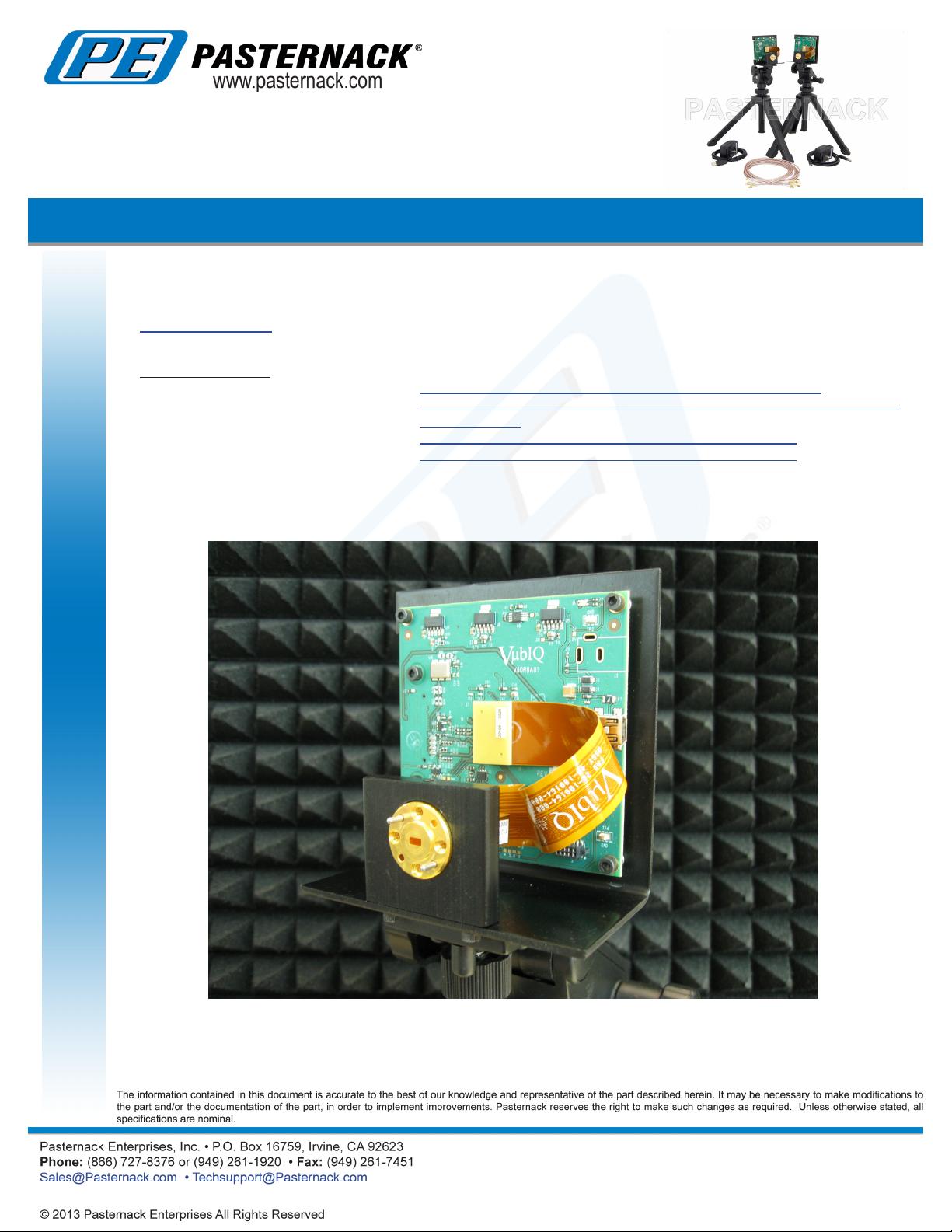
PEM003-KIT
Board Assembly on Tripod Waveguide Module
Potential applications range from multi-gigabit communications systems such as GigE wireless LAN, 802.15.3c, 802.11ad
development, SDI video products, radar, and radiometery. The 60 GHz spectrum is now allocated as unlicensed in many
countries world wide.
Click the following link (or enter part number in “SEARCH” on website) to obtain additional part information including price,
inventory and certications: 60 GHz Transmit/Receive (Tx/Rx) Development System PEM003-KIT
PEM003-KITS REV
3

60 GHz Transmit/Receive (Tx/Rx) Development System
USER GUIDE
International Unlicensed Spectrum Allocation for the 60 GHz Band
Development System Contents
The PEM003-KIT contains the following:
• Transmitter Waveguide Module PEM001
• Receiver Waveguide Module PEM002
• Transmitter board (1)
• Receiver board (1)
• Board/waveguide module mounting bracket (2)
• Bench top tripod (2)
• USB cable (2)
• GUI software (downloadable from web site)
• Documentation and data sheets (downloadable from web site)
• MCX coaxial connector expansion board (2)
• Power Supply (2)
• Phased matched coaxial cables, MCX to SMA (8)
The transmitter and receiver boards are shipped attached to the mounting brackets. The brackets accept a standard ¼-20
thread fastener for use with included tripods.
PEM003-KIT
Click the following link (or enter part number in “SEARCH” on website) to obtain additional part information including price,
inventory and certications: 60 GHz Transmit/Receive (Tx/Rx) Development System PEM003-KIT
PEM003-KITS REV
4
60 GHz Transmit/Receive (Tx/Rx) Development System
USER GUIDE
System Setup / Interconnection
The development system boards communicate with a PC (running the GUI software) using USB as the interface. Each board
derives its power from the USB connection (standard operation). The control processor on each board communicates with
the PC through the USB port.
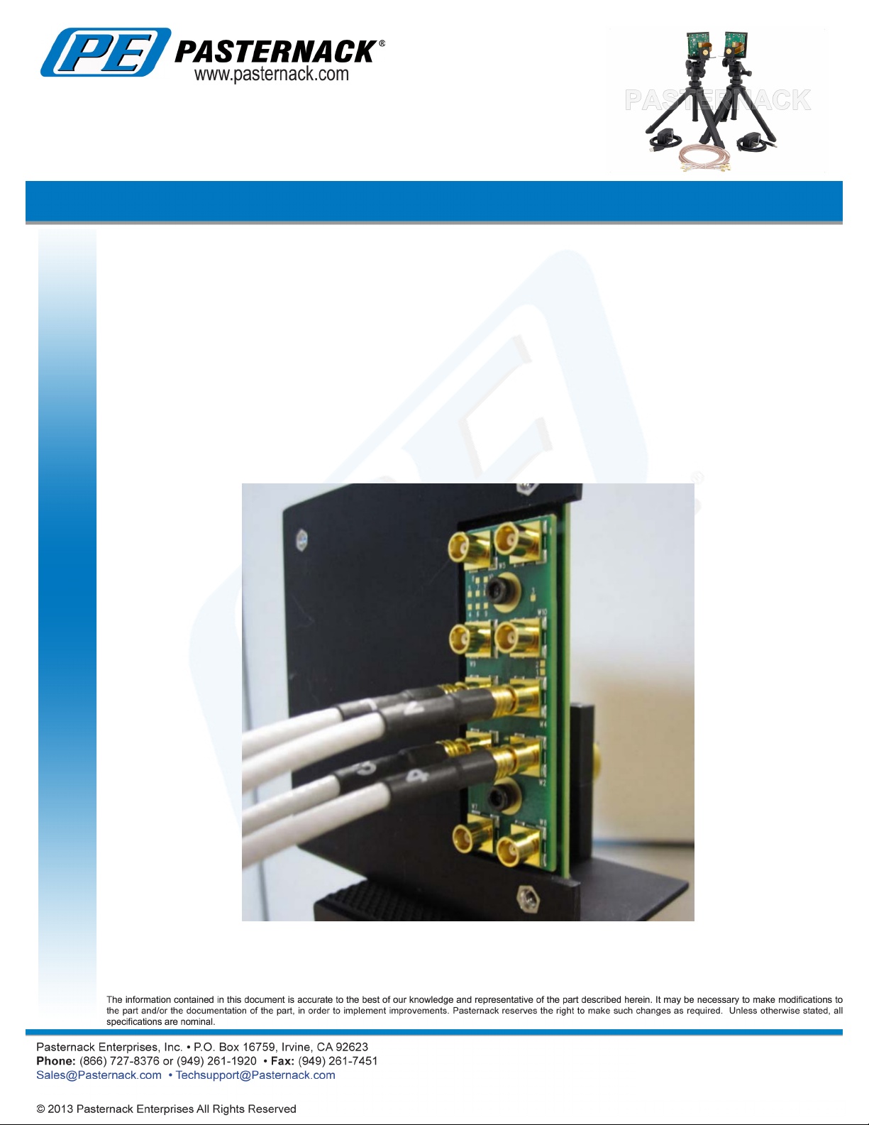
Baseband signals are connected via the high speed baseband connector on the rear side of each board. The baseband
connector is a Samtec QSE. The mating connector required is a Samtec QTE-020-01-L-D-A. The expansion board mounts
onto the Samtec QSE connector and is attached to the main board with the suplied hardware, 2 x 4-40 socket head screws.
The expansion board transitions the QSE connector to a set of MCX coaxial connectors for baseband and optional external
reference clock signals (see Figure 1). Also supplied with the expansion board is a set of eight phase-matched cables for
baseband test equipment interconnection.
PEM003-KIT
Click the following link (or enter part number in “SEARCH” on website) to obtain additional part information including price,
inventory and certications: 60 GHz Transmit/Receive (Tx/Rx) Development System PEM003-KIT
PEM003-KITS REV
5

60 GHz Transmit/Receive (Tx/Rx) Development System
USER GUIDE
Figure 1 RF Board Rear View with Expansion Board Attached
Figure 2 Baseband High Speed Connector and Expansion Board Connectors
PEM003-KIT
Figure 2 shows the pinout of the high speed baseband connector and the expansion board coaxial connectors. For higher
level system integration, direct connection via the Samtec high speed connector can be facilitated using the mating Samtec
connector as shown.
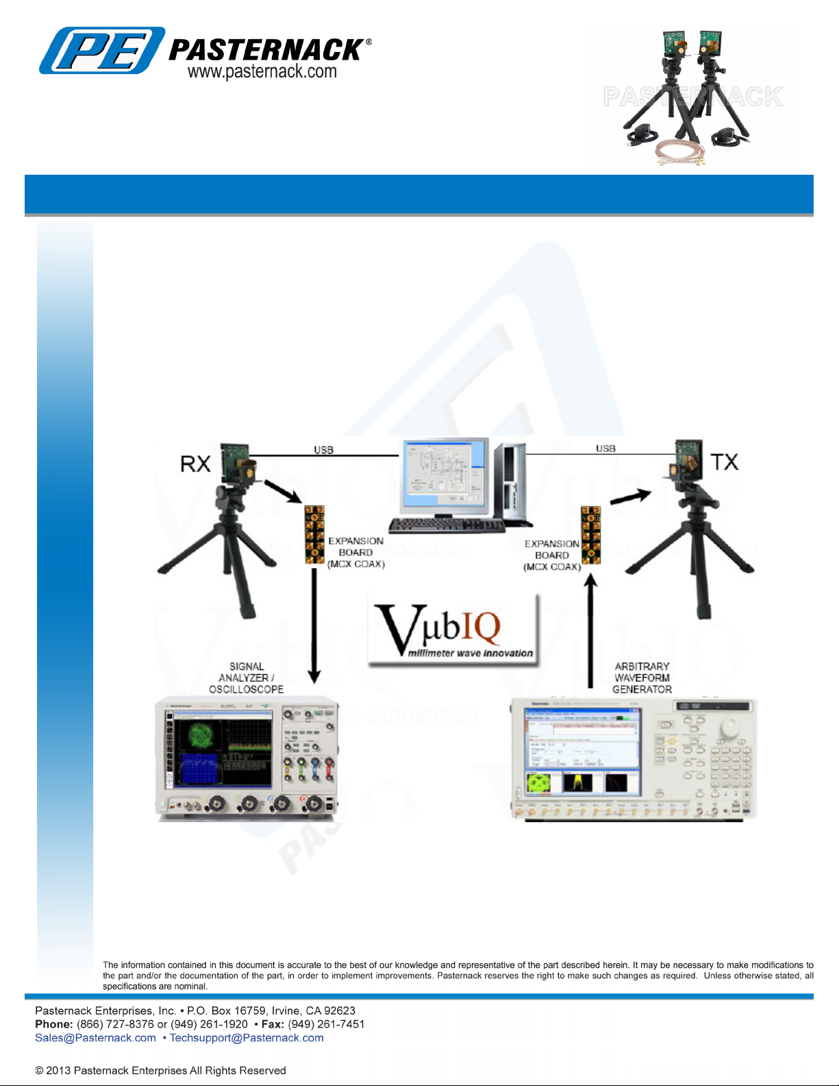
A typical test set up is shown in Figure 3 below. Here the transmitter baseband source is either a user designed baseband
system, or a programmable arbitrary waveform generator (AWG). A two channel AWG can create any form of vector modulation
(I and Q baseband) with appropriate programming or selectable standard modulation formats (such as BPSK, QPSK, etc.).
The receiver baseband scheme is again either user dened or a signal analysis test system.
By using a programmable AWG for the transmitter baseband source, user dened vector modulation schemes can be created
along with various error correction coding, equalization testing, etc. Most AWG products available today work with MATLAB
and other tools that provide a convenient method of baseband signal generation.
Click the following link (or enter part number in “SEARCH” on website) to obtain additional part information including price,
inventory and certications: 60 GHz Transmit/Receive (Tx/Rx) Development System PEM003-KIT
PEM003-KITS REV
6
60 GHz Transmit/Receive (Tx/Rx) Development System
USER GUIDE
GUI Control Software
As shown in Figure 3, the transmitter and receiver boards are set up and controlled from a host PC running the GUI software.
The software can be downloaded using this link as a ZIP le. Unzip the les and place into a convenient directory on the
PC that will be used with the development system test setup. With a transmitter and receiver board connected via the USB
cables to the PC, run the software (VubiqGUI.exe). A transmitter window and a receiver window will appear showing the block
diagrams. The transmitter board LED will illuminate red, and the receiver LED will illuminate blue.
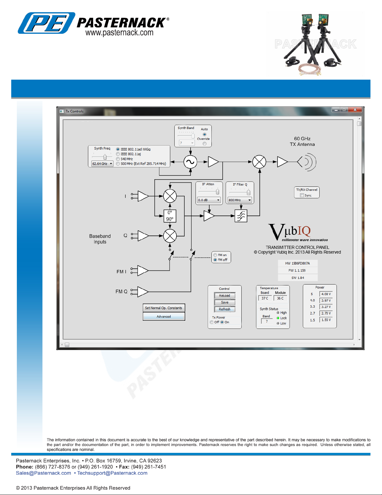
Each GUI window provides the user with the ability to set up various control parameters for the transmitter and receiver boards.
Board voltages and temperatures are also monitored. The window images are shown on the following pages, Figures 4 and 5.
PEM003-KIT
Figure 3 Various Test and Development Scenarios
Click the following link (or enter part number in “SEARCH” on website) to obtain additional part information including price,
inventory and certications: 60 GHz Transmit/Receive (Tx/Rx) Development System PEM003-KIT
PEM003-KITS REV
7
60 GHz Transmit/Receive (Tx/Rx) Development System
USER GUIDE
PEM003-KIT
Figure 4 Transmitter GUI Window
Click the following link (or enter part number in “SEARCH” on website) to obtain additional part information including price,
inventory and certications: 60 GHz Transmit/Receive (Tx/Rx) Development System PEM003-KIT
PEM003-KITS REV
8

60 GHz Transmit/Receive (Tx/Rx) Development System
USER GUIDE
PEM003-KIT
Figure 5 Receiver GUI Window
Click the following link (or enter part number in “SEARCH” on website) to obtain additional part information including price,
inventory and certications: 60 GHz Transmit/Receive (Tx/Rx) Development System PEM003-KIT
PEM003-KITS REV
9
60 GHz Transmit/Receive (Tx/Rx) Development System
USER GUIDE
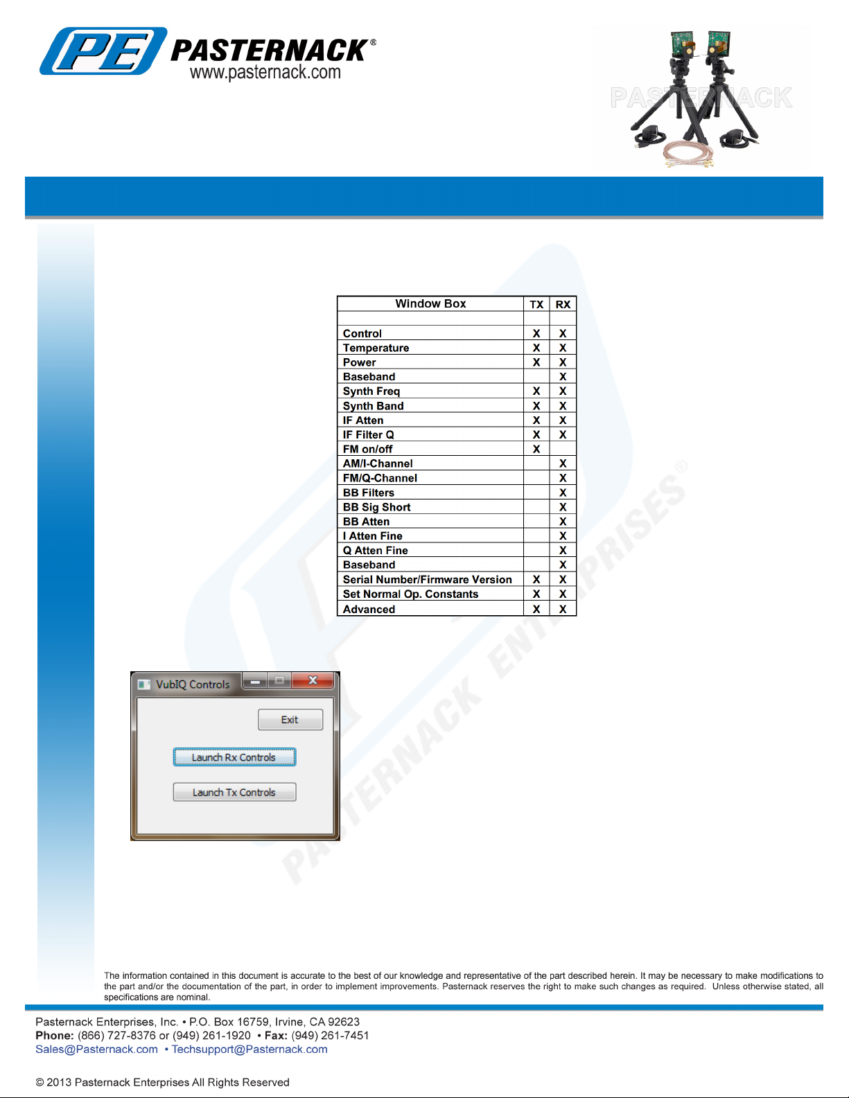
The window layouts are designed as intuitive block diagrams of the transmitter and receiver waveguide module circuits. There
are separate boxes for control and monitoring functions. The following chart (Figure 6) shows the transmitter and receiver
functions for each box.
PEM003-KIT
Figure 6
The window shown to the left is used to exit the GUI entirely and is generated when
the GUI is initialized from the executeable. Disregard the “Launch Rx Controls” and
“Launch Tx Controls” buttons as these two windows are automatically launched by
GUI initialization.
Click the following link (or enter part number in “SEARCH” on website) to obtain additional part information including price,
inventory and certications: 60 GHz Transmit/Receive (Tx/Rx) Development System PEM003-KIT
PEM003-KITS REV
10
60 GHz Transmit/Receive (Tx/Rx) Development System
USER GUIDE
PEM003-KIT
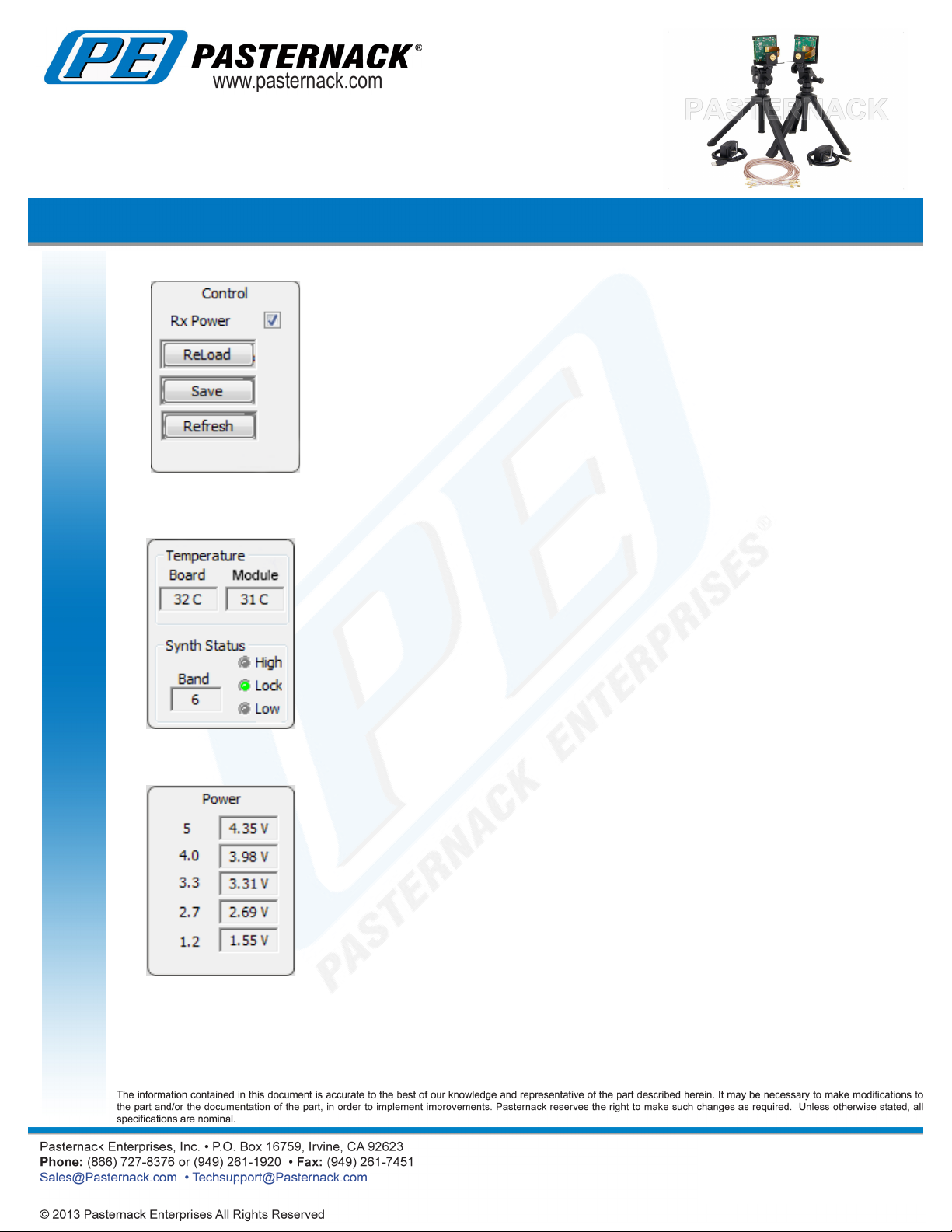
The Control box (RX shown) provides basic controls for the board which includes
following functions:
• Power on/off for the waveguide module
• Reload parameters from FLASH memory
• Save current parameters to FLASH memory
• Refresh GUI display
Note: upon power up, the last set of parameters saved to FLASH memory are used
to congure the transmitter or receiver.
The Temperature/Synth box monitors the board temperature and the RF module
temperature in ºC. The synth status section indicates the synthesizer lock status
and the band tuning status.
Power supply voltages are monitored in this box. Note: the 5 volt supply is measured
from the USB source and typically runs at about 4.1 to 4.4 V.
Click the following link (or enter part number in “SEARCH” on website) to obtain additional part information including price,
inventory and certications: 60 GHz Transmit/Receive (Tx/Rx) Development System PEM003-KIT
PEM003-KITS REV
11
60 GHz Transmit/Receive (Tx/Rx) Development System
USER GUIDE
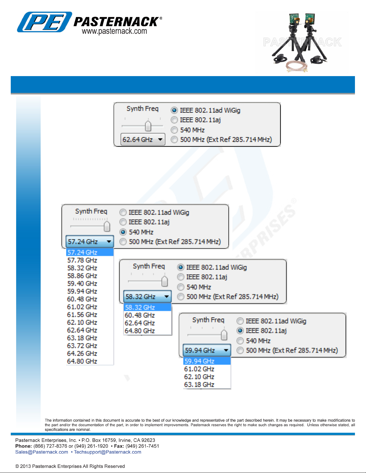
The module’s operating frequency is set with the Synth Freq box shown above. This control sets the synthesizer digital divisor
ratio in the RF module. The standard frequency range can be set from 57.24 GHz to 64.80 GHz in 0.54 GHz steps. Optionally,
the RF modules can be set from 57.0 GHz to 64.0 GHz in 0.5 GHz steps with a reference oscillator clock of 285.714 MHz.
The synth frequency box has pre-congured frequency subsets corresponding to 802.11ad/WiGig, 802.11aj, or xed spacing
at 540 MHz (optionally 500 MHz). The frequency can be selected with either the slider control or the drop down menu.
Occasionaly, when selecting a frequency, the module may not respond to the rst requested input. This can me remedied by
selecting the desired frequency from the drop down menu a second time.
PEM003-KIT
Click the following link (or enter part number in “SEARCH” on website) to obtain additional part information including price,
inventory and certications: 60 GHz Transmit/Receive (Tx/Rx) Development System PEM003-KIT
PEM003-KITS REV
12
60 GHz Transmit/Receive (Tx/Rx) Development System
USER GUIDE
PEM003-KIT
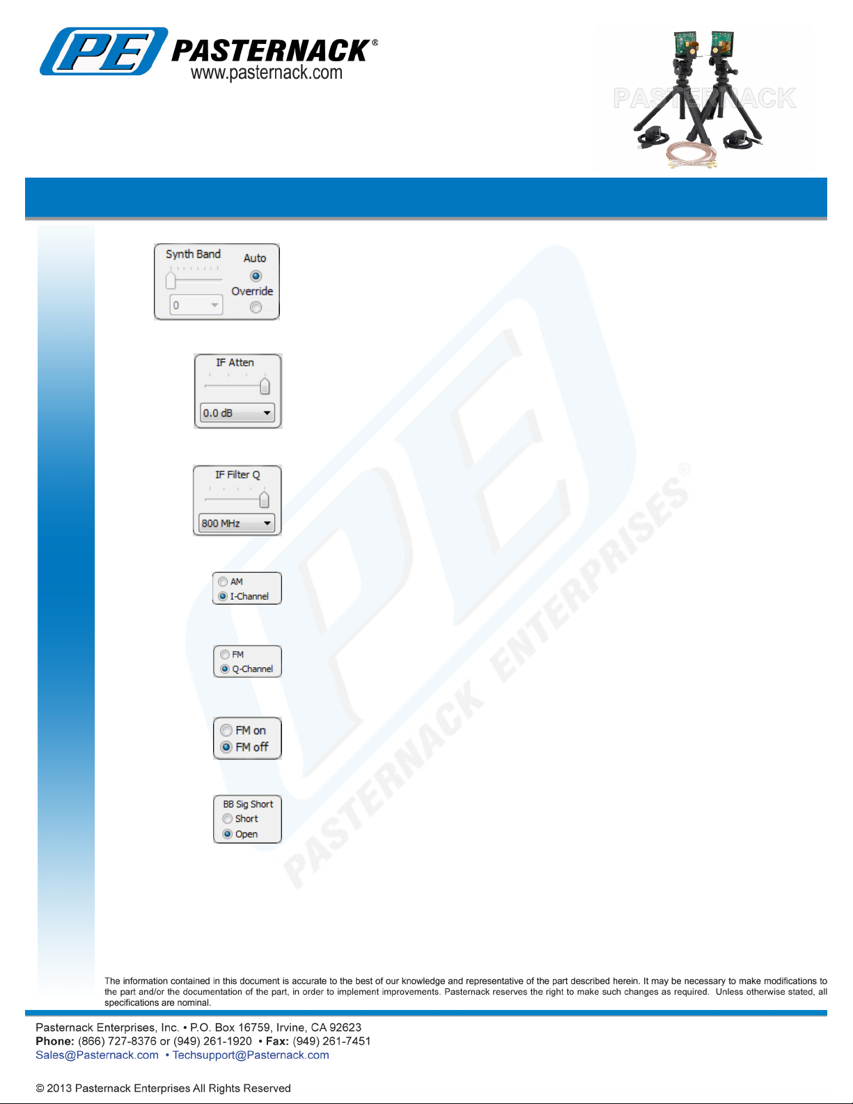
The Synth Band box is typically set in Auto mode, and will track the Synth Freq settings. This
box allows separate tuning adjustment of the VCO tank circuit for experimentation (Override
Mode).
IF Atten box sets the IF attenuation for either the TX or RX board. The lower the attenuation
level (in dB), the higher the gain setting. When this control is set to 0.0 dB, the IF gain is at
maximum. The slider control or drop down menu can be used; there are 16 settings from 0
dB to 20 dB.
The IF Filter Q box is a coarse IF bandwidth control, providing highest Q (narrowest bandwidth)
at 800 MHz, and lowest Q (widest bandwidth) at 1.2 GHz. There are 5 settings from 800 MHz
to 1.2 GHz
The AM / I-Channel control box (RX only) selects the I-channel demodulator (default) or the
AM detector. When the AM detector is selected, its output signal is routed through the I
baseband channel.
The FM / Q-Channel control box (RX only) selects the Q-channel demodulator (default) or
the FM detector. When the FM detector is selected, its output signal is routed through the Q
baseband channel.
The FM on/off control box (TX only) activates the additional FM switching modulators in the I/Q
modulation stage. When selected, FSK type modulation can be set up by using the FMI and
FMQ baseband signal inputs in conjunction with the I and Q signal inputs
The baseband signals can be removed from the output stages (effectively shorted to ground)
using the BB Sig Short box (RX only). This feature may be helpful during testing if no signals
are desired (quiet channel) at the baseband outputs.
Click the following link (or enter part number in “SEARCH” on website) to obtain additional part information including price,
inventory and certications: 60 GHz Transmit/Receive (Tx/Rx) Development System PEM003-KIT
PEM003-KITS REV
13

60 GHz Transmit/Receive (Tx/Rx) Development System
USER GUIDE
PEM003-KIT
The bandwidth of the two baseband channels can be set with the BB Filters box (RX only).
The high frequency roll off selection (HI) is set with either its slider control or the drop down
menu (settings at 200 MHz, 300 MHz, 500 MHz and 1.4 GHz). The low frequency roll off
selection (LO) is set with either its slider control or drop down menu (settings at 30 kHz, 300
kHz and 1.5 MHz). Note: these lters are very broad, approximately 2nd order Butterworth
response.
The BB Atten box (RX only) is used to set the gain of the baseband ampliers. The lower the
attenuation level (in dB), the higher the gain setting. When this control is set to 0.0 dB, the
baseband gain is at maximum. The slider control or drop down menu can be used; there are
7 settings from 0 dB to 36 dB
There are two attenuators for ne gain adjustment of the I and Q channels, the I Atten Fine and
Q Atten Fine boxes (RX only). These provide a convenient method for balancing the I and Q
receive baseband levels or for ne adjustment in 1 dB steps. The slider controls or drop down
menus can be used to adjust the attenuation in 1 dB increments from 0 dB to 5 dB (6 settings).
These two controls, common to the TX and RX, are used to reset the default register data to
the RF modules (Set Normal Op. Constants) and to bring up a detailed RF module register
screen (Advanced).
Each transmitter board and receiver board has a unique serial number (HW). Also, the
rmware release version (FW) and the software release version (SW) are shown in the same
box.
1
The Advanced screen provides access to individual data registers for the RF modules. Changing these register values
through the Advanced screen is not normally required since the GUI interface provides the most comonly used control functions.
Click the following link (or enter part number in “SEARCH” on website) to obtain additional part information including price,
inventory and certications: 60 GHz Transmit/Receive (Tx/Rx) Development System PEM003-KIT
1
PEM003-KITS REV
14
60 GHz Transmit/Receive (Tx/Rx) Development System
USER GUIDE
Reference Oscillator Source Options
The transmit and receive boards come with built-in low phase noise crystal oscillators that provide the clock reference frequency
for the TX/RX synthesizers. The frequency of the on-board oscillator is 308.571 MHz (540 MHz channel spacing) and has a
stability rating over temperature of 25 ppm. There may be certain system level applications that require the transmitter and/or
receiver to be phase locked to an external source. Also, if 500 MHz channel spacing is desired, the external reference clock
must be 285.714 MHz. The TX/RX RF boards are set up to provide the following options for oscillator reference source:
1. Internal, separate crystal oscillators (default)
2. External 308.571 MHz or 285.714 MHz signal source such as a laboratory signal generator (0 dBm typcal
3. Transmitter sourcing the receiver (TX master/RX slave) from the TX on board oscillator
The optional reference oscillator settings are implemented via zero-ohm resistor (or wire jumper) modications on the TX and
RX RF boards as required. The schematics and pictures on the following pages are provided to illustrate the modications for
the desired settings (Figures 7 through 10).
PEM003-KIT
Click the following link (or enter part number in “SEARCH” on website) to obtain additional part information including price,
inventory and certications: 60 GHz Transmit/Receive (Tx/Rx) Development System PEM003-KIT
PEM003-KITS REV
15

60 GHz Transmit/Receive (Tx/Rx) Development System
USER GUIDE
Figure 7 Transmit Board Reference Oscillator Congurations
PEM003-KIT
Figure 8 Transmit Board Reference Oscillator Resistor Locations
Click the following link (or enter part number in “SEARCH” on website) to obtain additional part information including price,
inventory and certications: 60 GHz Transmit/Receive (Tx/Rx) Development System PEM003-KIT
PEM003-KITS REV
16

60 GHz Transmit/Receive (Tx/Rx) Development System
USER GUIDE
Figure 9 Receive Board Reference Oscillator Congurations
PEM003-KIT
Figure 8 Receive Board Reference Oscillator Resistor Locations
Click the following link (or enter part number in “SEARCH” on website) to obtain additional part information including price,
inventory and certications: 60 GHz Transmit/Receive (Tx/Rx) Development System PEM003-KIT
PEM003-KITS REV
17

60 GHz Transmit/Receive (Tx/Rx) Development System
USER GUIDE PEM003-KIT
60 GHz Transmit/Receive (Tx/Rx) Development System from Pasternack Enterprises has same day shipment for domestic
and International orders. Our RF, microwave and ber optic products maintain a 99% availability and are part of the broadest
selection in the industry.
Click the following link (or enter part number in “SEARCH” on website) to obtain additional part information including price,
inventory and certications:
URL: http:// www.pasternack.com/60-ghz-test-development-system-pem003-kit-p.aspx
60 GHz Transmit/Receive (Tx/Rx) Development System PEM003-KIT
PEM003-KITS REV
18
 Loading...