

Page 1
Version 1.1 - 1 -
USER GUIDE
RF&KEYPAD INTEGRATED
LOCKER LOCK
(model :PT400B)
Page 2

Version 1.1 - 2 -
Table of Contents
1 Understanding PT400B Locker Lock ......................................... 3
1.1 What is PT400B Locker Lock? .............................................................. 3
1.2 Operation cards .................................................................................... 3
2. Types of Lock Operating Scenario ......................................... 3
2.1 Free Selection (Shared Use) ................................................................. 4
2.2 Assigned Mode (Permanent Use) ......................................................... 4
3. Lock Operation .......................................................................... 4
3.1 Assigned Mode ..................................................................................... 5
3.2 Free Selection Mode .......................................................................... 5
3.3 Open in Emergency ............................................................................ 6
3.4 Low Battery warning and battery change ........................................... 7
4. Card Operation .......................................................................... 8
4.1 Owner Card ........................................................................................ 8
4.2 Master Card ........................................................................................ 9
4.2.1 Functions of the Master Card I & II .......................................................... 9
4.2.2 Replacing old Master cards with New Master cards ................................ 9
4.3 User Card ......................................................................................... 10
4.3.1 Free Selection (Shared Use) ................................................................... 10
4.3.2 Assigned Mode (Permanent Use) ............................................................ 11
4.3.3 Replacing old User card with New User card ........................................ 11
4.4 Maintenance card ............................................................................. 12
4.5 Audit Trail card ................................................................................. 12
4.6 Lock Info card ................................................................................... 12
5. Indication Instruction .............................................................. 12
ANNEX A Beep & LED Table ........................................................ 13
ANNEX B Trouble Shooting ......................................................... 15
Page 3
Version 1.1 - 3 -
1 Understanding PT400B Locker Lock
1.1 What is PT400B Locker Lock?
- PT400B locker lock is operated by either keypads or BLE enabled mobile
device (i.e. smartphone).
- PT400B is the battery power operating standalone RFID lock ( Offline )
1.2 Operation cards
Card
Name
Description
Card
type
Key
card
• Security Key value to be loaded to locks at scanning.
• Then, the locks will accept only the RFID cards which have the same security key
value.
Mifare
1KB
Setup
card
• Lock will be programmed with various options at scanning.
• Setup card can be set from Lock Installation Software (LIS).
Master I
card
• All locks will be open at scanning.
• User card registration in the lock will be deleted and the lock will be ready to
accept new user card.
Master II
card
• Locks will be open or close without User card registration deletion.
• Useful when user needs to open lock temporarily.
Owner
card
• Master cards registration to be deleted at scanning this card on locks.
• After Owner card scanning on lock, scan new master cards to register to the lock.
Mainten-
ance
card
• Lock to be programmed with various options at scanning as you set.
• Time, Master cards registration, Master code, etc can be updated without
changing lock ID.
Audit
trail
card
• Latest 18 event history to be collected at scanning.
• Card number, event type (open & close), time of event, user name, etc to be
collected.
Lock info
card
• Various information of lock can be collected into this card.
• One Lock info card can collect information from up to 100 locks.
• Lock ID, Operation mode, Battery status, software version, time, auto opening and
more to be collected.
Mifare
4KB
2. Types of Lock Operating Scenario
PT400B locker locks are designed to be suitable for various operational requirements
Page 4
Version 1.1 - 4 -
by simple set up process. Following operation modes can be programmed before or
after lock installation.
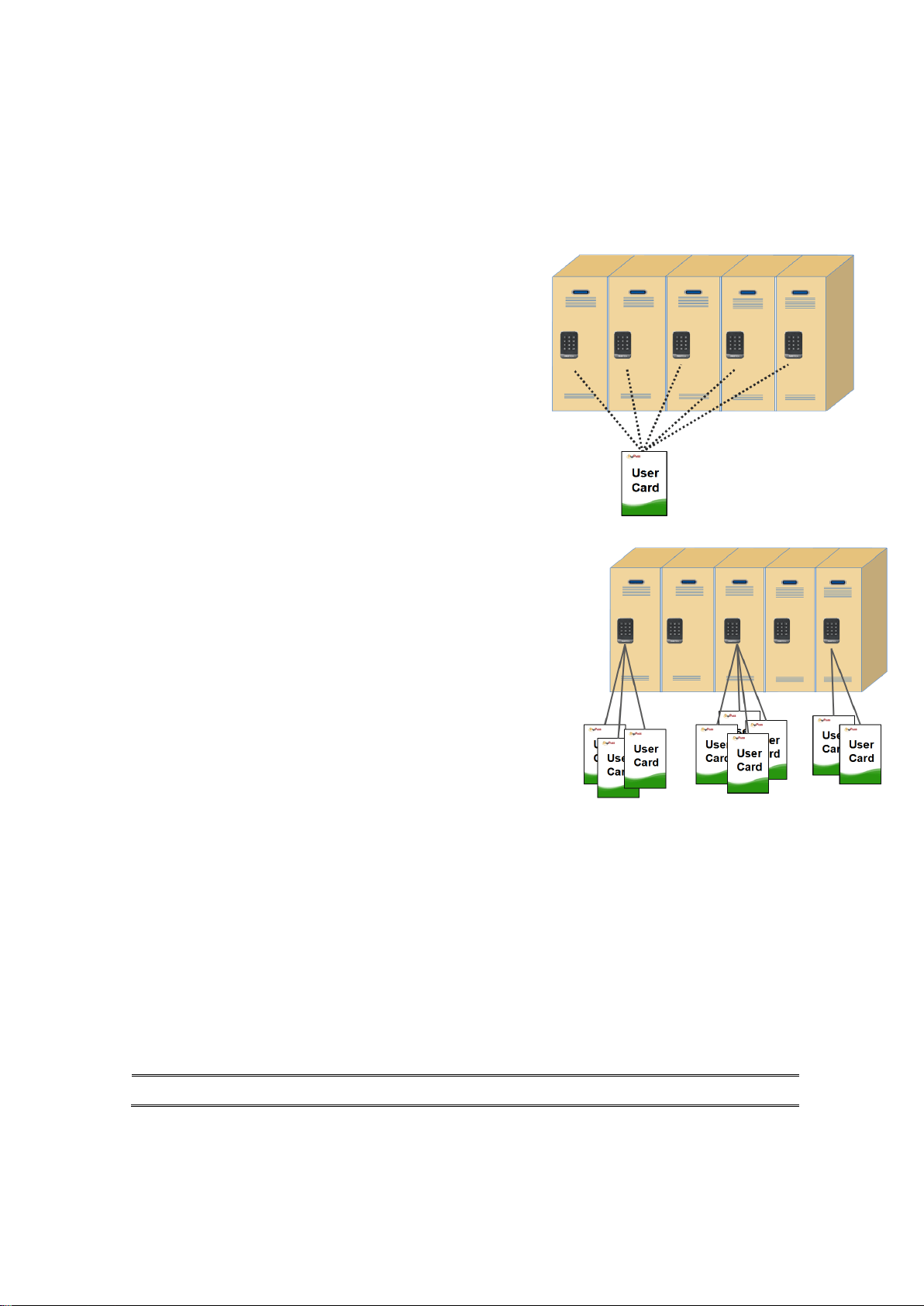
2.1 Free Selection (Shared Use)
- User can select any empty locker.
- LED lamp is blinking to represent locker is in use.
- Programmable to use multiple locks with one
User card (max. 8 users in a locker).
- Programmable for Time based operation
2.2 Assigned Mode (Permanent Use)
- Locker assigned to each User card in advance.
- Programmable to use multiple assigned lockers
with one card (max. 5 lockers ).
- Programmable for multiple user mode per a locker
(max. 8 users in a locker).
3. Lock Operation
PT400B can be accessed with both Pin and BLE enabled smartphone.
Page 5
Version 1.1 - 5 -
3.1 Assigned Mode
3.1.1 Open & Close by Pin Code
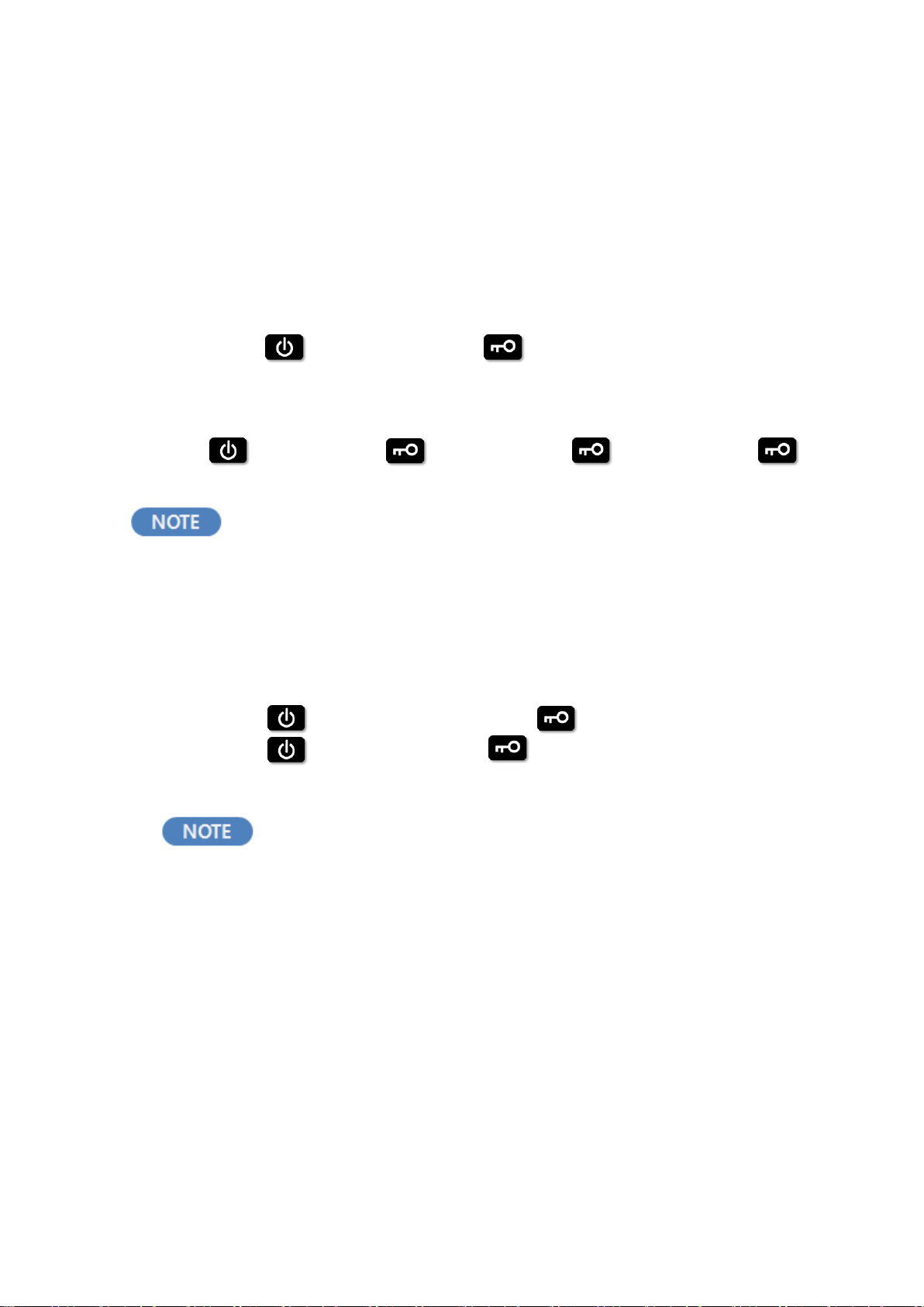
① Default Pin Code :1234
② Open: + “4 digit Pin Code”+
③ Close: Automatic close after several seconds ( Full cycle latch )
④ Change Pin Code:
+ old Pin Code + + new Pin Code + + new Pin Code +
Pin Code can be changed only when the lock is under
unlocked status.
3.2 Free Selection Mode
3.2.1. Open & Close by Pin Code
① Close: + self-selected 4 digit code +
② Open: + User’s 4 digit code +
After it is unlocked, any 4-digit password can be used to lock it.
User Pin Code will be deleted each time lock is opened.
3.2.2. Open & Close by Smartphone
(1) How it works
Page 6

Version 1.1 - 6 -
① Download Passtech Mobile App from Google play store and install it into his
smartphone
② After running the App, choose ‘Free mode’ on the setting tab.
③ Then, you can freely choose any available lock to operate.
(2) Access Log
To check the history of the mobile access key, visit the “Access Log” panel in
the Menu window.
To access your mobile device, please set your
lock for CSN Free mode and change the usage mode to Free
mode from the Passtech APP from your mobile device.
3.3 Open in Emergency
① In case User forgets his(her) password or lost card, Operator can open the
Page 7

Version 1.1 - 7 -
lock by Master Card I or Master code.
② If Master code is set, + Master code + to open any locks.
Master card can be set by Set up Card.
③ Once Master card I is used to open the lock, the lock reverts to default
position
(i.e. lock will stay open for Free Selection, and default code of 1234 for
Assigned mode.).
④ User Card ID will be erased from the lock if Master Card I has the function
to delete the User ID.
⑤ When the lock stops working due to low battery, lock can be opened by
external emergency battery pack.
3.4 Low Battery warning and battery change
The RFID lock uses 4 pieces of 1.5V AA alkaline batteries (6V).
(1) When battery reaches to low voltage ;
① Beep sounds five times.
② Red LED lights
③ Low battery is recorded in the memory of the User Card (Operator can know
the low battery of the lock when the card is read at operator’s Program).
(2) Changing battery
① Open the battery case at main case.
② Replace with new batteries.
③ When you replace batteries, do not mix the brands of them and use only brand
new batteries.
④ When you pull out the battery, and if you do not insert the batteries in 3 minute,
the clock of the lock returns to default time.( 1st. Jan, 2010 )
⑤ Please use Maintenance card to set the time of the lock.
(For setting of Maintenance card, please refer to LOS (Locker Operation
System) User Manual or Esmart ultra client user manual.
CAUTION
Page 8

Version 1.1 - 8 -
RISK OF EXPLOSION IF BATTERY IS REPLACED
BY AN INCORRECT TYPE.
DISPOSE OF USED BATTERIES ACCORDING
TO THE INSTRUCTIONS
4. Card Operation
4.1 Owner Card
The role of the Owner card is to delete the Master card registration. Therefore, Owner
Page 9

Version 1.1 - 9 -
card will be used to delete current master card registration in the lock, and make the
lock to be ready to register new Master Card.
It is simple to delete the Master card registration and to register new master card in
the lock :
① Put the Owner card to the lock until lock sounds beep (one time) and red lamp
lights.
② Now, all Master card registration is deleted from the lock.
③ After Owner card scanned, put new master cards to register to the lock
4.2 Master Card
4.2.1 Functions of the Master Card I & II
① There are two types of Master cards.
◆ Master card I : Alarm Off, Locker open and User card deletion.
Useful card at user card lost.
After Master card I scanned on a lock, the lock is ready to
accept new user card.
◆ Master Card II : Alarm Off and Locker open and close.
Useful card for temporary lock open or close.
Previous user card is still assigned to the lock.
② Maximum five Master cards can be registered in a lock.
4.2.2 Replacing old Master cards with New Master cards
There are two ways to delete the lost Master card and register new Master card in
the lock.
(1) Using Maintenance Card
① Read the master cards (all Master cards to be used in a lock) to register
in each lock at Maintenance menu in LOS program
② Put the Maintenance card to the reader, and download the master card
chip numbers to the Card.
Page 10

Version 1.1 - 10 -
③ Put the Maintenance card to the locks, then, new Master cards will be
registered to the lock, and lost master card will be blocked.
(2) Using Owner Card
① Delete the old master card registrations in the lock (refer to the 4.1) with
Owner Card.
② Put new master cards to each lock so as to register new master cards.
Then, old master card you lost will not be used.
☞ All existing Master cards needs to be registered again together with new
Master card because all master card registrations were deleted if Owner card
is used.
4.3 User Card
4.3.1 Free Selection (Shared Use)
The initial status of the lock in Free Selection mode is open (Latch is inside).
(1) Initial Use
① Select the empty locker.
② Put your belongings in the locker.
③ Press on the front body of the lock to wake up the lock, and place your
card (or any form of user key) to the front body of the lock.
④ Wait until the Green LED lights and Beep sounds once.
⑤ Bolt will move out, and lock is closed.
⑥ Close the door, and the lock will be remained at locking state.
(2) Open the lock
① Press on the front body of the lock.
② Put close your card to the front body of the lock.
③ Lock will check the lock ID and key of the user card (or any form of user key).
④ Lock will emit Green LED and beep sound once it is right user card .
⑤ Bolt will be moved and locker will open.
⑥ User information will be erased from the lock so that new user can use the
empty lock.
Page 11

Version 1.1 - 11 -
☞ In free selection mode, lock and card needs to read and write the each
other’s information. So please do not sway the card until the latch is moved.
4.3.2 Assigned Mode (Permanent Use)
The initial status of the lock in Assigned Mode is closed status (bolt out)
① Press on the front body of the lock.
② Put the User Card to the front body of the assigned lock.
③ Lock checks the card, and green LED lights and beep sound once. Then, lock
will be opened, and closed again in 5 seconds.
④ To close the locker, just close the door. Lock will remain the closed status.
4.3.3 Replacing old User card with New User card
(1) Free Selection
① Issue new user card by LOS (Locker Operation System) program.
② In case the locker is closed, put Master Card to the lock to open the lock.
③ Put new User card to the lock, then lock will accept new User card, and missing
card will not be accepted.
④ In case the locker is opened, just put the new user card to the lock, and the
lock will register this locker number. Old User key will not be accepted.
(2) Assigned Mode
① Issue new User card (with assigned locker Number) for Assigned mode.
② Put Master Card to the lock to delete the old user card, and put the new User
card to the lock.
③ Lock will accept the new user card only, and old user card registration will be
deleted.
④ In case the lock is set for multiple users, lock revision should be updated when
new user card is issued by LOS program. Then, Lock updates it’s revision
number when new user card is scanned. The other user cards which are
assigned to this locker also needs to be reissued with updated lock revision by
LOS program.
Page 12

Version 1.1 - 12 -
4.4 Maintenance card
① Program Maintenance card as you want from LOS
② Put Maintenance card to each lock, lock will be set as you programmed in
step ①
③ Time of the lock, Master cards change, Master code, Wireless online channel,
Auto status update time can be updated with Maintenance card.
4.5 Audit Trail card
① Put Audit Trail Card to the lock.
② The latest event data (up to 18 events) will be downloaded from lock to the
Card. Wait until melody is on.
③ Read the Card at LOS program, and 18 event data will be saved to the PC.
4.6 Lock Info card
① Put Lock info Card to the lock.
② Various lock information data will be downloaded from locks to the Card. One
card can collect up to 120 locks.
③ Read the Card at LOS program, and all data will be saved to the PC.
④ Lock ID, operation mode, Battery status, time, auto opening setting status, RF
channel and more will be indicated.
For further information about all system cards and how to issue,
refer to LMS / LOS manual.
5. Indication Instruction
1) All the Pin Code is 4 digit(0-9).
2) : wake up button,the keypad or RFID does not respond before
you press this button.
Page 13
Version 1.1 - 13 -
3) Open/Close:GREEN LED on for 0.2 second, one beep sound for 0.2
second.
4) Successful programming:Melody.
5) Indicate for mistake:RED LED flashes 3 times, 3 beep sounds
6) Low voltage:RED LED blinks 5 times, and beep sounds 5 times.
7) Incorrect Pin Code or input is beyond 6 digits: see #5, power off,need
to press to wake up the keypad again.
8) When the input is incomplete, after 5 seconds, see #5,power off .
You need to press again to wake up the keypad.
ANNEX A Beep & LED Table
Beep
LED
Description
1 x short beep
1 x Green
OK
3 x short beep
3 X Red
1)Operation Error
Time over or push more than 6 digit
Page 14

Version 1.1 - 14 -
buttons
3 X short beep
1 X Green & Red
User card expired
4 X short beep
-
Exceed the capacity of Lock info card
5 x short beep
5 x Red & Green
Low battery
Do-Re for 1.5 sec
4 X Red & Green
Forced entry. Latch moved without
proper authentication
3 X Do-Re
-
Latch open failure
Do-Mi-Sol-Pa Melody
1 X Green
Operation card and User card
registration or operation Successful
Correct pin code or pin code change
successful
Do-Mi-So-Pa Melody
3 x Red & Green
Successful connection between front
and bodies.
5 X Do-Re-Mi
6 X Red & Green
3shift or Lock time limit activated
No Beep
Both Green and
Red LED blinks
1) Owner Card is not registered.
2) In case of Shift or Week-day
operation mode, Alarm for shift or Time
due.
No Beep
Red on/off
Owner card is registered, but Master
card is not registered.
No Beep
Green on/off
Owner & Master card are registered, but
User card is not registered in Assigned
Mode.
Page 15

Version 1.1 - 15 -
ANNEX B Trouble Shooting
Master card registration in the lock
was failed.
1) Master card registration should be followed
after deleting old Master card in the lock by
Owner card.
2) Put Master card on the lock before waiting
time is out after Owner card.
Cannot open the lock with Master
card
Master card is not registered in the lock.
Please Register the Master card in the lock.
Cannot open or close the lock by
User card
1. Check the Setting of User card by LOS.
(1) Free Selection Mode
⚫ Validity / Operation mode / Lock ID /
Number of locks this user card can
be used.
(2) Assigned Mode
⚫ Validity /Operation Mode / Lock ID /
Number of locks this user card can
be used.
2. Reset the time of the Lock with
Maintenance card.
3. Old User card may be still in the memory of
the lock. Erase the card information from
the lock by Clear card, then register again
the Owner card and Control Card, then use
User card.
When is pressed, five beep
sounds with Red lamp.
Low battery sign. Please replace the batteries.
Latch does not move, while Card and
lock operates in normal.
Too many goods may press the lock body or
door. Push the locker door to make the space
for the latch movement.
Page 16

Thank you for choosing PT400B RFID/Keypad locks.
IF you have any questions, please contact your
local distributor or our technical support.
FCC Statement
15.19: This device complies with part 15 of the FCC rules. Operation is subject to the following two conditions: (1) This
device may not cause harmful interference, and (2) This device must accept any interference received, including
interference that may cause undesired operation.
5.21: Note: The grantee is not responsible for any changes or modifications not expressly approved by the party
responsible for compliance. Such modifications could void the user’s authority to operate the equipment.
15.105(b): Note: This equipment has been tested and found to comply with the limits for a Class B digital device, pursuant
to part 15 of the FCC Rules. These limits are designed to provide reasonable protection against harmful interference in a
residential installation. This equipment generates uses and can radiate radio frequency energy and, if not installed and
used in accordance with the instructions, may cause harmful interference to radio communications. However, there is no
guarantee that interference will not occur in a particular installation. If this equipment does cause harmful interference to
radio or television reception, which can be determined by turning the equipment off and on, the user is encouraged to
try to correct the interference by one or more of the following measures:
- Reorient or relocate the receiving antenna.
- Increase the separation between the equipment and receiver.
- Connect the equipment into an outlet on a circuit different from that to which the receiver is connected.
- Consult the dealer or an experienced radio/TV technician for help.
Disclaimers
The manufacturer, importer, and distributor shall not be liable for damages including accidental and personal injury due
to the improper use or operation of this product.
The information in this user manual was written based on current product specifications.
The manufacturer, iriver Limited, is adding new complementary features and will continue to apply new technologies in
the future.
Product specifications may be changed without prior notice.
iriver is not responsible for data loss due to product use.
Exposure statement
The transmitter must not be co-located or operated in conjunction with any other antenna or transmitter. This equipment
complies with the FCC RF radiation exposure limits set forth for an uncontrolled environment. This equipment should be
installed and operated with a minimum distance of 20 cm between the radiator and any part of your body.
Version 1.1 - 16 -
 Loading...