

pass & seymour WDT-200, WDT-100 Installation Instructions Manual
TROUBLESHOOTING
Lights do not turn ON with motion (LED does flash)
1. Pressand release eachbutton to make surethat the correctlights come
ON foreach relay. Ifthe lights doNOT turn ON, checkwire connections,
especiallythe Load connection.If the lightsturn ON, verify thatthe
correctOn Mode is selectedin DIP switches8 and 9.
2. Check tosee if light levelcontrol is enabled:cover the sensorlens with
your hand.If the lights comeON, adjust the lightlevel setting.
3. If lightsstill do not turnON, call 800.223.4185for technical support.
Lights do not turn ON with motion (LED does not flash)
1. Pressand release eachbutton. Make surethat the correctlights come ON
for eachrelay. If thelights turn ON, setPIR and ultrasonicSensitivity to
High.
2. Check thewire connections,in particular, the Neutraland Line
connections.Verify that connections aretightly secured.
3. If lightsstill do not turnON, call 800.223.4185for technical support.
ADJUSTMENTS
Sensor Adjustment
Removethe wall plate. Removethe button cap byfirmly squeezing togetherthe
top sidesof the button assembly.Gently pull it awayfrom the unit.
When theadjustments are completed, replace the buttoncap by insertingits
hinges intothe tabs on themain unit and thensqueeze the top of thebutton
whilepressing it intothe unit. Reinstall thecover plate.
Light Level Adjustment
The lightlevel can be setwith loads ON orOFF. Toenable light levelcontrol and
set thethreshold: 1) Makesure the roomis lit appropriately. 2) Putthe sensor
into TESTmode. You have5 minutes to complete the procedure.3) Press and
hold theON/OFF button (Relay1 button onthe WDT-200) for 3seconds, until
you heara beep. 4) Step awayfrom the sensor. After25 seconds a beepsounds,
indicatingthat the thresholdlevel is set. Thisthreshold is retained, evenif power
is lost,until it is re-setor disabled. Inthe WDT-200, lightlevel control only
affectsRelay 2.
Todisable light levelcontrol, pressand hold the Relay1 button for7 seconds,
until adouble beep tone sounds.
Reset to Default
Toreset the WDT tofactory settings,press and hold theRelay 1 button for
10 seconds,until a triplebeep sounds. This resetsthe sensor occupancyhistory
and disableslight levelcontrol (the brightestambient light willnot hold the light
OFF).
ORDERING INFORMATION
Warranty Information
Pass &Seymour /Legrand warrantiesits productsto be free ofdefects in
materialsand workmanship fora period of five years.There areno obligations
or liabilitieson the part ofPass & Seymour /Legrandfor consequential
damages arisingout of or inconnection with theuse or performance ofthis
productor other indirectdamages with respectto loss of property,revenue, or
profit,or cost of removal,installation orreinstallation.
Units comein White(-W), Light Almond(-LA), Ivory(-I), Gray (-Gry),Black (-BK).
Add colordesignator to catalog numberwhen ordering.
* OneTP26 CoverPlate for singlegang box is includedwith eachswitch.
Syracuse,NY 13221-4822
800.223.4185
www.passandseymour.com
Installation Instructions
Specifications
Voltages:
WDT-100& WDT-200 . .. . . . .. . . .120/230/277VAC, 50/60Hz
Load Limitsfor each relay:
@120VAC .. . . . .. . . .. . .0-800W tungstenor ballast, 1/6HP
@230 or277VAC .. . . .. . . .. . . . .. . . .. . . . ..0-1200W ballast
Load TypeCompatibility:
Incandescent,fluorescent,magnetic or electronicballast
HorsepowerRating (each relay) . . . . .. . . ..1/6 HP @120VAC
Time DelayAdjustment .. . . . .. . . .. . . . .. . . .. .5 to 30 minutes
Walk-Through Mode. . . .3 minutesif no activity after30 sec.
TestMode . .. . 5 sec. at initialpower up or DIPswitch reset
PIR Adjustment .. . . .. . . . .. . . .. . . . ..High or Low (DIP switch)
UltrasonicAdjustment .. . .Minimumto Maximum (trimpot),Off
Frequency. . . .. . . . .. . . .. . . . .. . . .. . . . .. . . . .. . . .. .40kHz
Light LevelAdjustment . . . .. . . .. . . . .. . . . .. . . .. .8fc to 180+fc
Alerts .. . . .. . . . .. . . .. . . . .. . . . .. . . .. . . . ..Selectable Audible
P.O.Box 4822, Syracuse,NY 13221-4822
TechnicalSupport: 800.223.4185• www.passandseymour.com
340892 11934
Catalog # Description
WDT-100 Dual technology wall switchsensor; 120/230/277VAC, 50/60Hz
WDT-200 Dual technology dual relaywall switch sensor;
120/230/277VAC, 50/60Hz
TP126 Toggleswitch and decorator opening wall plate *
US Patents:5189393, 5640113,
6617560B2,A4787722
Lights do not turn OFF
1. Therecan be up to a 30minute time delay afterthe last motionis
detected.To verify properoperation, setDIP switch 1 to ON,then reset
switches1 and 2 to OFF tostart TestMode. Move out of viewof the sensor.
The lightsshould turn OFF inapproximately 5seconds.
2. Verifythat the sensor is mountedat least sixfeet (2 meters)away from
any heating/ventilating/airconditioning devicethat may cause false
detection.Verify that thereis no significantheat source (e.g.,high wattage
light bulb)mounted near thesensor.
3. Verifythat the trimpot isnot pointing at “override”(red LED on).If so,
rotatethe trimpot to it’smiddle setting(pointing up). The overridesetting
allowsusers to operate thesensor as a serviceswitch in the unlikely
event ofa failure.
4. If the lightsstill do not turnOFF, call 800.223.4185for technicalsupport.
Sensing motion outside desired areas
1. SelectPIR Sensitivity – Low(DIP switch 4 = ON)if necessary.
2. Mask thePIR sensor’s lensto eliminate unwantedcoverage area.
3. Adjust theUltrasonic Sensitivity.Rotate trimpotcounterclockwiseto
reducesensitivity.
DELAY
PIR50 %
WALK
TRIGGER
ALERTS
RLY1 MAN
RLY2 MAN
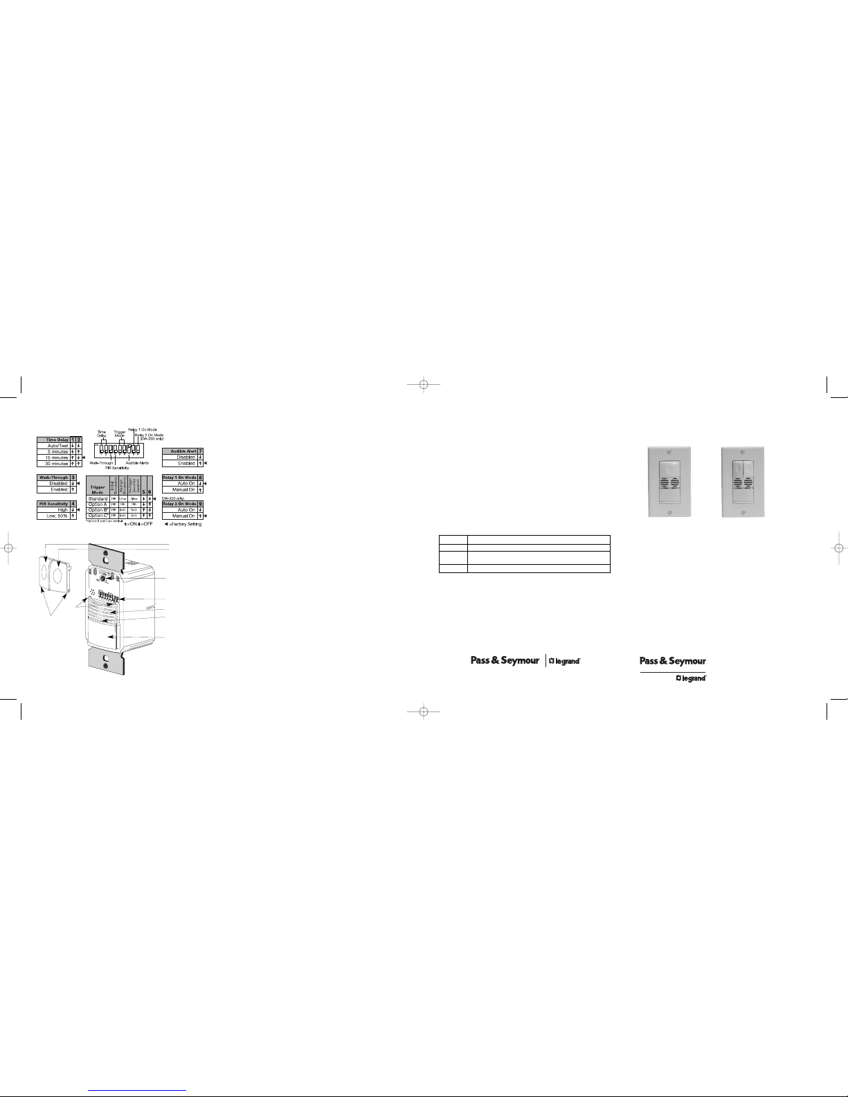
ON/OFF Buttons
Relay 1
Relay 2
DIP Switches
Detection LEDs
Red =PIR
Green =Ultrasonic
PIR Lens
DIP SWITCH SETTINGS
Call 800.223.4185 for Technical Support
Ultrasonic Cones
Ultrasonic Sensitivity
Adjustment Trimpot
Button
Hinges
Tabs
WDT-100/WDT-200
Dual Technology Wall Switch
Occupancy Sensor
WDT-200 shown.
WDT-100 has a
single button and
the Ultrasonic
sensitivity
adjustment trimpot
is in aslightly
different position.
WDT-100
WDT-200
WDT_340892_11934.qxd:340892 11934 WDT_Instruction Sheet 10/12/09 4:08 PM Page 1
Fixed Time Delay
(DIP 1 ON & 2 OFF)
COVERAGE PATTERNS
Coveragetesting has been
performedaccording to the
NEMA WD7 guideline. For best
performance,use in spacesnot
largerthan 18' x 15'.
PIR Sensor
The sensorhas a two-tiered,
multi-cellviewing Fresnellens
with 180degree field of view. The
red LEDon the sensor flashes
when thePIR detects motion.
Masking the lens
Opaque adhesivetape is supplied
so thatsections of the PIR
sensor’sview can be masked.
Youcan eliminate coveragein
unwantedareas. Since masking
removesbands of coverage,take
this intoaccount when troubleshootingcoverage problems.
Ultrasonic Sensor
The sensorhas two ultrasonictransceivers operatingat 40kHz. Detection
sensitivitycan be adjustedusing the trimpot underthe ON/OFF buttons.
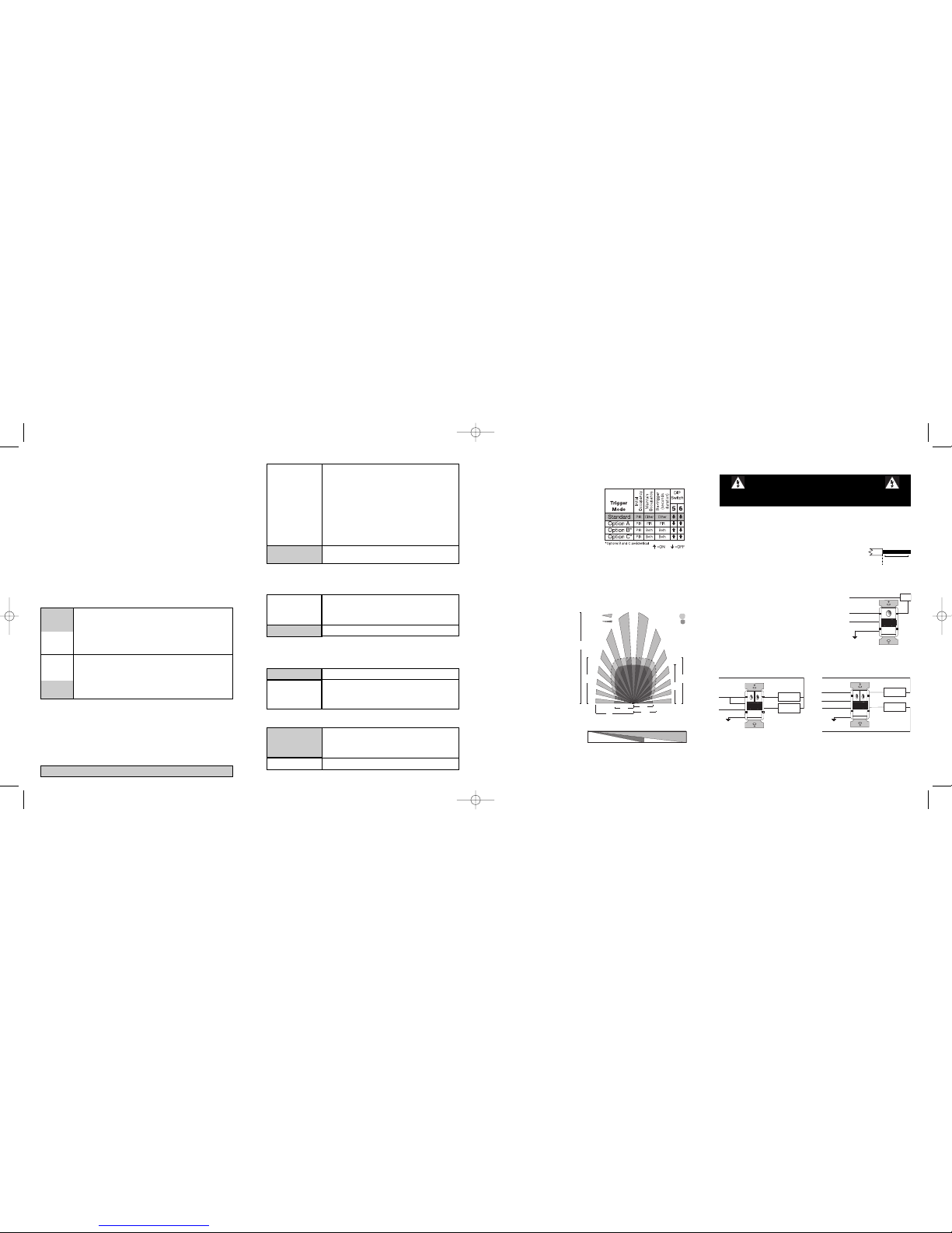
Trigger Mode
The WDTsensor has 4 occupancytrigger options, setwith DIP switches5 and 6.
Determinethe appropriate optionusing the Triggermatrix.
In theTrigger Mode DIP switchsetting table,
in orderto deem the areaoccupied:
• Both requiresmotion detectionby the PIR
and theultrasonic.
• Either requiresmotion detectionby only
one technology.
• PIR requiresmotion detection bythe PIR.
InitialOccupancy: The methodthat activates
a changefrom “Standby” (areaunoccupied
and loadoff) to “Occupied”(area occupied
and loadmay turn on).
MaintainOccupancy: The methodindicating that thearea is still occupiedand
the lightsshould remain on.
Re-trigger:In AutomaticMode, afterthe load turnsoff, detectionby the selected
technologywithin thenumber of secondsindicated turnsthe lightsback on. If the
loadwas turned on withthe ON/OFFbutton, the re-trigger timeis 30 seconds.
Auto ON
DIP 8 OFF
for Relay 1
DIP 9 OFF
for Relay 2
High (DIP #4 OFF)
Walk-Through
Mode
(DIP #3 ON)
The WDTsensor turns the loadOFF 3 minutes after
the areais initially occupied,if no motionis detected
after thefirst 30 seconds.If motion continuesbeyond
the first30 seconds, theset time delay applies.
Alerts
The WDTcan provide audiblealerts as awarning before theload turns OFF.
Defaultsetting. Suitable formost applications.
PIR Sensitivity Adjustment
The WDTsensor constantlymonitors the controlled environmentand
automaticallyadjusts the PIRto avoid commonambient conditions thatcan
cause falsedetections, whileproviding maximumcoverage.
UNIT DESCRIPTION AND OPERATION
The WDTDual TechnologyWall Switch sensorscombine advancedpassive
infrared(PIR) and ultrasonictechnologies intoone unit. The combined
technologieshelp to eliminatefalse triggering evenin difficult applications.
Selectableoperating modesallow the sensor toturn a load on,and hold it on
as longas either or bothtechnologies detect occupancy.After no movement
is detectedfor the selectedtime delay, the lightsswitch off.A “walk-through”
mode canturn lights off afteronly 3 minutes,if no activity is detectedafter
30 secondsfollowing an occupancy detection.
The WDT-100has one relayand one ON/OFF button.The WDT-200 contains
two relaysand two ON/OFFbuttons to allow control ofone or two loads
independently. Pressing a buttontoggles the stateof the corresponding relay.
WDT sensorscontain a lightlevel sensor.If adequate daylightis present, the
sensor holdsthe load OFF untillight levels drop,even if thearea is occupied.In
the WDT-200,light levelonly affects the loadon Relay 2. Userscan override this
functionby pressing the ON/OFFbutton. See LightLevel Adjustment.
Turning The Load ON
The relaysare programmedindependently foreither Auto ON orManual ON. In
either mode,the load can beturned ON or OFFusing the ON/OFF button.
Load turnsON and OFF automatically basedon occupancy. Ifthe
load isturned OFF manually,it stays OFF until5 minutes after
the lastoccupancy detection,at which time it reverts toAuto ON
mode. Thisprevents the loadfrom turning ONautomatically after
it wasdeliberately turnedOFF. Pressingthe button to turnlights
ON returnsthe sensor to AutoON mode.
** WDT-100:Switch 9 is not used.WDT-200: Switch9 default is ON tocomply
with CAEnergy CommissionTitle 24 bi-levelswitching requirements.
Time Delays
The WDTsensor holds the loadON until no motionis detected forthe selected
time delay. Selectthe time delay usingDIP switch settings.The sensor
automaticallysets the timedelay when SmartSet isenabled. In the WDT-200,
both relaysuse the same delay.
Manual ON
DIP 8 ON
for Relay 1
DIP 9** ON
for Relay 2
Occupantsmust press theON/OFF button to turnON the load.
The sensorkeeps the loadON until no motion isdetected for
the selectedtime delay.There is a 30second re-trigger delay.
If occupancyre-triggers duringthe delay (see Trigger Mode),
the sensorturns the load backON. After the re-trigger delay
elapses theON/OFF button mustbe pressed toturn ON the load.
Time delaysof 5, 15 (default),or 30 minutes are
available.See DIP SWITCHSETTINGS for information.
SmartSet™ auto
adjust time delay
and TestMode
Recordstypical occupancypatterns. Using this history
(which isconstantly updated),it chooses an optimal
time delayfrom 7 minutes(if the space is usually
vacant)up to 30 minutes (ifthe space gets heavy
usage). SmartSetbehavior startsimmediately, and
is refinedcontinually ashistory is collected.
A TestMode with a shorttime delay of 5seconds is
set whenDIP switches 1 & 2are OFF.It cancels automaticallyafter five minutes,or when you seta fixed
time delay. Torestart TestMode, change thetime
delay settingto any fixedamount and then returnit to
the Auto/Test setting.
Reducessensitivity by approximately 50%.Useful in
cases wherethe PIR is detectingmovement outsideof
the desiredarea (also considermasking the lens)and
whereheat sources causeunnecessary activation.
Low, 50%
(DIP #4 ON)
No Alerts
"Whistles"twice, at one minuteand at 30 seconds
beforeturning OFF load.“Chirps” 10 seconds before
turning OFFload. “Beeps” threetimes 10 seconds
beforethe load goes OFFfor Walk-Through.
Audible Alerts
(DIP #7 ON)
No warningsprovided.
Call 800.223.4185 for Technical Support
Walk-Through
The Walk-Through modeshortens the timedelay to reducethe amount of time
the loadis ON after a briefmoment of occupancy,such as returningto an office
to pickup a forgottenitem then immediatelyexiting.
No Walk-Through
Walk-Through modedisabled.
PIR
Coverage
7.5’
(2.2m)
15’
(4.5m)
20’
(6.1m)
35’
(10.6m)
Major motion
Minor motion
Ultrasonic
Coverage
10'
(3.0m)
7.5’
(2.2m)
20’
(6.1m)
15’
(4.5m)
Major motion
Minor motion
1. Make surethat the powerhas been turned OFF atthe circuit breaker.
2. Connect wiresto the WDTflying leads as shownin the wiring diagrambelow
that isappropriate to theWDT model and electrical supply.
3. Attach theWDT to the wallbox by inserting
screwsinto the two wideholes on the top
and bottomof the attached metalbracket.
Match themup with the holesin the wall
box andtighten.
4. Turnthe circuit breakerON. Wait one
minute,then push the ON/OFFbutton for
each loadand the lights willturn ON.
5. Testand adjust thesensor if necessary.
6. Attach thecover plate.
INSTALLATION
Neutral
Ground
Blue
Line Black
Secondary
Load
Brown
Primary
Load
Red
White
Neutral White
Green
Blue
Ground
Primary
Load
Secondary
Load
Neutral
White
Red
Brown
Line 2
Line 1 Black
Neutral
White
Neutral White
Green
WDT-200 Bi-LevelWiring WDT-200 Dual CircuitWiring
WARNING
TURN THE POWEROFF AT THE CIRCUITBREAKER
BEFORE INSTALLINGTHE SENSOR OR WORKING ON THELOAD.
#12 –#14 AWG
Cu WireOnly
S
trip Gage
1/2"
12.7mm
Visit our website for FAQs:www.passandseymour.com
Shading indicates defaultoperation and switchsetting.
Load
Red
Line Black
Neutral
Ground
Green
Neutral White
WDT-100 Wiring
4’
(1.2m)
20’
(6.1m)
35’
(10.6m)
0
Top Vie w
Side View
WDT_340892_11934.qxd:340892 11934 WDT_Instruction Sheet 10/12/09 4:08 PM Page 5
 Loading...