

pass & seymour TradeMaster Installation Instructions Manual
READ AND SAVE THESE INSTRUCTIONS
To be installed by a certified electrician or other qualified person.
WARNING – Toprevent severe shock or electrocution, always turn power off at the service
panel before installing this unit, working on the circuit, or changing a lamp.
CAUTION – To reduce the risk of overheating and possible damage to other equipment, do
not install incandescent dimmer to control a receptacle, a fluorescent light or bulb, a
motor-operated appliance, or a transformer-supplied appliance.
Do not use dimmer with incandescent lamps whose power requirements exceeds maximum power (stated in Watts) of the dimmer.
Do not connect dimmer to power source other than 120VAC, 60 Hz only.
A 50W minimum load is required.
Use copper wire only.
DIRECTIONS
1. Disconnect power to circuit by removing fuse or turning circuit breakers to OFF
before installing.
2. Remove existing wall plate and switch mounting screws.
3. Disconnect existing switch from circuit. 3-way installation: Identify the “Common” wire
(wire connected to the terminal marked common or odd colored terminal). For “new”
installation identify wire connected to power source or to the load.
4. Strip existing wires using gauge on back of device.
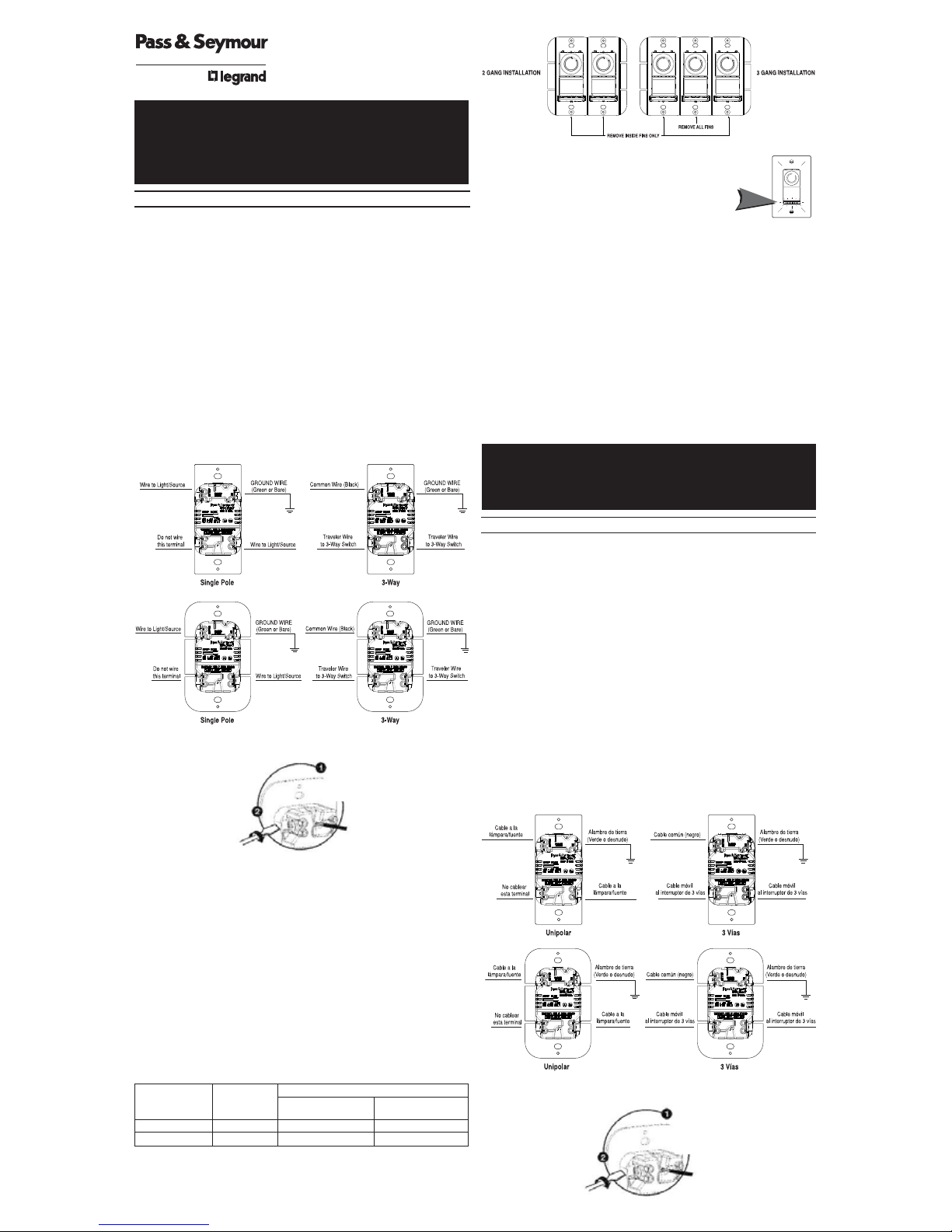
5. Connect dimmer as shown in the wiring and installation diagrams.
INSTALLATION DIAGRAMS FOR DIMMERS
6. Install dimmer in wall box, with word ‘TOP’ on metal strap right side up, using
mounting screws provided.
7. Attach wall plate.
8. Restore power and follow operating instructions.
Note: Protect from dirt and dust. The dimmer can be damaged from contaminates
encountered during the construction process. If lighting is required prior to the construction
process completion, then a switch should be temporarily installed in place of the dimmer.
The dimmer should not be installed until the construction process is complete.
OPERATING INSTRUCTIONS:
1. Toggle the switch provided to turn the dimmer ON and OFF.
2. Tochange lighting level rotate the knob clockwise or counterclockwise until desired
level is reached.
NOTE: Only a three way switch can be used to operate the light from a second location.
Control may feel warm to the touch in normal operation. This control is intended for
installation in a U.L. Listed metal or (polymeric) plastic outlet box.
MULTIPLE GANGING OF DIMMERS & OTHER DEVICES
Any combination of dimmer models and other devices may be ganged together. Break
off tabs are provided on the 1100W dimmer straps for multi-gang applications. Pry off
the tabs using pliers before installation, as shown in the multi-gang illustration. De-rate
the maximum load according to the following table:
Light Module: (sold separately, Catalog # TM8LMCC)
Transform in minutes a standard dimmer into an illuminated dimmer (ON
when light is OFF) – allows the dimmer to be found in the dark.
Average 20-year life expectancy.
No wiring – quick snap-in installation.
Any dimmer damage due to improper installation is not covered under warranty.
LIFETIME WARRANTY
The device you have purchased is warranted under normal use against defects in workmanship and
materials for as long as you own the device. If the device fails due to manufacturing defect during
normal use, return the device for replacement to the store where purchased or send to: Pass &
Seymour Legrand, 50 Boyd Avenue, Syracuse, NY 13209. All requests for replacement must include a
dated sales receipt (legible copies acceptable). ALL OTHER WARRANTIES, INCLUDING BUT NOT
LIMITED TO ANY WARRANTIES OF MERCHANTABILITY OR FITNESS FOR A PARTICULAR PURPOSE,
ARE LIMITED TO A PERIOD OF TWO YEARS FROM THE DATE OF PURCHASE. YOUR SOLE AND
EXCLUSIVE REMEDY AGAINST PASS & SEYMOUR LEGRAND UNDER ANY WARRANTY SHALL BE THE
EQUIVA L ENT REPLACEMENT OF THE DEVICE. IN NO EVENT SHALL ANY WARRANTY APPLY TO ANY
DEFECT ARISING OUT OF ANY ALTERATION OF THE DEVICE, IMPROPER WIRING, IMPROPER
INSTALLATION,MISUSE, ABNORMAL USE OR NEGLIGENCE. IN NO EVENT SHALL PASS & SEYMOUR
LEGRAND BE LIABLE FOR LOST PROFITS, INDIRECT, SPECIAL, EXEMPLARY, INCIDENTAL OR
CONSEQUENTIAL DAMAGES. Some states do not allow limitations on how long implied warranties
last and do not allow exclusion or limitation of incidental or consequential damages. Some of the
above limitations or exclusions may not apply to every purchaser .
INSTRUCCIONES EN ESPAÑOL
LEA Y GUARDE ESTAS INSTRUCCIONES
Para ser instalado por electricista certificado u otra persona capacitada.
ADVERTENCIA: Para prevenir una sacudida eléctrica severa o electrocución, siempre
C
ORTE la electricidad en el panel de servicio antes de instalar esta unidad, trabajar en
el circuito, o cambiar una lámpara.
AVISO: Para evitar el recalentamiento y los posibles daños a otro equipo, no instale este
dispositivo para controlar un tomacorriente, una lámpara o tubo fluorescente, un electrodoméstico a motor o un electrodoméstico alimentado por un transformador.
No use el reductor de luz con lámparas incandescentes cuyas requisitos de potencia
exija la potencia máxima (indicada en Wats) del reductor de luz.
No conecte al reductor de luz a otra fuente de potencia que no sea solo 120VAC, 60Hz.
Una carga mínima de 50W es requerida.
Solo utilice cables de cobre.
INSTRUCCIONES:
1. Desconecte la corriente del circuito quitando el fusible o APAGANDO los disyuntores
antes de instalar .
2. Quite la placa existente y los tornillos de la pared y quite el interruptor.
3. Desconecte del circuito el interruptor existente. Instalación de 3 vías: Identifique el
alambre “Común” (alambre conectado a la terminal marcado ‘common/común’ o al
terminal de color distinto). Para instalación “nueva”, identifique el alambre
conectado al suministro eléctrico o a la carga.
4. Peleelalambreutilizandolaguíaenlapartetraseradelaparato.
5. Conecte el reductor de luz como mostrado en el diagrama de instalación y alambrado.
DIAGRAMA DE INSTALACION
NEW
INSTALLATION INSTRUCTIONS
TradeMaster
®
DECORATOR ROTARY DIMMER
P/N 34087500
INSTRUCCIONES DE INSTALACÓN
TradeMaster
®
ATENUADOR GIRATORIO DECORATIVO
Screw Pressure Plate Back Wire
Securely tighten
screw beneath
wire hole to retain
inserted wire.
Insert wire
to bottom
of hole.
Termination takes
#12 or #14 AWG
stranded or solid,
copper conductors.
MULTI-GANGDE-RATING
DIMMER MAXIMUM
2GANG 3GANG
CATALOG # LOAD
INSTALLATION INSTALLATION
DR1103-P_V 1100W 900W 800W
DR703-P_V 700W 700W 700W
AtornilleelAlambreTraserodelaTapaPresora
Apriete el tornillo
debajo del hueco del
alambre para aguantar
el alambre insertado.
Introduzca el alambre al
hueco del fondo.
La terminación acepta
conductores trenzados
o sólidos #12 o #14 AWG
de cobre.

6. Instale el reductor de luz en la caja de pared con la palabra “TOP” en la correa de
metal hacia arriba, utilizando los tornillos de montaje proveídos.
7. Ponga la placa de pared.
8. Restáure el suministro eléctrico y siga las instrucciones de operación.
Nota: Proteja contra la suciedad y el polvo. El atenuador puede dañarse por contaminantes que se generan durante el proceso de construcción. Si se requiere iluminación
antes de la terminación de la construcción, entonces deberá instalarse provisionalmente
un interruptor en lugar del atenuador. El atenuador no debe instalarse antes de terminar
la construcción.
INSTRUCCIONES DE OPERACIÓN:
1. Mueva la báscula del interruptor suministrado para ENCENDER o APAGAR el
atenuador.
2. Para cambiar el nivel de luz, gire el botón a la derecha o izquierda, hasta que alcance
el nivel deseado.
NOTA: Solo un interruptor Tridireccional puede ser utilizado para operar la luz desde
otro sitio. El control podrá aparecer caliente al tacto durante su operación norma. Este
control está destinado para instalación en una caja plástica (polímera) o metálica
U.L. Listed.
AGRUPACIONES MÚLTIPLES DE REDUCTORES DE LUZ Y OTROS APARATOS
Cualquier combinación de modelos de reductores de luz u otros aparatos pueden ser
agrupados. Antes de la instalación, desprenda las lengüetas utilizando pinzas, tal como
se muestra en la figura para instalaciones en grupo de mútilples unidades. Reduzca la
capacidad máxima de acuerdo con la siguiente:
MÓDULO LUMINOSO: (vendido separado, N° de catálogo TM8LMCC)
Transforme en minutos un interruptor combinado estándar en un
interruptor iluminado (ENCENDIDO cuando la luz está APAGADA) –
p
ermite encontrar el interruptor en la oscuridad.
20 años de expectativa de vida promedio.
Instalación con inserción rápida – no requiere cableado.
Cualquier daño del atenuador causado por una instalación incorrecta no está amparado
por la garantía.
GARANTÍAS DE POR VIDA
El dispositivo que compró está garantizado bajo uso normal contra defectos de mano de obra y de
materiales mientras usted posea el dispositivo. Si el dispositivo falla debido a un defecto de
fabricación durante el uso normal, devuélvalo para su reemplazo a la tienda donde lo compró o
envíelo a: Pass & Seymour Legrand, 50 Boyd Avenue, Syracuse, NY 13209. Todas las solicitudes de
reemplazo deben incluir un recibo de compra con fecha (se aceptan copias legibles). CUALQUIER OTRA
GARANTÍA, INCLUYENDO PERO SIN LIMITARSE A CUALQUIER GARANTÍA DE APTITUD E IDONEIDAD
PARA UN FIN CONCRETO, ESTÁ LIMITADAA UN PERÍODO DE DOS AÑOS A PARTIR DE LA FECHA DE
COMPRA. SU RECURSO ÚNICO Y EXCLUSIVO EN CONTRA DE PASS & SEYMOUR/LEGRAND BAJO
CUALQUIER GARANTÍA SERÁ EL REEMPLAZO DEL DISPOSITIVO POR UNO EQUIVALENTE. EN
NINGÚN CASO SE APLICARÁ NGARANTÍA ALGUNA A UN DEFECTO DERIVADO DE UNA ALTERACIÓN
DEL DISPOSITIVO, CABLEADO INCORR ECTO, INSTALACIÓN INCORRECTA, USO INADECUADO, USO
ANORMAL O NEGLIGENCIA. PASS & SEYMOUR/LEGR AND NO SERÁ LEGALMENTE RESPONSABLE EN
NINGÚN CASO POR LA PÉRDIDA DE INGRESOS, DAÑOS Y PERJUICIOS INDIRECTOS, ESPECIALES,
EJEMPLAR E S, INCIDENTALES O CONSECUENTES. Algunos estados no permiten limitaciones en
cuanto a la duración de las garantías implícitas y no permiten la exclusión o limitación de los daños
incidentales o consecuentes. Algunas de las limitaciones o exclusiones anteriores podrían no
corresponder a todos los compradores.
INSTRUCTIONS EN FRANÇAIS
LIRE ET CONSERVER CES INSTRUCTIONS
Doit être installé par un électricien certifié ou une autre personne qualifiée.
ATTENTION – Pour éviter tout choc électrique ou une électrocution, toujours couper
l'électricité au niveau du panneau d'alimentation avant d’installer cette unité, de
travailler sur le circuit électrique ou de changer une lampe.
MISE EN GARDE - Pour éviter toute surchauffe et endommagement éventuel des autres
appareils, ne pas utiliser pour contrôler une prise, une lampe ou un tube fluorescent, ou
un appareil ménager équipé d’un moteur ou alimenté par un transformateur.
Ne pas utiliser ce gradateur avec des lampes à incandescence d’une puissance
supérieure à la puissance maximale (exprimée en watts) de ce gradateur.
Ne pas connecter ce gradateur à une source de courant autre que 120 VCA, 60 Hz.
Doit alimenter une charge de 50 W minimum.
N’utiliser que des fils en cuivre.
MODE D'EMPLOI
1.Couper l’alimentation du circuit en retirant le fusible ou en ouvrant les disjoncteurs
avant de commencer l’installation.
2.Retirer la plaque murale existante et les vis de fixation de l’interrupteur.
3.Déconnecter l’interrupteur existant du circuit. Installation 3 voies : Identifier le fil
commun (le fil connecté à la borne marquée "Common/ Commun" ou de couleur
particulière). Pour les nouvelles installations, identifier le fil connecté à la source de
courant ou à la charge.
4.Dénuder les fils en utilisant le gabarit reproduit au dos de l’unité.
5.Connecter le gradateur comme illustre sur les diagrammes de câblage et
d'installation.
DIAGRAMMES D'INSTALLATION POUR LES GRADATEURS
6.Installer le gradateur dans la boîte murale, avec le mot « TOP » en haut, en utilisant
les vis fournies.
7.Fixer la plaque murale.
8.Rétablir l’alimentation électrique et suivre les instructions d’utilisation.
Remarque : Protéger le dispositif de la saleté et de la poussière. Le gradateur peut être
endommagé par des débris laissés au cours de la construction. S'il est nécessaire
d’avoir une source d’éclairage avant la fin de la construction, installer provisoirement
un interrupteur à la place du gradateur. Le gradateur ne doit pas être installé avant la
findelaconstruction.
INSTRUCTIONS D’UTILISATION
1.Basculer l’interrupteur fourni pour ALLUMER ou ÉTEINDRE le gradateur.
2.Pour modifier l'intensité lumineuse, tourner le bouton d'un sens ou de l'autre jusqu'au
niveau désiré.
REMARQUE : N'utiliser qu'un interrupteur à 3 voies pour contrôler la lampe d'un
deuxième endroit. Le régulateur peut être tiède au toucher en fonctionnement
normal. Ce régulateur est conçu pour être installé dans une boîte électrique en métal
ou en plastique (polymère) homologuée par UL.
GROUPEMENT DE MULTIPLES GRADATEURS ET AUTRES DISPOSITIFS
N’importe quelle combinaison de gradateurs et d’autres dispositifs peuvent être
i
nstallés ensemble. Des languettes détachables sont prévues sur les bandes des
gradateurs de 1100 W pour les installations impliquant plusieurs unités. Détacher les
languettes avec une paire de pinces avant l’installation, comme illustré sur la figure
pour groupements. Réduire la puissance maximale conformément au tableau suivant:
MODULE LUMINEUX (VENDU SÉPARÉMENT, N° DE CATALOGUE TM8LMCC)
Permet de transformer en quelques minutes un gradateur standard en un
gradateur lumineux (ALLUMÉ lorsque la lumière est ÉTEINTE) – Permet de
trouver le gradateur dans le noir.
Durée de vie moyenne : 20 ans
Pas de câblage – Installation rapide par enfichage.
Aucun gradateur endommagé par une installation incorrecte n’est couvert par la garantie.
GARANTIE À VIE
Tantque vous en serez propriétaire et moyennant un usage normal, l’appar eilque vous avez acheté est garanti
contre tout défaut de fabrication et de matériaux. Si l’appareil ne fonctionne plus en raison d’un défaut de
fabrication alors qu’il en a été fait un usage normal, adressez-vous au magasin où vous l’avez acheté pour le
faire remplacer, ou expédiez-le à : Pass & Seymour Legrand, 50 Boyd Avenue, Syracuse, NY 13209. Toutes les
demandes de remplacement doivent s’accompagnerdu reçude caisse daté (les copies lisibles sont acceptées).
TOUTES LES AUTRES GARANTIES, Y COMPRIS, SANS S’Y LIMITER TOUTEFOIS, LES GARANTIES DE QUALITÉ
MARCHANDE OU D’ADAPTA TIONÀ UN USAGE PARTICULIER,SONT LIMITÉES À UNE PÉRIODE DEDEUX ANS
À COMPTER DE LA DATED’ACHAT. VOTRE SEUL ET UNIQUE RECOURS CONTRE PASS& SEYMOUR/LEGRAND
EN VERTU DE L’UNE OU L’AUTRE DES GARANTIES EST D’OBTENIR LE REMPLACEMENT ÉQUIVALENT DE
L ’APPAREIL. AUCUNE GARANTIE NE PEUT S’APPLIQUER EN AUCUN CAS CONTRE UN DÉFAUT DÛ À UNE
MODIFICATION DE L’ APP AREIL, À UN CÂBLAGE INCORRECT, À UNE MAUVAISE INSTALLATION, À UN
MAUVAIS USAGE, À UN USAGE ANORMAL OU À DE LA NÉGLIGENCE. PASS & SEYMOUR/LEGRAND NE PEUT
EN AUCUN CAS ÊTRE TENU RESPONSABLE DE PERTE DE PROFITS, DE DOMMAGES INDIRECTS, DE
DOMMAGES-INTÉRÊTS EXEMPLAIRES OU PARTICULIERS, DE DOMMAGES ACCESSOIRES OU DE
DOMMAGES CONSÉCUTIFS. Certains états et provinces n'autorisent pas la limitation de la durée des garanties
implicites et n’autorisent pas l'exclusion ou la limitation des dommages accessoires ou indirects. Certaines
limitations ou exclusions énumérées peuvent ne pas s’appliquer à tous les acheteurs.
REDUCCIÓN DE LA CAPACIDAD
NOMINAL EN CASO DE APLICACIONES
DE VARIAS UNIDADES
Nº DE CAPACIDAD
CONFIGURACIÓN CONFIGURACIÓN
CATÁLOGO MÁXIMA
DOBLE TRIPLE
DR1103-P_V 1100W 900W 800W
DR703-P_V 700W 700W 700W
RÉDUCTION DE PUISSANCE EN CAS DE
GROUPEMENT DE PLUSIEURS UNITÉS
Nº DE CATALOGUE CHARGE
CONFIGURATION CONFIGURATION
DU GRADATEUR MAXIMALE
DOUBLE TRIPLE
DR1103-P_V 1100W 900W 800W
DR703-P_V 700W 700W 700W
NEW
CONFIGURATION DOUBLE CONFIGURATION TRIPLE
RETIRER LES AILETTES
INTÉRIEURES UNIQUEMENT
RETIRER TOUTESLES AILETTES
NEW
INSTRUCTIONS D'INSTALLATION
TradeMaster
®
GRADATEUR ROTATIF DÉCORATEUR
Fil arrière avec vis et plaque de pression
Serrez bien la vis
située en dessous
du trou pour
i
mmobiliser
le fil inséré.
Insérezlefil
jusqu’au fond
du trou.
Utiliser des conducteurs
en cuivre massifs ou
torsadés de calibre
12 ou 14 AWG.
©2008 Pass & Seymour/Legrand Part No. 340875
P.O.Box 4822, Syracuse, NY 13221 www.passandseymour.com (800) 223-4185
 Loading...