

pass
TM
Feb. 4, 2010
XP-25 Owner’s Manual
XP-25 Owner’s Manual
1

INTRODUCTION:
Pass Laboratories, specifically Nelson Pass and his co-designer
Wayne Colburn have a long history of imagining and successfully
bringing to the discriminating consumer some of the finest phono
stage pre-amplifiers ever offered. Each new incarnation of the
Pass Laboratories phono preamps has pushed their personal limits
as to what level of acoustic bliss is realistically achievable from
“Streaming Analog”©.
Since 1997 the guiding credo for these phono pre-amps remains the
vision that music must flow effortlessly from LP surface to listeners
ear. With each evolution of product that effortless flow should
issue forth with greater detail and clarity while never forgetting or
sacrificing the soul of the music and the artistic intent. The Pass
Laboratories XP-25 does not disappoint.
The XP-25 was brought to market both by copious measurements
and extensive listening through a multitude of tone arm and
cartridge combinations. Listening was given precedent over the
numbers but never at the expense of measured performance. The
result is a dynamic, lush and smooth sound with dramatic detail and
spectacular layering. Those listeners familiar with Pass Laboratories
previous phono pre-amps will be struck by the clear delineation
of bass notes in the XP-25 and the greater sense of music in a real
physical space.
Like some great musicians we get requests! You spoke and we
listened… so that you can listen better. Now the XP-25 a product
designed at the intersections of excellence, adaptability and
convenience.
The twin chassis XP-25 eclipses the already exceptional performance
of the well-reviewed and well-received XP-15: delivering enhanced
RIAA performance at a fraction of the previous distortion. With
the XP-25 you are going to discover a whole new dimension of
dynamics, inner detail and spectral richness on your favorite LP’s.
The XP-25 brings all control and cartridge loading functions to
the front panel and presents them in a clear easy to understand
layout. The XP-25 boasts two separate and selectable inputs, ample
adjustable gain along with generous resistive and capacitive loading
choices.
Those listeners and archivists with the desire or need to sample
music from two tone-arms or turntables will be able to do so
instantly with a single XP-25, thus simplifying their complement
of analog equipment and removing one more variable from their
listening chain.
XP-25 Owner’s Manual
2

The addition of a user selectable high pass (low cut) filter makes
possible the playing of recordings with excessive subsonic
information.
The addition of a user selectable mute control makes possible the
cuing of records and needle drop in absolute silence.
The XP-25 is an uncommonly fine match with very low output
moving coil cartridges which would normally require a transformer
first stage.
By the early 1980’s it was generally acknowledged that lower output
moving coil cartridges were capable of retrieving significantly more
fine detail from record grooves than higher output moving magnet
cartridges. In many instances this was simply a case of having lower
moving mass to accelerate in the electrical generator mechanism of
the phono-cartridge. Moving coils with 3 or 4 turns of the finest
wire attached to the lightest and stiffest cantilevers were capable of
accurately tracking complex musical passages that a few years prior
would have seemed impossible tasks to engineer and listener alike.
The really astute cartridge makers had clearly taken a page from the
automotive and motorcycle racing cognoscenti, whose engineers who
were doing everything in their power to lower “un-sprung mass”
in an effort to get tires to say in intimate contact with the roughest
terrain at the highest possible speeds. In both worlds the ability to
accurately track the impossible landscape is the ultimate goal…..
minimal moving mass associated with a compliant suspension is a big
part of the answer.
Unfortunately the active electronics that were capable of extracting
signal at those low levels, frequently then buried much of that signal
in their own noise floor. Step-up transformers generally addressed
the noise issues, but frequently lost the very fine detail somewhere
in the transformers iron core. For the time, the promise of the best
moving coil cartridges went un-realized
The XP-25’s high gain and exceptionally low noise figure allow for
ample output and detail from cartridges providing as little as 40 uV
(micro-volts) of signal at the phono input.
The adjustable gain options of the XP-25 make this unit immune
from overload with any high output cartridge of which we are
familiar.
XP-25 Owner’s Manual
The XP-25 is as much a pleasure to use as it is to listen through,
thank you for trusting your ears and your vinyl collection with us.
3

Before you sit back and listen, take time to read and understand
cartridge loading. When you find the desired setting, please record
that setting so that you can come back to it in the future. For your
convenience we left space at the end of this manual for just these
sorts of details.
TECHNICAL DETAILS:
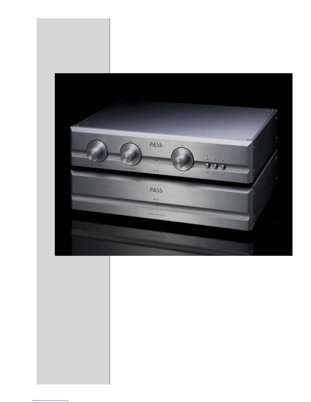
As previously indicated the XP-25 is a twin chassis design. One
chassis holds the fully filtered and regulated power supplies and
the second chassis houses the analog gain circuits, input switching,
loading and all those details and features normally associated with a
reference RIAA phono stage.
The two chassis are interconnected with a shielded and filtered Din25 cable. This Din-25 cable only carries power, never analog signal.
As far as this product is concerned you may use either Din-25 power
connector on the power supply chassis to link-up with the XP-25
control module. Both power connectors are identical and provide
identical performance from the phono-stage. The second Din-25
connector is capable of powering either another XP-25 phono-stage
or a Pass Laboratories XP-20 pre-amplifier without degradation of
measured or perceived performance.
Consumers frequently ask us if they may substitute a Din-25 cable
of their choice for the one Pass Laboratories supplies. The answer is
yes, provided that cable carries all the necessary legal approvals. For
those of you so inclined, please pick a shielded and filtered cable so
as to not degrade the full measure of performance your new XP25 is
capable of producing.
Never attach or detach the Din_25 cable with the power supply,
powered up from the wall. Always unplug your XP-25 from line
voltage prior to attaching or removing the Din 25 cable.
The rear of the power supply chassis has a standard IEC 320 power
inlet module a fuse holder and twin Din-25 power connectors. As
with the Din-25 cable, the user is free to substitute a suitable IEC
power cord of their choice. This product accepts any cordset with
an IEC 60320 C13 connector or equivalent. Be aware however that
the XP-25 power supply is not particularly sensitive to differences in
properly terminated power cords.
If you substitute an aftermarket power cord you need to be aware
of the following. The ground pin on the power cord provides this
XP-25 Owner’s Manual
4

product’s safety ground, for your safety and the integrity of this
product the safety ground must never be defeated. Additionally this
product has filter components in the AC line that are designed to
shunt unwanted noise from the power-line to ground. Defeating
the safety ground will ultimately defeat some of the performance
advantages built into this product.
To insure maximum performance and maximum safety use only
power cords that are grounded and carry all the necessary approvals
and directives from the local regulating authorities.
Lets talk about AC power requirements. Your new XP-25 is built
voltage specific to your market. Line voltage is determined at the
time of construction and is not changeable. The products voltage
and current requirements will be indicated on a tag affixed to the rear
panel of the XP-25’s power supply chassis. This tag will indicate a
nominal 100 volts, 120 volts, 220 volts, or 240 volts with allowances
for normal variations of the nominal indicated build voltage.
The AC Line Voltage in all instances will be 50 - 60 Hz. Please verify
that that voltage indicated on the product is consistent with the
nominal voltage supplied at your location.
All XP25 products are protected by a voltage specific type 3AG
fuse (1/4” x 1-1/4”). For 100 Volts ac and 120 Volts ac the fuse
will be 1 amp, for 220 Volts ac and 240 Volts ac the fuse will be
amp. In all instances the fuse will have a slow blow time constant.
Substitution of another time constant other than “slow blow” at
the same amperage will not harm this product, but we would not
expect longevity from the fuse element. It is not suggested that
you substitute any other fuse type or fuse rating, deviation from the
indicated physical size of fuse (1/4” x 1-1/4”) may cause significant
physical damage to the fuse holder and put the product and your
safety at risk.
ADJUSTMENT:
In order to set the XP-25 in a way which optimizes the performance
of your phono-cartridge it will be helpful though not absolutely
necessary that you have some information and set up suggestions
on that specific cartridge. If you do not have data on the cartridge
and do not wish to re-invent the wheel, contact the dealer or the Pass
Laboratories factory. We will attempt to help you with that data, but
by no means do we have data for every cartridge arm combination
ever built.
XP-25 Owner’s Manual
At the bare minimum you should know and have set the suggested
5

optimal tracking force for the cartridge and have already set the
overhang and vta as per the tonearm makers instructions, anti-skate
and azimuth if possible.
The usual procedure is to select input jacks on phono pre-amps
based on cartridge type, Moving Magnet or Moving Coil. As
previously indicated the XP-25 is not typical and is designed
to simplify your life. With the XP-25 cartridge types will be
accommodated by gain and loading selections from the XP-25 front
panel.
In general MM (moving magnet) cartridges will require a gain setting
of 53 dB, MC (moving coil) a setting of 66dB or 76dB. Moving
Iron cartridges, usually 66dB. However there are no fixed rules, the
requisite setting is that setting which works best in your situation.
Some listeners will select gain based on a sonic preference others
simply will choose a setting that brings their phono system output on
parity with their other source components. Either choice is equally
valid.
Moving magnet and moving iron cartridges typically work very
well with a series loading of 47k-ohms and 100 pf of parallel
capacitance. Like gain, these settings too are selectable from the
front panel of the XP25. Presuming 47k-ohm in the case of moving
magnet, greatest benefit comes from exploring the pallet of available
capacitive loading choices. Infrequently moving magnet cartridges
will perform best at other than 47k-ohm but that would be an
exception.
XP-25 Owner’s Manual
Moving Coil cartridges frequently do best with lower impedance
loads and see little advantage from additional capacitance. From the
front panel your choices of cartridge loading will be as follows:
Resistive loading choices; 30 ohm, 50 ohm, 100 ohm, 160 ohm, 250
ohm, 320 ohm, 500 ohm, 1k-ohm, 47k-ohm
Reactive loading choices; 100 pf, 200 pf, 320 pf, 430 pf, 530 pf and
750 pf.
If you have other than a moving coil cartridge, please take time to
read the short treatise on moving coil cartridges, the philosophy
and exercise of how one might go about adjusting for a particular
cartridge is not exclusive to the moving coil.
While the loading of moving magnet cartridges is rather straight
forward, the loading of moving coil cartridges is at best a very
inexact science. Specific requirements for loading moving coil
devices should be taken (and offered) very lightly.
6

The XP-25 is not typical and I encourage you to think separately
from the cartridge manufacturer and choose your resistive loadings
accordingly.
As for example with the very lowest output cartridges, the cartridge
maker likely anticipated a transformer being used as the initial
stage of gain, the XP-25 with its active elements is a very different
proposition from a transformer as seen by the cartridge. This
fundamental difference of circuit topology can affect loading
preferences.
As an added complexity; part of the cartridge loading is always
provided by the lead-in wiring. The XP-25 is sufficiently revealing
such that the resistance and reactance of that wire should be
accounted for in choosing loading values in the XP-25. As long as
you derive your final setting empirically through careful listening you
may ignore these wire effects; however your cartridge will not.
An improperly loaded cartridge will suffer every unwanted sonic
anomaly, ranging from lack of definition and bass to a very strident
and screechy high end.
Cartridge loading is a compromise between what works best for
the cartridge and what sounds best for the listener. Specifically in
selecting a cartridge load, we will be listening for a compromise
loading which sounds best across the whole audio spectrum and
specifically not that loading which optimizes one cut on one LP.
The front panel controls of the XP-25 load each channel of the
phono-cartridge independently through closely to preserve the best
possible spatial elements of recordings. The XP-25 is a dual mono
design, which minimizes cross talk between channels. The loading
resistors and capacitors are isolated from the front panel switches to
provide the best possible signal to noise figures possible.
I suggest you start with the following for moving coil cartridges:
Always, ALWAYS reduce the volume or mute the output of your
preamp before making any adjustments of the XP-25 cartridge
loading. Load and input changes made to the XP-25 have a small
but non-zero possibility of sending pulses to your pre-amplifier that
could damage loudspeakers provided the volume of the pre-amplifier
is set sufficiently high. Damage to your equipment is highly unlikely
but in light of the effort and expense your equipment represents we
believe that caution however un-necessary is warranted.
XP-25 Owner’s Manual
Start by selecting an initial resistive load of 100 ohms. Give the
XP-25 electronics a couple of minutes to settle in and listen to the
7

system critically for some time (10 minutes to 1 hour) using various
musical selections that you are familiar with.
Once again reduce the gain on your preamp and select the next
lowest resistive loading value (50 ohms) from the XP-25 front panel.
Once again give the electronics a couple minutes to settle in and
listen to the same musical selections as before. If your test selections
sound better with the new 50-ohm loading you can be assured
that the loading change was in the correct (lower resistance in this
example) direction.
If this second load selection resulted in an even more pleasant
presentation of your chosen musical selections, select the next lower
resistive value, 30 ohms, and listen to the same selections once again.
At some point you will find a value where the perceived sound
deteriorates, move back to the last value that sounded excellent.
Once this has been done, you have reached the apparent optimal
resistive loading.
If going below 100 ohms resulted in degraded sound, then obviously
the correct change would have been to have gone upward to 160
ohms, where you would repeat the listening test. I am sure you get
the idea, it is not complicated, but it can be time consuming.
Capacitive loading follows the same rigor and affects the finer
points of resistive loading. The final and optimal setting will require
alternating between resistive and reactive loading elements, peaking
each element in turn until no further gains are achieved.
Capacitive loading will not affect moving coil cartridges to the same
extent that capacitive loading affects moving magnet cartridges but
the effect may be worth considering and optimizing this parameter
once resistive loading is optimal.
Again I would like to stress that you are listening for a musical
balance in the selections that you play. Some loading selections will
offer better bass but suffer from poor high-end resolution, some
will have spectacular high-end definition but have a flat sound stage.
You are seeking an optimal condition with correct spectral balance
in conjunction with correct spatial information. The XP-25 equips
you with the tools for the task. Finding the best compromise will
however take time.
Do not make the mistake of setting the XP-25 such that it enhances
one recording only, listen to a variety of well-recorded material and
adjust accordingly. Avoid the folly of only auditioning and adjusting
to your favorite LP.
XP-25 Owner’s Manual
8

Once you have found the optimal settings, take the time to record
those settings, so that should the need ever arrive, you can replicate
your personal best settings quickly and with minimal effort. Of
course whenever your change cartridges or wiring between the
phono cartridge and XP-25 it would be wise to revisit your selected
settings and make the requisite addition to your notes. Space is
provided at the end of this manual to record those settings.
PRODUCT PHILOSPHY and DESIGN:
For a very long time there has been faith in the technical community
that eventually some objective analysis would reconcile critical
listeners subjective experience with a repeatable laboratory
measurement protocol. Perhaps this will ultimately occur, but in
the meantime audiophiles largely reject bench specifications as an
indicator of audio quality. This is appropriate; the appreciation of
audio is a completely subjective human experience. We should not
more let the numbers define audio quality than we would let chemical
analysis be the ultimate arbiter of fine wines. Measurements are
certainly critical, they can and do provide a measure of insight, but
are no substitute for human judgment of that which is pleasant.
As in art, classic audio components are the results of individual
and collective efforts that reflect a coherent underlying goal and
philosophy by the major participants. If successful, they make both a
subjective and objective statement of quality, which is meant to illicit
appreciation in the final product. It is essential that that the circuitry
of an audio component reflects a philosophy which addresses the
subjective nature of its performance first and foremost.
Lacking the ability to completely characterize performance in an
objective manner, we should take a step back from the resulting
waveform and take into account the process by which it has been
achieved. The history of what has been done to the music is
important and must be considered a part of the result. Everything
that has been done to the signal is embedded in that signal, however
subtly.
Experience correlating what sounds good to knowledge of
component design yields some general guidelines as to what will
sound good and what will not sound good in real life.
1) Simplicity and a minimum number of components is a key
element, and is well reflected in the quality of better tube
designs. The fewer pieces in series with the signal path, the better.
This is often true even if adding just one more gain stage will
XP-25 Owner’s Manual
9

improve the measured performance.
2) The characteristic of gain devices and their specific use is
important. Individual variations in performance between like
devices is important, as are differences in topological usage.
All signal bearing devices contribute to the degradation, but
there are some different characteristics that are worth
attention. Low order nonlinearities are largely additive in
quality, bringing false warmth and coloration, while abrupt high
order nonlinearities add harshness.
3) Maximum intrinsic linearity is desired. This is the
performance of the gain stages before feedback is applied.
Experience suggests that feedback is a subtractive process; it
removes information from the signal. In many older designs,
poor intrinsic linearity has been corrected out by large
application of feedback, resulting in loss of warmth, space
and detail.
We give these precepts a great deal of thought in the design and
voicing of product so that you do not have to. You only need to
address the cartridge loading till it sounds good to you. Once set you
can relax and focus on the results.
WARRANTY:
Please check with the factory authorized distributor in the country where
you are purchasing this product for specific warranty information.
All Pass Laboratories products purchased new from an authorized Pass
Laboratories dealer in North America are covered by a transferable, limited
3-year warranty. This warranty includes all parts and labor charges incurred
at the factory or factory specified repair facility, exclusive of any subsequent
or consequential damages. Damage due to physical abuse is specifically
excluded under this warranty.
For this warranty to apply the customer is responsible for returning the
product unmodified to the factory within the specified warranty period.
The customer assumes all responsibility for shipping and insurance to
and from the factory or a factory specified repair facility. The conditions
and stipulations of this Pass Laboratories warranty only applies to units
originally sold new through an authorized dealer. Warranty on factory
repair is 60 days and covers only the scope of the original repair.
Non-North America customers should consult with their original Pass Labs
dealer or distributor for warranty repair instruction prior to contacting the
factory or shipping product to the factory for repair.
XP-25 Owner’s Manual
10

Non-North American product must be returned to the country of origin
for warranty service. Foreign distributors are only required to offer
warranty service on Pass Laboratories product that they have imported,
verifiable by serial number.
Please note: Conditions of warranty service and customer rights for
product purchased outside the United States may vary depending upon
the distributor and local laws. Please check with your local distributor for
specific rights and details.
Any modifications to Pass Laboratories products that have not received
written factory approval nullify all claims and void all provisions of the
warranty and liability by the maker or authorized distributor. Should a
modified product be returned to the factory for repair the owner will be
required to pay all necessary charges for the repair in addition to those
charges required to return the product to it’s original configuration.
In the case of safety issues, no product shall be returned to the customer
without those safety issues being corrected to the most recent accepted
standards.
Removal or alteration of original Pass Labs serial numbers voids the factory
warranty. Product with altered or missing serial numbers will be suspect as
counterfeit or stolen product.
Pass Laboratories will not repair or in any way indemnify any counterfeit or
cloned product.
Pass Laboratories does not offer products in voltages intended for
international markets either to authorized Pass Labs dealers or to third
parties located in the United States or Canada.
For more information please contact: Pass Laboratories Inc.
© 2008 Pass Laboratories Inc..
XP-25 Owner’s Manual
11

SPECIFICATIONS:
Gain 53 dB (47 Single-ended)
66 dB (60 SE)
76 dB (70 SE)
RIAA response plus/minus .1 dB 20-20 KHz
Distortion < .005 % THD @ 1mV MC input
< .002 % THD @ 10mV MM input
Maximum Output 22 volts rms.
Output Impedance 150/150 ohms
Input Impedance 100pF - 750pF on any input
30 ohm - 47K ohm any input
Unweighted Noise -93 dB ref. 10 mV (MM)
-85 dB ref. 1 mV (MC)
Power consumption 25 watts
Dimensions, 2 @ 17”W x 12”D x 4”H
Shipping Weight 55 pounds in packing carton
XP-25 Owner’s Manual
“Pass”, “pass”, “Pass Labs”, “Pass Laboratories”, Supersymmetery”,
“Aleph”, and “Zen” and are all registered trademarks of Pass
Laboratories, Inc., and all rights thereto are protected by law.
12

For your protection please
read the following:
Water and moisture: Electrical devices should not be used near
water ( as per example, near a bathtub, washbasin, kitchen sink,
laundry tub, wet basement or swimming pool ). Care should be
taken such that objects do not have the opportunity to fall, and that
liquid is never spilled onto or into the device enclosure through
openings.
Power Sources: An electrical device must be connected to a mains
power source in strict accordance with the supplied product owner’s
manual. Please verify that the AC mains voltage specified in the
product manual matches those requirements indicated on the unit
and the AC voltage provided to your location by the power company.
Grounding: Adequate precautions should be taken so that the
grounding provisions built into an electrical product are never
defeated.
Power Cords: Pass Laboratories provides a power supply cord that
meets all legislated requirements for the market in which the product
was originally sold. If you choose to substitute an after-market
product we urge you to choose one that is fully safety rated by the
necessary local authority.
Power Cord Protection: Power supply cords should be routed so
that they are not likely to be walked on, abraded, or pinched by items
placed on or against them, paying particular attention to cords where
they enter plugs or exit from a device. Never under any circumstance
insert a cut or damaged power cord into a mains power socket.
Power and Signal: Cables should never be connected /
disconnected with equipment powered up. Failure to heed this
warning may damage or destroy equipment.
Ventilation: Power-amplifiers run hot, but you should be able to
place your hands on them without discomfort. You must allow for
this heat in installation, by providing for free air circulation around
the product. Electronics should not be subjected to sources of
excessive radiant heat. Excessive heat can shorten the life of the
product and may cause the electronics to self-protect and shut down.
Servicing: To reduce the risk of fire, electrical shock or other
injuries, the user should not attempt to service the device beyond
that which is described in the operating instructions. All other
servicing must be referred to qualified service personnel.
XP-25 Owner’s Manual
13

XP-25 Owner’s Manual
14
 Loading...