

Pass and Seymour d b a Legrand DA1104 User Manual

802.11ac Dual Band Ceiling Mount
Wireless Access Point
(P/N:DA1104)
Owner’s Manual
P/N 1308237 Rev. A

Federal Communications Commission Statement
This device complies with Part 15 of the FCC Rules and RSS-210 Issue 8 of Canada. Operation is
subject to the following two conditions:
This device may not cause harmful interference, and
This device must accept any interference received, including interference that may cause
undesired operation.
This equipment has been tested and found to comply with the limits for a class B digital device, pursuant
to Part 15 of the Federal Communications Commission (FCC) rules. These limits are designed to
provide reasonable protection against harmful interference in a residential installation. This equipment
generates, uses, and can radiate radio frequency energy and, if not installed and used in accordance
with the instructions, may cause harmful interference to radio communications. However, there is no
guarantee that interference will not occur in a particular installation. If this equipment does cause
harmful interference to radio or television reception, which can be determined by turning the equipment
off and on, the user is encouraged to try to correct the interference by
one or more of the following measures:
Reorient or relocate the receiving antenna.
Increase the separation between the equipment and receiver.
Connect the equipment into an outlet on a circuit different from that to which the receiver is
connected.
Consult the dealer or an experienced radio/TV technician for help.
Reprinted from the Code of Federal Regulations #47, part 15.193, 1993. Washington DC: Office of the
Federal Register, National Archives and Records Administration, U.S. Government Printing Office.
Canadian Department of Communications
This digital apparatus does not exceed the Class B limits for radio noise emissions from digital
apparatus set out in the Radio Interference Regulations of the Canadian Department of
Communications.
This Class B digital apparatus complies with Canadian ICES-003. Cet appareil numérique de la classe
B est conforme à la norme NMB-003 du Canada.
Le manuel d'utilisation des appareils radio exempts de licence doit contenir l'énoncé qui suit, ou
l'équivalent, à un endroit bien en vue et/ou sur les appareils :
Le présent appareil est conforme aux CNR d'Industrie Canada applicables aux appareils radio exempts
de licence. L'exploitation est autorisée aux deux conditions suivantes : (1) l'appareil ne doit pas produire
de brouillage, et (2) l'utilisateur de l'appareil doit accepter tout brouillage radioélectrique subi, même si
le brouillage est susceptible d'en compromettre le fonctionnement.
FCC Radio Frequency Exposure Caution Statement
In order to maintain compliance with the FCC RF exposure guidelines, this equipment should be
installed and operated with minimum distance 20cm between the radiator and your body. Use only with
supplied antenna. Unauthorized antenna, modification, or attachments could damage the transmitter
and may violate FCC regulations. Any changes of modifications not expressly approved by the grantee
of this device could void the users authority to operate the equipment. Installation and use of this
Wireless LAN device must be in strict accordance with the instructions included in the user
documentation provided with the product. Any changes or modifications (including the antennas) made
to this device that are not expressly approved by the manufacturer may void the user’s authority to
operate the equipment. The manufacturer is not responsible for any radio or television interference
caused by unauthorized modification of this device, or the substitution or attachment of connecting
I

cables and equipment other than manufacturer specified. It is the responsibility of the user to correct
any interference caused by such unauthorized modification, substitution or attachment. Manufacturer
and its authorized resellers or distributors will assume no liability for any damage or violation of
government regulations arising from failing to comply with these guidelines.
This device and its antenna(s) must not be co-located or operating in conjunction with any
other antenna or transmitter.
Declaration of Conformity (R&TTE directive 1999/5/EC)
The following items were completed and are considered relevant and sufficient:
Essential requirements as in [Article 3]
Protection requirements for health and safety as in [Article 3.1a]
Testing for electric safety according to [EN 60950]
Protection requirements for electromagnetic compatibility in [Article 3.1b]
Testing for electromagnetic compatibility in [EN 301 489-1] & [EN 301]
Testing according to [489-17]
Effective use of the radio spectrum as in [Article 3.2]
Testing for radio test suites according to [EN 300 328-2]
WARNING: TO PREVENT FIRE OR SHOCK HAZARD, DO NOT EXPOSE THIS PRODUCT TO
RAIN OR MOISTURE. THE UNIT MUST NOT BE EXPOSED TO DRIPPING OR SPLASHING
WATER.
CAUTION: DO NOT OPEN THE UNIT. DO NOT PERFORM ANY SERVICING OTHER THAN THAT
CONTAINED IN THE INSTALLATION AND TROUBLESHOOTING INSTRUCTIONS. REFER ALL
SERVICING TO QUALIFIED SERVICE PERSONNEL.
CAUTION: THIS DEVICE MUST BE INSTALLED AND USED IN STRICT ACCORDANCE WITH
THE MANUFACTURER’S INSTRUCTIONS AS DESCRIBED IN THE USER DOCUMENTATION
THAT COMES WITH THE PRODUCT.
WARNING: POSTPONE INSTALLATION UNTIL THERE IS NO RISK OF THUNDERSTORM OR
LIGHTNING ACTIVITY IN THE AREA.
When using this device, basic safety precautions should always be followed to reduce the risk of fire,
electric shock and injury to persons, including the following:
Read all of the instructions {listed here and/or in the user manual} before you operate this
equipment.
Give particular attention to all safety precautions.
Retain the instructions for future reference.
Comply with all warning and caution statements in the instructions.
Observe all warning and caution symbols that are affixed to this equipment.
Comply with all instructions that accompany this equipment.
Avoid using this product during an electrical storm. There may be a risk of electric shock from
lightning. For added protection for this product during a lightning storm, or when it is left
unattended and unused for long periods of time, unplug the power supply, and disconnect the Cat
5e to the DA1104 at the POE Inserter. This will prevent damage to the product due to lightning and
power surges. It is recommended that the customer install an AC surge protector in the AC outlet
to which this device is connected. This is to avoid damaging the equipment by local lightning
strikes and other electrical surges.
Operate this product only from the type of power source indicated on the product’s marking label.
II

If you are not sure of the type of power supplied to your home, consult your dealer or local power
company.
Upon completion of any service or repairs to this product, ask the service technician to perform
safety checks to determine that the product is in safe operating condition.
Installation of this product must be in accordance with national wiring codes and conform to local
regulations.
Place POE Inserter to allow for easy access when disconnecting the power cord/adapter of the device
from the AC wall outlet.
Wipe the unit with a clean, dry cloth. Never use cleaning fluid or similar chemicals. Do not spray
cleaners directly on the unit or use forced air to remove dust.
When not utilizing the recommended 3-gang plastic switch & outlet box, do not directly cover the device,
or block the airflow to the device with insulation or any other objects.
Keep the device away from excessive heat and humidity and keep the device free from vibration and
dust.
III

CONTENTS
Chapter 1. Product Introduction...........................................................................................................1
1.1 Package Contents ...............................................................................................................1
1.2 Product Description............................................................................................................2
1.3 Product Features.................................................................................................................3
1.4 Product Specifications .......................................................................................................4
Chapter 2. Hardware Installation ..........................................................................................................7
2.1 Product Installation Overview............................................................................................7
2.1.1 Panel Layout.............................................................................................................8
2.1.2 Hardware Description...............................................................................................9
Chapter 3. Connecting to the AP........................................................................................................10
3.1 System Requirements ......................................................................................................10
3.2 Web configuration access................................................................................................10
3.2.1 Configuring the IP Address Manually .....................................................................10
3.2.2 Starting Setup in the Web UI...................................... ... ... ... ... ... ... ... ... ... ... .... ... ... ....13
Chapter 4. Configuring the AP............................................................................................................15
4.1 Setup Wizard......................................................................................................................15
4.2 TCP / IP Settings................................................................................................................22
4.2.1 LAN Settings...........................................................................................................22
4.3 WLAN1 (5GHz)...................................................................................................................24
4.3.1 Basic Settings................................................................ ... ... ... ... ... ... ... ... ... ... .... ... ... .24
4.3.2 Advanced Settings.................................................................. ... ... ... ... ... ... ... .... ... ... .38
4.3.3 RF Output Power....................................................................................................39
4.3.4 Security...................................................................................................................40
4.3.5 Access Control........................................................................................................41
4.3.6 WDS........................................................................................................................43
4.3.7 Site Survey .............................................................................................................45
4.3.8 WPS........................................................................................................................46
4.3.9 Schedule.................................................................................................................49
4.4 WLAN2 (2.4GHz)................................................................................................................50
4.4.1 Basic Settings................................................................ ... ... ... ... ... ... ... ... ... ... .... ... ... .50
4.4.2 Advanced Settings.................................................................. ... ... ... ... ... ... ... .... ... ... .65
4.4.3 RF Output Power....................................................................................................67
4.4.4 Security...................................................................................................................67
4.4.5 Access Control........................................................................................................69
4.4.6 WDS........................................................................................................................71
4.4.7 Site Survey .............................................................................................................73
4.4.8 WPS........................................................................................................................73
IV

4.4.9 Schedule.................................................................................................................77
4.5 Management ......................................................................................................................77
4.5.1 Status......................................................................................................................78
4.5.2 Statistics..................................................................................................................79
4.5.3 SNMP......................................................................................................................80
4.5.4 NTP Settings...........................................................................................................81
4.5.5 Schedule Reboot....................................................................................................83
4.5.6 LOG ........................................................................................................................85
4.5.7 Upgrade Firmware......................................................... ... ... ... ... ... ... ... ... ... ... .... ... ... .86
4.5.8 Reload Settings .................................... ... ... ... ... ... .... ... ... ... ... ... ... ... ... ... ... ....... ... ... ... .86
4.5.9 Password................................................................................................................88
4.5.10 Logout.....................................................................................................................89
Chapter 5. Quick Connection to a Wireless Network .......................................................................90
5.1 Windows XP (Wireless Zero Configuration)...................................................................90
5.2 Windows 7 (WLAN AutoConfig).......................................................................................92
5.3 Mac OS X 10.x....................................................................................................................95
5.4 iPhone / iPod Touch / iPad ...............................................................................................99
Appendix A: Legrand Smart Discovery Utility ...............................................................................102
Appendix B: Troubleshooting..........................................................................................................103
Appendix C: Glossary.......................................................................................................................105
V

FIGURE
FIGURE 2-1 DA1104 PRODUCT INSTALLATION DRAWING.......................................................................................7
FIGURE 2-2 DA1104 PANEL LAYOUT - LED...........................................................................................................8
FIGURE 2-3 DA1104 PANEL LAYOUT – RESET BUTTON..........................................................................................8
FIGURE 3-1 TCP/IP SETTING................................................................................................................................11
FIGURE 3-2 WINDOWS START MENU ....................................................................................................................12
FIGURE 3-3 SUCCESSFUL RESULT OF PING COMMAND .......................................................................................... 12
FIGURE 3-4 FAILED RESULT OF PING COMMAND..................................................................................................13
FIGURE 3-5 LOGIN BY DEFAU LT IP ADDRESS.........................................................................................................13
FIGURE 3-6 LOGIN WINDOW ................................................................................................................................14
FIGURE 4-1 MAIN MENU ...................................................................................................................................... 15
FIGURE 4-2 SETUP WIZARD.................................................................................................................................. 15
FIGURE 4-3 WIZARD – LAN INTERFACE SETUP....................................................................................................16
FIGURE 4-4 WIZARD – TIME ZONE SETUP ............................................................................................................16
FIGURE 4-5 WIZARD – WIRELESS 5GHZ BASIC SETTINGS....................................................................................17
FIGURE 4-6 WIZARD – WIRELESS 5GHZ SECURITY SETUP ...................................................................................18
FIGURE 4-7 5GHZ WIRELESS SECURITY SETUP – WEP SETTING ..........................................................................18
FIGURE 4-8 5GHZ WIRELESS SECURITY SETUP – WPA SETTING..........................................................................19
FIGURE 4-9 WIZARD – WIRELESS 2.4GHZ BASIC SETTINGS.................................................................................19
FIGURE 4-10 WIZARD – WIRELESS 2.4GHZ SECURITY SETUP..............................................................................20
FIGURE 4-11 2.4GHZ WIRELESS SECURITY SETUP – WEP SETTING..................................................................... 20
FIGURE 4-12 2.4GHZ WIRELESS SECURITY SETUP – WPA SETTING..................................................................... 21
FIGURE 4-13 SETUP WIZARD - FINISHED.............................................................................................................. 21
FIGURE 4-14 LAN SETTING..................................................................................................................................22
FIGURE 4-15 5GHZ WIRELESS MAIN MENU.........................................................................................................24
FIGURE 4-16 5GHZ WIRELESS BASIC SETTINGS OF AP........................................................................................25
FIGURE 4-17 5GHZ WIRELESS BASIC SETTINGS – MULTIPLE AP ......................................................................... 27
FIGURE 4-18 5GHZ MULTIPLE-SSID....................................................................................................................27
FIGURE 4-19 5GHZ UNIVERSAL REPEATER-1.......................................................................................................28
FIGURE 4-20 5GHZ UNIVERSAL REPEATER-2.......................................................................................................29
FIGURE 4-21 5GHZ UNIVERSAL REPEATER-3.......................................................................................................29
FIGURE 4-22 5GHZ UNIVERSAL REPEATER-4.......................................................................................................29
FIGURE 4-23 5GHZ UNIVERSAL REPEATER-5.......................................................................................................30
FIGURE 4-24 5GHZ WIRELESS BASIC SETTINGS – CLIENT ...................................................................................30
FIGURE 4-25 CLIENT – AP LIST............................................................................................................................ 32
FIGURE 4-26 CLIENT – SECURITY.........................................................................................................................33
FIGURE 4-27 CLIENT – STATUS ............................................................................................................................. 33
FIGURE 4-28 5GHZ WIRELESS BASIC SETTINGS – WDS ......................................................................................34
FIGURE 4-29 5GHZ WIRELESS BASIC SETTINGS – WDS+AP...............................................................................36
FIGURE 4-30 WIRELESS ADVANCED SETTINGS – 5GHZ........................................................................................38
FIGURE 4-31 RF OUTPUT POWER – 5GHZ ............................................................................................................39
FIGURE 4-32 WIRELESS SECURITY SETTINGS – 5GHZ..........................................................................................40
FIGURE 4-33 WIRELESS ACCESS CONTROL – 5GHZ .............................................................................................41
VI

FIGURE 4-34 WIRELESS ACCESS CONTROL – DENY..............................................................................................42
FIGURE 4-35 WDS MODE – 5GHZ .......................................................................................................................43
FIGURE 4-36 WDS SETTINGS – 5GHZ ..................................................................................................................44
FIGURE 4-37 WDS – SET SECURITY ..................................................................................................................... 44
FIGURE 4-38 SITE SURVEY – 5GHZ ......................................................................................................................45
FIGURE 4-39 WPS-PBC – 5GHZ-1....................................................................................................................... 47
FIGURE 4-40 WPS-PBC – 5GHZ-2....................................................................................................................... 47
FIGURE 4-41 WPS-PIN – 5GHZ-1........................................................................................................................ 48
FIGURE 4-42 WPS-PIN – 5GHZ-2........................................................................................................................ 48
FIGURE 4-43 WPS-PIN – 5GHZ-3........................................................................................................................ 48
FIGURE 4-44 SCHEDULE - 5GHZ...........................................................................................................................49
FIGURE 4-45 2.4GHZ WIRELESS MAIN MENU......................................................................................................50
FIGURE 4-46 2.4GHZ WIRELESS BASIC SETTINGS – AP.......................................................................................51
FIGURE 4-47 2.4GHZ WIRELESS BASIC SETTINGS – MULTIPLE AP ...................................................................... 53
FIGURE 4-48 2.4GHZ MULTIPLE-SSID................................................................................................................. 53
FIGURE 4-49 2.4GHZ UNIVERSAL REPEATER-1....................................................................................................54
FIGURE 4-50 2.4GHZ UNIVERSAL REPEATER-2....................................................................................................55
FIGURE 4-51 2.4GHZ UNIVERSAL REPEATER-3....................................................................................................55
FIGURE 4-52 2.4GHZ UNIVERSAL REPEATER-4....................................................................................................56
FIGURE 4-53 2.4GHZ UNIVERSAL REPEATER-5....................................................................................................56
FIGURE 4-54 2.4GHZ WIRELESS BASIC SETTINGS – CLIENT ................................................................................57
FIGURE 4-55 CLIENT – AP LIST............................................................................................................................ 59
FIGURE 4-56 CLIENT – SECURITY.........................................................................................................................60
FIGURE 4-57 CLIENT – STATUS ............................................................................................................................. 60
FIGURE 4-58 2.4GHZ WIRELESS BASIC SETTINGS – WDS ...................................................................................61
FIGURE 4-59 2.4GHZ WIRELESS BASIC SETTINGS – WDS+AP............................................................................63
FIGURE 4-60 WIRELESS ADVANCED SETTINGS – 2.4GHZ.....................................................................................65
FIGURE 4-61 RF OUTPUT POWER – 2.4GHZ......................................................................................................... 67
FIGURE 4-62 WIRELESS SECURITY SETTINGS – 2.4GHZ.......................................................................................67
FIGURE 4-63 WIRELESS ACCESS CONTROL – 2.4GHZ .......................................................................................... 69
FIGURE 4-64 WIRELESS ACCESS CONTROL – DENY..............................................................................................70
FIGURE 4-65 WDS MODE – 2.4GHZ ....................................................................................................................71
FIGURE 4-66 WDS SETTINGS – 2.4GHZ............................................................................................................... 71
FIGURE 4-67 WDS – SET SECURITY ..................................................................................................................... 72
FIGURE 4-68 SITE SURVEY – 2.4GHZ ................................................................................................................... 73
FIGURE 4-69 WPS-PBC – 2.4GHZ-1.................................................................................................................... 75
FIGURE 4-70 WPS-PBC – 2.4GHZ-2.................................................................................................................... 75
FIGURE 4-71 WPS-PIN – 2.4GHZ-1.....................................................................................................................76
FIGURE 4-72 WPS-PIN – 2.4GHZ-2.....................................................................................................................76
FIGURE 4-73 WPS-PIN – 2.4GHZ-3.....................................................................................................................76
FIGURE 4-74 SCHEDULE – 2.4GHZ .......................................................................................................................77
FIGURE 4-75 MANAGEMENT – MAIN MENU ......................................................................................................... 78
FIGURE 4-76 STATUS ............................................................................................................................................79
FIGURE 4-77 STATISTICS ....................................................................................................................................... 80
FIGURE 4-78 SNMP .............................................................................................................................................81
VII

FIGURE 4-79 TIME ZONE SETTINGS ......................................................................................................................82
FIGURE 4-80 SCHEDULE REBOOT .........................................................................................................................83
FIGURE 4-81 SCHEDULE REBOOT - EXAMPLE.......................................................................................................84
FIGURE 4-82 SYSTEM LOG ...................................................................................................................................85
FIGURE 4-83 UPGRADE FIRMWARE.......................................................................................................................86
FIGURE 4-84 SAVE/RELOAD SETTINGS .................................................................................................................87
FIGURE 4-85 PASSWORD SETUP ............................................................................................................................ 88
FIGURE 4-86 LOGOUT...........................................................................................................................................89
FIGURE 5-1 SYSTEM TRAY – WIRELESS NETWORK ICON...................................................................................... 90
FIGURE 5-2 CHOOSE A WIRELESS NETWORK ......................................................................................................... 90
FIGURE 5-3 ENTER THE NETWORK KEY................................................................................................................. 91
FIGURE 5-4 CHOOSE A WIRELESS NETWORK -- CONNECTED ................................................................................. 91
FIGURE 5-5 NETWORK ICON ................................................................................................................................. 92
FIGURE 5-6 WLAN AUTOCONFIG........................................................................................................................92
FIGURE 5-7 TYPE THE NETWORK KEY...................................................................................................................93
FIGURE 5-8 CONNECTING TO A NETWORK ............................................................................................................93
FIGURE 5-9 CONNECTED TO A NETWORK..............................................................................................................94
FIGURE 5-10 MAC OS – NETWORK ICON.............................................................................................................. 95
FIGURE 5-11 HIGHLIGHT AND SELECT THE WIRELESS NETWORK........................................................................... 95
FIGURE 5-12 ENTER THE PASSWORD ....................................................................................................................96
FIGURE 5-13 CONNECTED TO THE NETWORK .......................................................................................................96
FIGURE 5-14 SYSTEM PREFERENCES ....................................................................................................................97
FIGURE 5-15 SYSTEM PREFERENCES -- NETWORK................................................................................................ 97
FIGURE 5-16 SELECT THE WIRELESS NETWORK...................................................................................................98
FIGURE 5-17 IPHONE – SETTINGS ICON.................................................................................................................99
FIGURE 5-18 WI-FI SETTING ................................................................................................................................99
FIGURE 5-19 WI-FI SETTING – NOT CONNECTED ............................................................................................... 100
FIGURE 5-20 TURN ON WI-FI..............................................................................................................................100
FIGURE 5-21 IPHONE -- ENTER THE PASSWORD .................................................................................................. 101
FIGURE 5-22 IPHONE -- CONNECTED TO THE NETWORK.....................................................................................101
VIII

Chapter 1. Product Introduction
1.1 Package Contents
The contents of your product package should include the following items:
DA1104: 802.11ac Wireless Access Point
POE Module with AC adapter
Installation Bracket
Round Cover
Installation/Instruction Sheet
Owner’s Manual of DA1104
-1-

Owner’s Manual of DA1104
1.2 Product Description
Ultra high speed and enhanced coverage
The DA1104 provides dual-band (2.4GHz 802.11b/g/n + 5GHz 802.11ac) wireless access capability, utilizing 4
built-in high sensitivity antennas. It is compliant with IEEE 802.3af/at PoE power scheme for easy deployment
and can be mounted to the ceiling or wall to entirely cover large rooms.
Ultra High Speed 802.11n Wireless
The DA1104 supports IEEE 802.11a/b/g/n/ac dual band standards with 2T2R MIMO technology, providing
wireless speed up to 300+866Mbps, which is 22X faster than traditional 11g Access Points. Moreover, the
DA1104 is equipped with a Gigabit Ethernet Port for faster transmitting speed for network applications and less
interference to enhance data throughput. The incredible wireless speed makes it ideal for handling multiple HD
movies streams, high resolution on-line gaming, stere o music, V oIP and data streams at the same time in a stable
and smooth fashion.
Full Support of Wireless Security Encryption
Besides 64/128-bit WEP encryption, the DA1104 integrates WPA / WPA2, WPA-PSK / WPA2-PSK and 802.1x
Radius authority to secure and pro tect y our w ire less LAN. It provid es w ireles s MA C filt ering and SSI D broa dcast
control to consolidate wireless network security and prevent unauthorized wireless connec t ions.
Flexible Deployment with PoE Feature
Compliant with IEEE 802.3at Power over Ethernet standard, the DA1104 can be powered and networked by a
single UTP cable. It thus re duces the needs of extra cables and de dicated el ectrical out lets on the w all, c eiling or
other places that are difficult to reach.
-2-

Product Features
Standard Compliant Hardware Interface
Complies with IEEE 802.11ac and IEEE 802.11a/b/g/n standards
1 x 10/100/1000BASE-T Ports with 1-port PoE (powered device)
Standard IEEE 802.3af/at Pow er over Ethernet design
RF Interface Characteristics
2.4GHz (802.11b/g/n) & 5GHz (8 02. 11ac) Dual Band concurrent, which is more effic ient ly carries
high load traffic.
2T2R MIMO technology for enhanced throughput and coverage
Provides multiple adjustable transmit power control
High Speed (300Mbps for 2.4GHz + 867Mbps for 5GHz) wireless data rate
Secure Network Connection
Advanced security: 64/128-bit WEP, WPA/WPA2, WPA-PSK/WPA2-PSK (TKIP/AES encryption)
and Radius Auth ent ication
Supports MAC address filtering
Owner’s Manual of DA1104
-3-
1.3 Product Specifications
Owner’s Manual of DA1104
Product
DA1104
802.11ac Dual Band Ceiling Mount Wireless Access Point
Hardware Specification
Interface LAN
Gain:
1 x 10/100/1000BASE-T RJ45 port
Autonegotiation and Auto MDI/MDI-X
5GHz: 2 ~ 4dBi
2.4GH: 2.5 ~ 3.5dBi Antennas
Orientation: Horizontal and Vertical
LED Indicators
PWR, Ethernet, WLAN
Allow LED turn off via software control
Material Plastic
Dimension(Φ x H) 205 x 45mm
Weight 250 ± 10g
Power Requirement 802.3at PoE, 48-56V DC input
Power Consumption 20W (max.)
Mounting In-Ceiling
Wireless interface Specification
Standard
Frequency Band
IEEE 802.11a/n/ac 5GHz
IEEE 802.11b/g/n 2.4GHz
2.4G: 2.412~2.462GHz
5G: 5.180~5.240GHz, 5.725~5.850GHz
Extend Frequency DSSS
802.11b: DSSS (DBPSK/ DQPSK/ CCK)
Modulation Type
802.11a/g/n: OFDM(BP SK/ QPSK/ 16QAM/ 64QAM)
802.1 1ac : OFDM(BPSK/ QPSK/ 16QAM/ 64QAM/ 256QAM)
802.1 1ac (VHT20, Nss2-MCS8): Up to 173.3Mbps
802.1 1ac (VHT40, Nss2-MCS9): Up to 400Mbps
802.1 1ac (VHT80, Nss2-MCS9): Up to 867Mbps
Data Transmission
Rates
802.11n (HT40): 270/243/216/162/108/ 81/54/27Mbps
135/121.5/108/81/54/40.5/27/13.5Mbps (d ynamic)
802.11n (HT20): 130/117/104/78/52/39/26/13Mbps
65/58.5/52/39/26/19.5/13/6.5Mbps (dynamic)
802.1 1g: 54/48/36/24/18/12/9/6Mbps (dynamic)
802.1 1b: 11/5 . 5/2/1Mbps (dynamic)
Band Mode
2.4G, 5G concurrent mode
802.1 1ac : up to 30m
802.1 1n: up to 70m
Transmission Distance
802.1 1g: up to 30m
The estimated transmission distance is a theoretical calculation, the
actual distance will vary in different environments.
-4-
Operating Channels
Channel Width
Max. RF Power
Receive Sensitivity
Owner’s Manual of DA1104
2.4GHz
America/ FCC: 1~1 1 ( 11 Channels)
5GHz
America/FCC: 36, 40, 44, 48, 52, 56, 60, 64, 100, 104, 108, 1 12, 149, 153, 157,
161 (16 Channels)
802.1 1n: 20/40MHz
802.11ac: 20/40/80MHz
5GHz:
802.1 1 a: 20 ± 2dBm
802.11n (HT20): 20 ±2dBm
802.11n (HT40): 20 ±2dBm
802.1 1 ac (VHT20): 20 ±2dBm
802.1 1 ac (VHT40): 20 ±2dBm
802.1 1 ac (VHT80): 20 ±2dBm
2.4GHz:
802.11b/g: 22 ±2.5dBm
802.11n: 19 ±2.5dBm
5GHz:
802.11a: -93 @ 6Mbps, -75dBm @ 54Mbps
802.1 1 n (HT2 0): -92d B m @ MCS0, -71dB m @ MCS7
802.1 1 n (HT4 0): -89d Bm @ MCS0, -66dBm @ MCS15
802.1 1 ac (VH T2 0): -91dBm @ Nss1-MCS0, -64dBm @ Nss2-MCS8
802.1 1 ac (VH T4 0): -89dBm @ Nss1-MCS0, -59dBm @ Nss2-MCS9
802.1 1 ac (VH T8 0): -86dBm @ Nss1-MCS0, -56dBm @ Nss2-MCS9
刪除:
刪除:
刪除:
Transmit Power
Adjustment
Software Features
Wireless Mode
Encryption Security
Wireless Security
2.4GHz:
802.1 1b (11 Mbps): -88dBm @10% PER
802.1 1g (54Mbps): -74dBm @10% PER
802.1 1 n 20MHz (MCS7 ): - 69d Bm @1 0 % PE R
802.11n 40MHz (MCS15): -66dBm @10% PER
15%, 35%, 50%, 70%, 100%, 5-level adjustment
Access Point
Client
Repeater (WDS+AP)
WDS PTP (Point to Point)
WDS PTMP (Point to Multipoint)
Universal Repeater (AP+Client)
WEP (64/128-bit) encryption security
WPA / WPA2 (TKIP/AES)
WPA-PSK / WPA2-PSK (TKIP/AES)
802.1x Authentication
Provides wireless LAN ACL (Access Control List) filtering
Wireless MAC address filtering up to 20 entries
Supports WPS (Wi-Fi Protected Setup)
-5-

Enable/Disable SSID Broadcast
WMM (Wi-Fi Multimedia): 802.11e Wireless QoS
Multiple SSID: up to 5 at 2.4GHz and 5 at 5GHz
Wireless Advanced
Wireless Isolation: Enable it to isolate each connected wireless clients from
communicating with each other
IAPP (Inter Access Point Protocol): 802.11f Wireless Roaming
Provides Wireless Statistics
Wire: 253
Max. Clients
2.4GHz Wireless: 32
5GHz Wireless: 32
Built-in DHCP server supporting st atic IP address distributing
LAN
Supports UPnP
Supports IGMP Proxy
Web-Based (HTTP) management interface
SNTP time synchronize
System Management
Easy firmware upgrade
Supports Scheduling Reboot
Supports Smart Discovery Utility
Standards Conformance
IEEE 802.11ac (2T2R, up to 867Mbps)
IEEE 802.1 1n (2T2 R, up to 300Mb ps)
IEEE 802.1 1g
IEEE 802.1 1b
IEEE Standards
IEEE 802.1 1i
IEEE 802.3 10Base-T
IEEE 802.3u 100Base-TX
IEEE 802.3ab 1000Base-T
IEEE 802.3x Flow Control
Owner’s Manual of DA1104
Others Protocols and
Standards
Environment & Certification
Temperature
Humidity
Regulatory
CSMA/CA, CSMA/CD, TCP/IP, DHCP, ICMP, SNTP
Operating: 0 ~ 40 Degree C
Storage: -20 ~ 70 Degr ee C
Operating: 10 ~ 90% (Non-Condensing)
Storage: 5 ~ 90% (Non- Co ndens in g)
FCC Part 15B & 15C, IC, RoHS
-6-
Owner’s Manual of DA1104
Chapter 2. Hardware Installation
Please follow the instructions below to connect DA1104 to the existing network devices and your computers.
2.1 Product Installation Overview
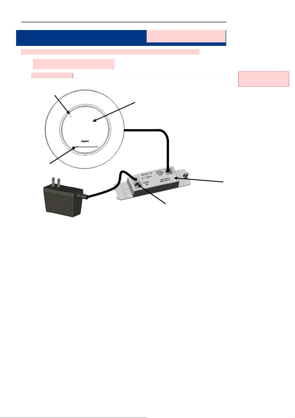
Installation Drawing :
Reset Button
LEDs
Figu
Dual Band WAP
Cat 5 cable
AC Adapter
re 2-1 DA1 1 0 4 Prod uct Installation Drawing
[MR1]: Drawing labels
need to be cleaned up
PoE Injector
From Internet
-7-
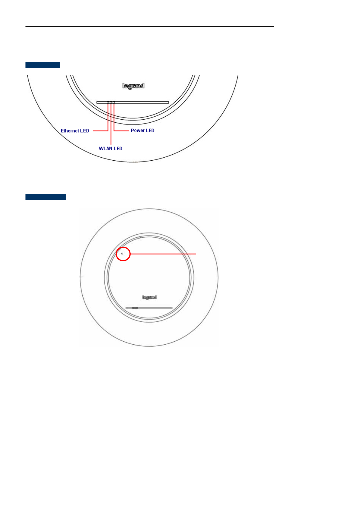
2.1.1 Panel Layout
The front and rear panel provide a simple interface monitoring the AP.
LED Interface
Figure 2-2 DA1104 Panel Layout - LED
Owner’s Manual of DA1104
Button definition
Reset Button
Figure 2-3 DA1 104 Pa ne l Layout – Reset Button
-8-
2.1.2 Hardware Description
LED definition
LED COLOR STATUS FUNCTION
Blue
PWR
Pink
Pink
Green
On Device power on
On Initializing
Blinking Signal Survey
On
The 2.4GHz WiFi is activated
Owner’s Manual of DA1104
Button definition
Port definition
WLAN
Green
Orange
Orange
Green
Ethernet
Green
Blinking The 2.4GHz WiFi is streaming in session
On
Blinking
On
Blinking
The 5GHz WiFi is activated
The 5GHz WiFi is streaming in session
Power Present
Ethernet active
Object Description
Reset
Press and hold the Reset button about 10 seconds and then release it. The
system restores to the factory default settings .
Object Description
PoE Port
(802.3af/at PoE)
10/100/1000Mbps RJ45 port , Auto MDI/ MDI-X
Connect PoE port to the IEEE 802.3af/at PoE injector to power on the device.
-9-

Owner’s Manual of DA1104
Chapter 3. Connecting to the AP
3.1 System Requirements
Broadband Internet Access Service (Cable/xDSL/Ethernet connection)
One IEEE 802.3af/at PoE switch (supply power to the DA1104 )
PC with a working Ethernet Adapter and an Ethernet cable w it h RJ45 connec tor s
PC running Windows 98/ME, NT4.0, 2000/XP, Windows Vista / Win 7/Win 8, MAC OS 9 or later, Linux,
UNIX or other platforms compatible with TCP/IP prot ocols
1. The AP in the following instructions refers to Legra nd DA1104.
2. It is recommended to use Internet Explorer 7.0 or above to access the AP.
3.2 Web configuration access
The default IP address of the DA1104 is 192.168.40.253. And the default Subnet Mask is 255.255.255.0. These
values can be changed, but in this manual, we use all the default values for examples.
Connect the DA1104 with your PC by an Ethernet cable plugging into the Data In port of the WAP connected
PoEn and into the Ethernet port of PC. Power on the DA1104 by plugging in the AC adapter of the PoE Injector.
In the following sections, we’ll introduce how to install and configure TCP/IP correctly in Windows 7 (other
operating systems are similar). First, make sure your Ethernet Adapter is working, and refer to the Ethernet
adapter manual if needed.
3.2.1 Configuring the IP Address Manually
Summary:
Set up the TCP/IP Protocol for your PC.
Configure the network parameters. The Ethernet Adapter of the PC should be configured for an IP
address of 192.168.40.xxx (the default IP address of the DA1104 is 192.168.40.253, and the default
router address is 192.168.40.254, the "xxx" can be configured to any number from 1 to 252), Subnet
Mask is 255.255.255.0.
1 Select Use the following IP address radio button, and then configure the IP address of the PC.
2 For example, as the default IP address of the DA1104 is 192.168.40.253 and the router is 192.168.40.254,
-10-

you may choose from 192.168.40.1 to 192.168.40.252.
Owner’s Manual of DA1104
Figure 3-1 TCP/IP Setting
Now click OK to save your settings.
Now, yo u can run the Ping comma nd in the command prompt to verify the network connection betw een your PC
and the AP. The following example is in Windows 7 OS. Please follow the steps below:
1. Click on Start > Run.
2. Type “cmd” in the Search box.
-11-
Owner’s Manual of DA1104
Figure 3-2 Windows Start Menu
3. Open a command prompt, type ping 192.168.40.253 and then press Enter.
If the result displayed is similar to Figure 3-3, it means the connection between your PC and the AP
has been established well.
Figure 3-3 Successful result of Ping command
If the result displayed is similar to Figure 3-4, it means the connection between your PC and the AP
has failed.
-12-
Owner’s Manual of DA1104
Figure 3-4 Failed Result of Ping Command
If the address is 0.0.0.0, check your adapter installation, security settings, and the settings on your AP. Some
firewall software programs may block a DHCP request on newly installed adapters.
3.2.2 Starting Setup in the Web UI
It is easy to configure and manage the AP with the web browser.
Step 1. To access the configuration utility, open a web-browser and enter the default IP address
http://192.168.40.253 in the web address field of the browser.
Enter the IP address of the AP
which by default is 192.168.40.253
Figure 3-5 Login by default IP address
After a moment, a login window will appear. Enter admin for the User Name and Password, both in lower case
letters. Then click the OK button or press the Enter key.
-13-
Default IP Address: 192.168.40.253
Default User name: admin
Default Password: admin
Owner’s Manual of DA1104
Figure 3-6 Login Window
If the above screen does not pop up, it may mean that your web-brow ser has been set to a proxy. Go
to T ools menu> Internet Options> Connections> LAN Settings on the screen that appears, cancel the
Using Proxy checkbox, and click OK to finish it.
-14-
Owner’s Manual of DA1104
Chapter 4. Configuring the AP
This chapter delivers a detailed presentation of AP’s functionalities and features under the main menu below,
allowing you to manage the AP with ease.
Figure 4-1 Main Menu
During operation, if you are not clear abo ut a certain f eature, you can refer to the “Help” section in the r ight side of
the screen to read all related helpful info.
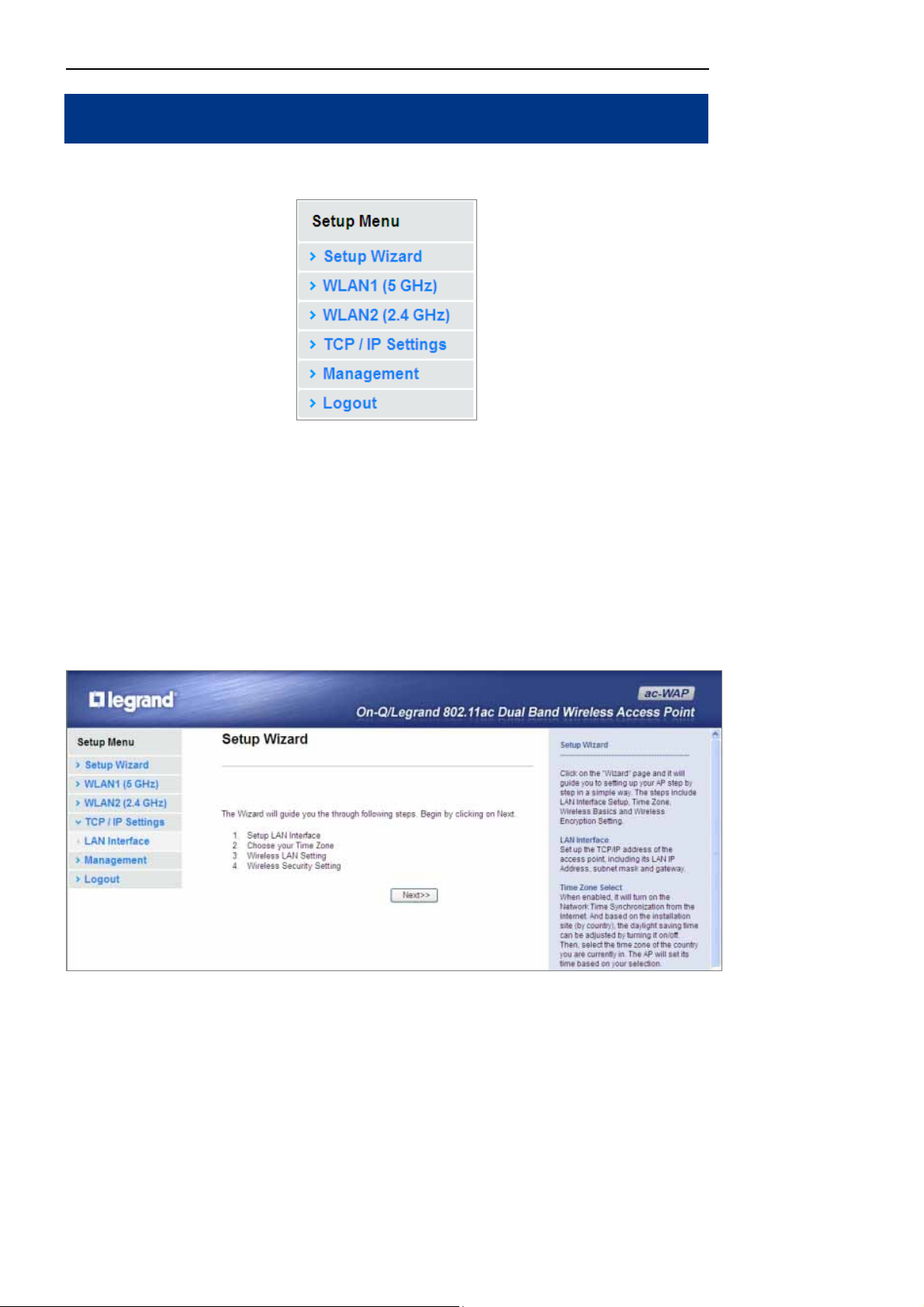
4.1 Setup Wizard
The Setup Wizard will guide the user to conf igure the DA1104 easily and quickly. Select the Setup Wizard on the
left side of the screen and by clicking on Nex t on the Setup Wiza rd sc reen show n below, you will then name your
DA1104 an d se t up its security.
Figure 4-2 Setup Wizard
-15-
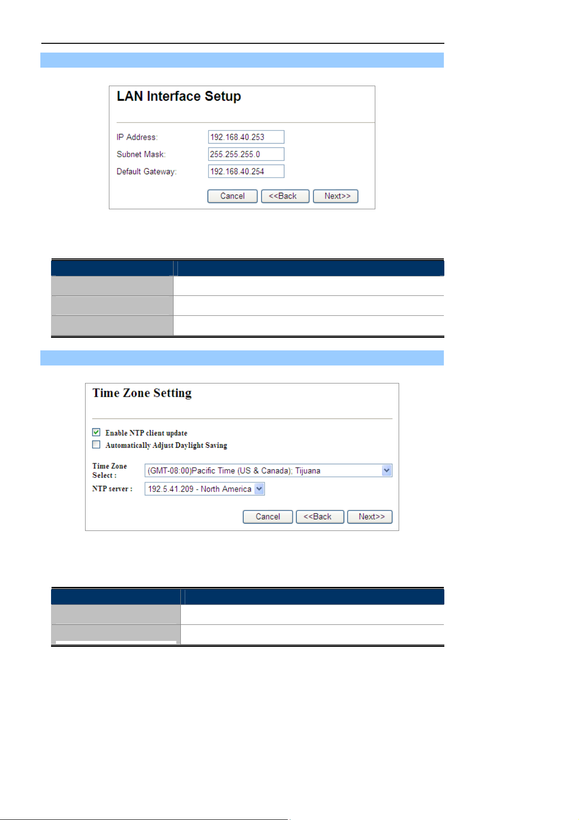
Step 1: LAN Interface Setup
Figure 4-3 Wizard – LAN Interface Setup
The page includes the following fields:
Object Description
IP Address
Displays the current IP address of the AP . (Defa ult = 192.168.40.253)
Owner’s Manual of DA1104
Subnet Mask
Default Gateway
Step 2: Time Zone Setting
The page includes the following fields:
Displays LAN mask of the AP. (Default = 255.255.255.0)
IP address of the associated router. (Default = 192.168.40.254)
Figure 4-4 Wizard – Time Zone Setup
Object Description
Enable NTP client update
Automatically adjust
Check this box to connect NTP Server and sy nchron ize internet time .
Check this box and system will adjust for daylight savings time
-16-
Owner’s Manual of DA1104
Daylight Saving
Time Zone Select
NTP Server
Enable NTP client update
automatically.
Select the Time Zone from the drop -down menu.
Select the NTP Server from the drop-down menu.
Check this box to connect NTP Server and sy nchron ize internet time .
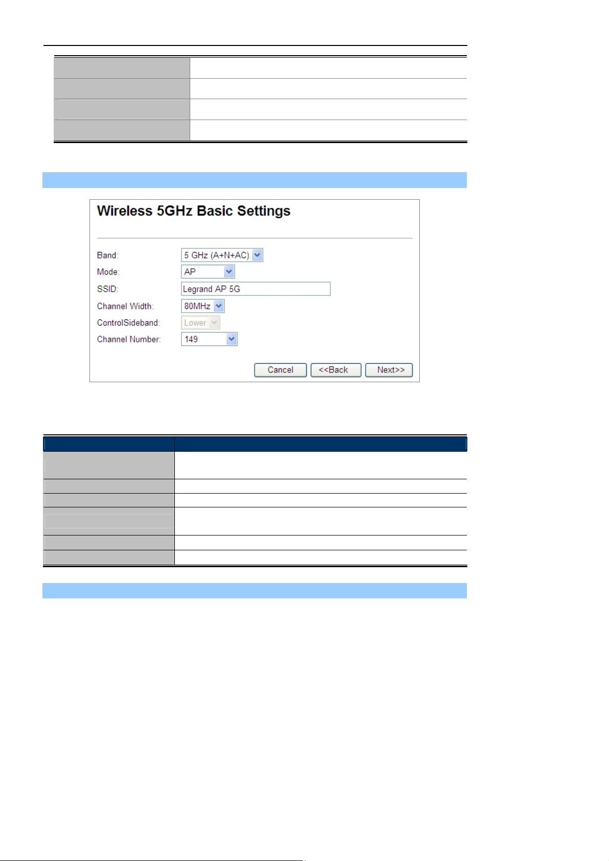
Step 3: Wireless 5GHz Basic Settings
Figure 4-5 Wizard – Wireless 5GHz Basic Settings
The page includes the following fields:
Object Description
Band
Mode
SSID
Channel Width
Control Sideband
Channel Number
Supports 802.11a, 802.11n, 802.11ac and mixed. Please choose its band
according to your clients.
Supports AP, Client, WDS and AP+WDS mode.
Service Set Identifier identifies your wireless network.
Select 80MHz if you use 802.11ac; select 40MHz if you use 802.11n;
otherwise, 20MHz for the 802.11a mode.
It is only valid when you choose channel width 40MHz.
Indicates the channel setting for the AP.
Step 4: Wireless 5GHz Security Settings
Secure your wireless network by turning on the WPA or WEP security feature on the router. For this section you
can set WEP and WPA-PSK security mode.
-17-
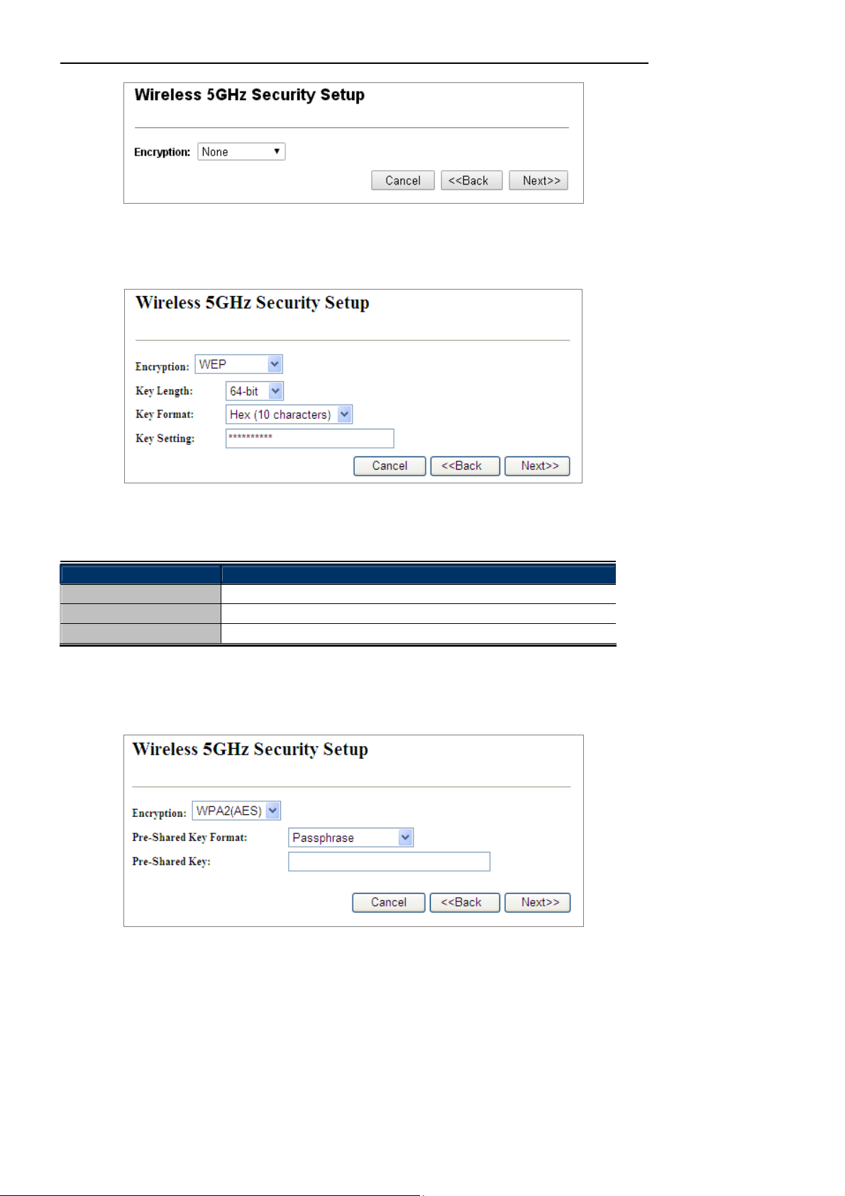
Figure 4-6 Wizard – Wireless 5GHz Security Setup
Encryption: WEP
The following picture shows how to set the WEP security.
Owner’s Manual of DA1104
Figure 4-7 5GHz Wireless Security Setup – WEP Setting
The page includes the following fields:
Object Description
Key Length
Key Format
Key Setting
WEP supports 64-bit or 128-bit sec urity key.
User can enter key in ASCI I or Hex format.
Enter the key whose format is limited by the Key format, ASCII or Hex.
Encryption: WPA-PSK
The following picture shows how to set up WPA-PSK security. You can select WPA (TKIP), WPA2 (AES) and
Mixed mode.
-18-
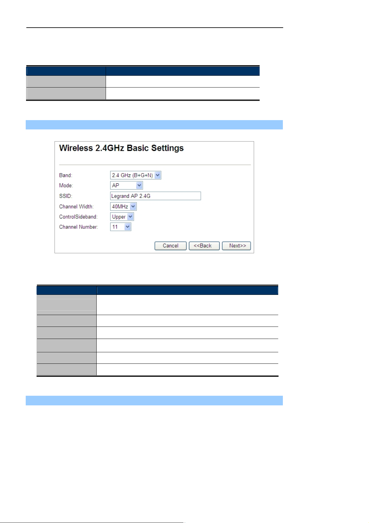
Figure 4-8 5GHz Wireless Security Setup – WPA Setting
The page includes the following fields:
Object Description
Pre-Shared Key Format
Specify the format of the key, pass phrase or hex.
Owner’s Manual of DA1104
Pre-Shared Key
Enter the key whose format is limited by the key format.
Step 5: Wireless 2.4GHz Basic Settings
Figure 4-9 Wizard – Wireless 2.4GHz Basic Settings
The page includes the following fields:
Object Description
Band
Mode
SSID
Channel Width
Control Sideband
Channel Number
Supports 802.11b, 802.11g, 802.11n and mixed. Please choose its band
according to your clients.
Supports AP, Client, WDS and AP+WDS mode.
Service Set Identifier, it ident ifi es y ou r wireles s network.
Select 40MHz if you use 802.11n, otherwise 20MHz for the 802.11b/g mode.
It is only valid when you choose channel width 40MHz.
Indicates the channel setting for the AP.
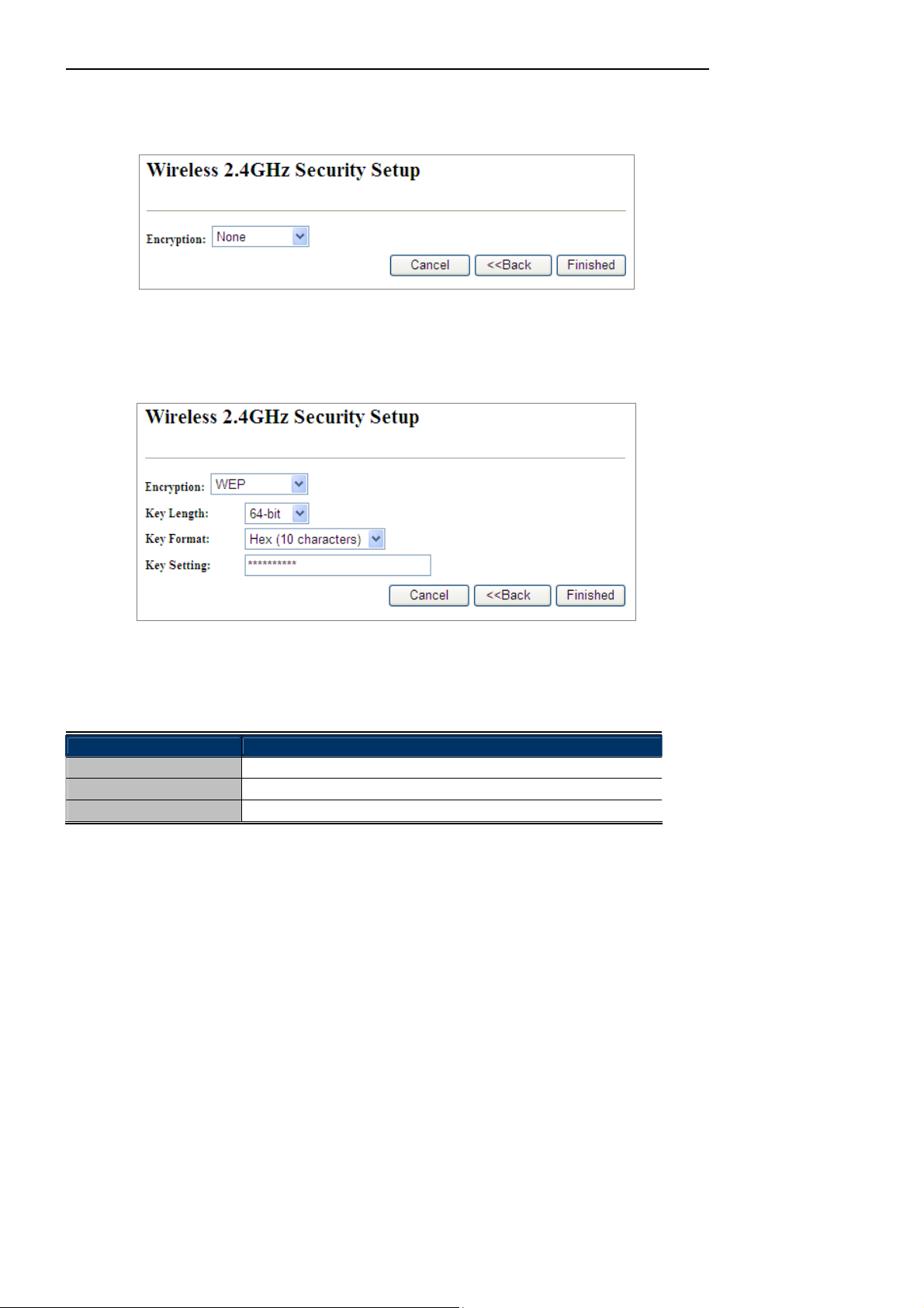
Step 6: Wireless 2.4GHz Security Settings
-19-
Owner’s Manual of DA1104
Secure your wireless network by turning on the WPA or WEP security feature on the router. For this section you
can set WEP and WPA-PSK security mode.
Figure 4-10 Wizard – Wireless 2.4GHz Security Setup
Encryption: WEP
The following picture shows how to set the WEP security.
Figure 4-11 2.4GHz Wireless Security Setup – WEP Setting
The page includes the following fields:
Object Description
Key Length
Key Format
Key Setting
WEP supports 64-bit or 128-bit sec urity key.
User can enter key in ASCI I or Hex format.
Enter the key whose format is limited by the Key format, ASCII or Hex.
Encryption: WPA-PSK
The following picture shows how to s et WPA-PSK security . You can select WPA (TKIP), WPA2 (AES) and Mixed
mode.
-20-
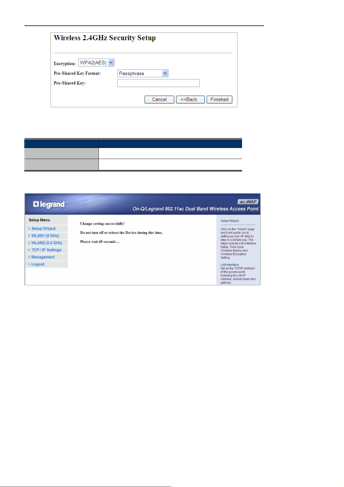
Figure 4-12 2.4GHz Wireless Security Setup – WPA Setting
The page includes the following fields:
Object Description
Pre-Shared Key Format
Specify the format of the key, pass phrase or hex.
Owner’s Manual of DA1104
Pre-Shared Key
Enter the key whose format is limited by the key format.
Click the Finished button to make your wireless configuration to take effect and finish the Setup Wizard.
Figure 4-13 Setup Wizard - Finished
After rebooting, please check whet her you can acce ss the Internet or not on the “Status” page.
-21-
 Loading...