

Pass and Seymour d b a Legrand DA1101 Users Manual

Wireless Access Point – N
(P/N DA1101)
Owner’s Manual
1308137 Rev. A
- i -

This device complies with Part 15 of the FCC Rules and RSS-210 Issue 8 of Canada. Operation
is subject to the following two conditions: (1) This device may not cause harmful interference
and (2) This device must accept any interference, including interference that may cause
undesired operation of the device.
Federal Communications Commission Statement
This device complies with Part 15 of the FCC Rules. Operation is subject to the following two
conditions:
• This device may not cause harmful interference, and
• This device must accept any interference received, including interference that may cause
undesired operation.
This equipment has been tested and found to comply with the limits for a class B digital device,
pursuant to Part 15 of the Federal Communications Commission (FCC) rules. These limits are
designed to provide reasonable protection against harmful interference in a residential installation.
This equipment generates, uses, and can radiate radio frequency energy and, if not installed and used
in accordance with the instructions, may cause harmful interference to radio communications.
However, there is no guarantee that interference will not occur in a particular installation. If this
equipment does cause harmful interference to radio or television reception, which can be determined
by turning the equipment off and on, the user is encouraged to try to correct the interference by one or
more of the following measures:
• Reorient or relocate the receiving antenna.
• Increase the separation between the equipment and receiver.
• Connect the equipment into an outlet on a circuit different from that to which the receiver is
connected.
• Consult the dealer or an experienced radio/TV technician for help.
Reprinted from the Code of Federal Regulations #47, part 15.193, 1993. Washington DC: Office of the Federal Register,
National Archives and Records Administration, U.S. Government Printing Office.
Canadian Department of Communications
This digital apparatus does not exceed the Class B limits for radio noise emissions from digital
apparatus set out in the Radio Interference Regulations of the Canadian Department of
Communications.
This Class B digital apparatus complies with Canadian ICES-003. Cet appareil numérique de la classe
B est conforme à la norme NMB-003 du Canada.
FCC Radio Frequency Exposure Caution Statement
In order to maintain compliance with the FCC RF exposure guidelines, this equipment should be
installed and operated with minimum distance 20cm between the radiator and your body. Use only
- ii -

with supplied antenna. Unauthorized antenna, modification, or attachments could damage the
transmitter and may violate FCC regulations. Any changes of modifications not expressly approved by
the grantee of this device could void the users authority to operate the equipment.
Installation and use of this Wireless LAN device must be in strict accordance with the instructions
included in the user documentation provided with the product. Any changes or modifications (including
the antennas) made to this device that are not expressly approved by the manufacturer may void the
user’s authority to operate the equipment. The manufacturer is not responsible for any radio or
television interference caused by unauthorized modification of this device, or the substitution or
attachment of connecting cables and equipment other than manufacturer specified. It is the
responsibility of the user to correct any interference caused by such unauthorized modification,
substitution or attachment. Manufacturer and its authorized resellers or distributors will assume no
liability for any damage or violation of government regulations arising from failing to comply with these
guidelines.
This device and its antenna(s) must not be co-located or operating in conjunction with any
other antenna or transmitter.
Declaration of Conformity (R&TTE directive 1999/5/EC)
The following items were completed and are considered relevant and sufficient:
• Essential requirements as in [Article 3]
• Protection requirements for health and safety as in [Article 3.1a]
• Testing for electric safety according to [EN 60950]
• Protection requirements for electromagnetic compatibility in [Article 3.1b]
• Testing for electromagnetic compatibility in [EN 301 489-1] & [EN 301]
• Testing according to [489-17]
• Effective use of the radio spectrum as in [Article 3.2]
• Testing for radio test suites according to [EN 300 328-2]
WARNING: TO PREVENT FIRE OR SHOCK HAZARD, DO NOT EXPOSE THIS PRODUCT TO
RAIN OR MOISTURE. THE UNIT MUST NOT BE EXPOSED TO DRIPPING OR SPLASHING
WATER.
CAUTION: DO NOT OPEN THE UNIT. DO NOT PERFORM ANY SERVICING OTHER THAN THAT
CONTAINED IN THE INSTALLATION AND TROUBLESHOOTING INSTRUCTIONS. REFER ALL
SERVICING TO QUALIFIED SERVICE PERSONNEL.
CAUTION: THIS DEVICE MUST BE INSTALLED AND USED IN STRICT ACCORDANCE WITH
THE MANUFACTURER’S INSTRUCTIONS AS DESCRIBED IN THE USER DOCUMENTATION
THAT COMES WITH THE PRODUCT.
WARNING: POSTPONE INSTALLATION UNTIL THERE IS NO RISK OF THUNDERSTORM OR
LIGHTNING ACTIVITY IN THE AREA.
- iii -

When using this device, basic safety precautions should always be followed to reduce the risk of fire,
electric shock and injury to persons, including the following:
• Read all of the instructions {listed here and/or in the user manual} before you operate this
equipment.
• Give particular attention to all safety precautions.
• Retain the instructions for future reference.
• Comply with all warning and caution statements in the instructions.
• Observe all warning and caution symbols that are affixed to this equipment.
• Comply with all instructions that accompany this equipment.
• Avoid using this product during an electrical storm. There may be a risk of electric shock from
lightning. For added protection for this product during a lightning storm, or when it is left
unattended and unused for long periods of time, unplug the power supply, and disconnect the Cat
5e to the N-WAP at the POE Inserter. This will prevent damage to the product due to lightning and
power surges. It is recommended that the customer install an AC surge protector in the AC outlet
to which this device is connected. This is to avoid damaging the equipment by local lightning
strikes and other electrical surges. A Data Surge Conditioning Unit is also available from Legrand
(P/N 364598-01) to help protect the data connection from the POE Injector to the N-WAP.
• Operate this product only from the type of power source indicated on the product’s marking label.
• If you are not sure of the type of power supplied to your home, consult your dealer or local power
company.
• Upon completion of any service or repairs to this product, ask the service technician to perform
safety checks to determine that the product is in safe operating condition.
Installation of this product must be in accordance with national wiring codes and conform to local
regulations.
Place POE Inserter to allow for easy access when disconnecting the power cord/adapter of the device
from the AC wall outlet.
Wipe the unit with a clean, dry cloth. Never use cleaning fluid or similar chemicals. Do not spray
cleaners directly on the unit or use forced air to remove dust.
When not utilizing the recommended 3-gang or 1-gang plastic switch & outlet box, do not directly
cover the device, or block the airflow to the device with insulation or any other objects.
Keep the device away from excessive heat and humidity and keep the device free from vibration and
dust.
- iv -

TABLE OF CONTENTS
Chapter 1 Introduction .......................................................................................................................... 1
Overview ....................................................................................................................................... 1
Package Content ........................................................................................................................... 1
Physical Details ............................................................................................................................. 1
Chapter 2 Physical Installation .............................................................................................................. 3
Physical Installation Steps ............................................................................................................. 3
Chapter 3 Network Settings .................................................................................................................. 4
Configuring and monitoring your DA1101 from web browser ......................................................... 4
Configuration of the DA1101 via web browser ........................................................................ 4
Starting Setup in Web UI ........................................................................................................ 5
Network Operation Mode ........................................................................................................ 9
LAN Interface Setup ............................................................................................................. 10
WAN Interface Setup ............................................................................................................ 11
Chapter 4 Firewall .............................................................................................................................. 18
Port Filtering ......................................................................................................................... 18
IP Filtering ............................................................................................................................ 19
MAC Filtering ........................................................................................................................ 20
Port Forwarding .................................................................................................................... 21
URL Filtering ........................................................................................................................ 22
DMZ ..................................................................................................................................... 23
VLAN .......................................................... .......................................................................... 24
Chapter 5 Wireless Settings ............................................................................................................... 25
Basic Settings ....................................................................................................................... 25
Advanced Settings ................................................................................................................ 28
Security Setup ...................................................................................................................... 30
Access Control ..................................................................................................................... 33
WDS Settings ....................................................................................................................... 34
Site Survey ........................................................................................................................... 34
WPS Settings ....................................................................................................................... 35
Wireless Schedule ................................................................................................................ 37
Chapter 6 Management ...................................................................................................................... 38
Status ................................................................................................................................... 38
Statistics ................................................................... ............................................................ 39
DDNS ................................................................................................................................... 39
Time Zone Setting ................................................................................................................ 40
Denial-of-Service ........................................................................ .......................................... 41
Log ....................................................................................................................................... 42
- v -

Upgrade Firmware ................................................................................................................ 43
Save / Reload Settings ......................................................................................................... 43
Password Setup ................................................................................................................... 44
Chapter 7 QoS .................................................................................................................................... 45
Enable QoS .......................................................................................................................... 45
QoS Rule Setting .................................................................................................................. 46
Chapter 8 Route Setup ....................................................................................................................... 47
Dynamic Route ..................................................................................................................... 47
Static Route .......................................................................................................................... 48
Appendix A Frequently Asked Questions List ................................................................................ A
Appendix B DA1101 Specifications ............................................................................................... B
- vi -

Chapter 1
Introduction
Overview
Integrating the cutting edge of Internet Telephony and Access Point manufacturing experience, Legrand
now introduces the latest member of our Wireless Access Point family: the DA1101 N-WAP.
The N-WAP provides high-performance Access Point (AP) function for flexible wireless communication.
With built-in IEEE 802.11b/g/n wireless network capability, the N-WAP allows any computer and wireless
enabled network client connect to it without additional cabling. The 802.11n wireless capability gives
users the highest speed of wireless experience ever. With an 802.11n compatible wireless adapter
installed in your PC, the files can be transferred at up to 300Mbps. The radio coverage is also doubled to
offer the high speed wireless connection in an even wider space of your office or house.
To secure the wireless communication, the N-WAP supports most up-to-date encryption: WEP, WPA-
PSK and WPA2-PSK. In addition, the N-WAP supports WPS configuration with PBC/PIN type for users
to connect to a secured wireless network easily.
Product Features
IEEE 802.11b/g/n wireless standard compliant
Multi-mode: AP, Client, Router Mode
Supports 64/128-bit WEP, WPA, WPA-PSK, WPA2, WPA2-PSK and 802.1x encryption
Package Content
The contents of your product should contain the following items:
DA1101 802.11n Wireless Access Point
POE Module w/AC adapter
Installation Bracket
Round and Rectangular Cover
Installation/Instruction Sheet
Physical Details
The following figures illustrate the 3-gang (round) and 1-gang (rectangular) versions of an installed
DA1101 N-WAP.
- 1 -
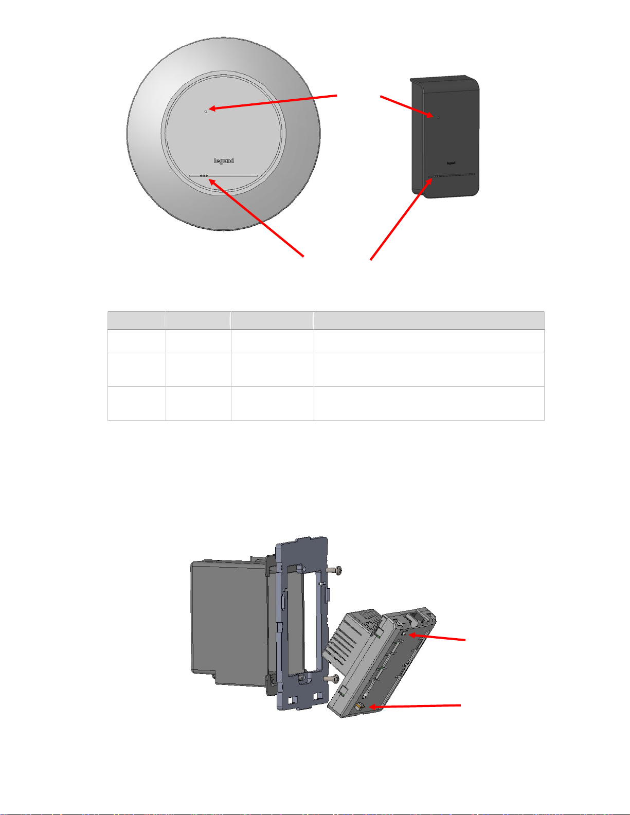
Reset Button
Access
LED Indicators
LED Indicators:
LED Color State Descriptions
Ethernet Green
Power Blue/Orange
WiFi Green/Red
Solid Green
Blinking Green
Blue
Solid Orange
Blinking Orange
Solid Green
Blinking Green
Red
Power Present
Ethernet Active
Power OK
Initializing
Signal Survey
Connected
Streaming in Session
No WiFi Signal
Reset Button:
The DA1101 has a reset button accessible through either cover or with the cover off that can be pushed
and held for 10 seconds to reset the DA1101 to factory default condition (the IP address is reset to
192.168.1.254).
Reset Button
- 2 -
LED Indicators
Chapter 2
Physical Installation
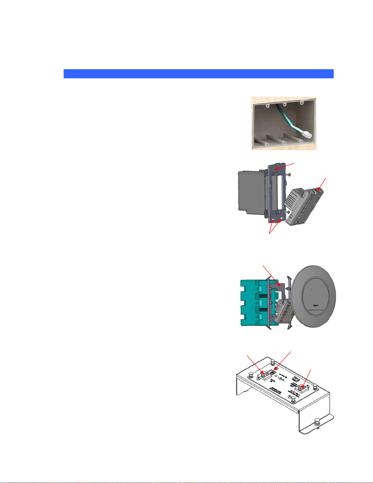
Physical Installation Steps
This chapter illustrates the physical installation of the DA1101 Wireless Access Point –N.
1. Run a Category 5 cable from the triple-gang or single-gang
electrical box at the intended DA1101 room location to the
POE module located in the structured wiring enclosure.
2. Make sure that the Power Supply is not connected to the
POE module at this time.
3. Pull the Category 5 cable out from the electrical box through
the supplied triple-gang or modified into a single-gang
bracket and attach the bracket to the associated electrical
box with the supplied screws.
4. Terminate the Cat 5 cable with an RJ45 plug and
connect it to the RJ45 jack on the DA1101. The DA1101
is then snapped into the mounting bracket by first
inserting the two tabs on one end into the slots on the
bracket and tilting it until it is flush with the bracket,
where it should snap into place.
5. If this is a triple-gang installation, line the feet on the
triple gang bracket up with the indentions inside the
round cover, and snap that cover in place. There is a
protrusion inside the round cover that allows it only to be
installed in the correct orientation. If this is a single-gang
installation, simply hang the top of the rectangular cover
on the single-gang bracket and tilt the cover to snap it
into place.
6. In the enclosure, terminate the other end of the Cat 5
cable from the DA1101 with an RJ45 plug and connect it
to the POE output RJ45 jack. A Cat 5 jumper is run from
the POE input jack to a local router port.
7. Plug the power supply into the POE module and into an
AC outlet, and refer to the next chapter for software
configuration and operation information.
- 3 -
Triple-gang bracket
Cat 5 to router
slots
Power in from AC adapter
Single-gang bracket
RJ45 jack
Cat 5 to N-WAP
Chapter 3
Network Settings
Configuring and monitoring your DA1101 from web browser
The DA1101 integrates a web-based graphical user interface that can cover most configurations and
machine status monitoring. Via a standard web browser, you can configure and check machine status
from anywhere around the world.
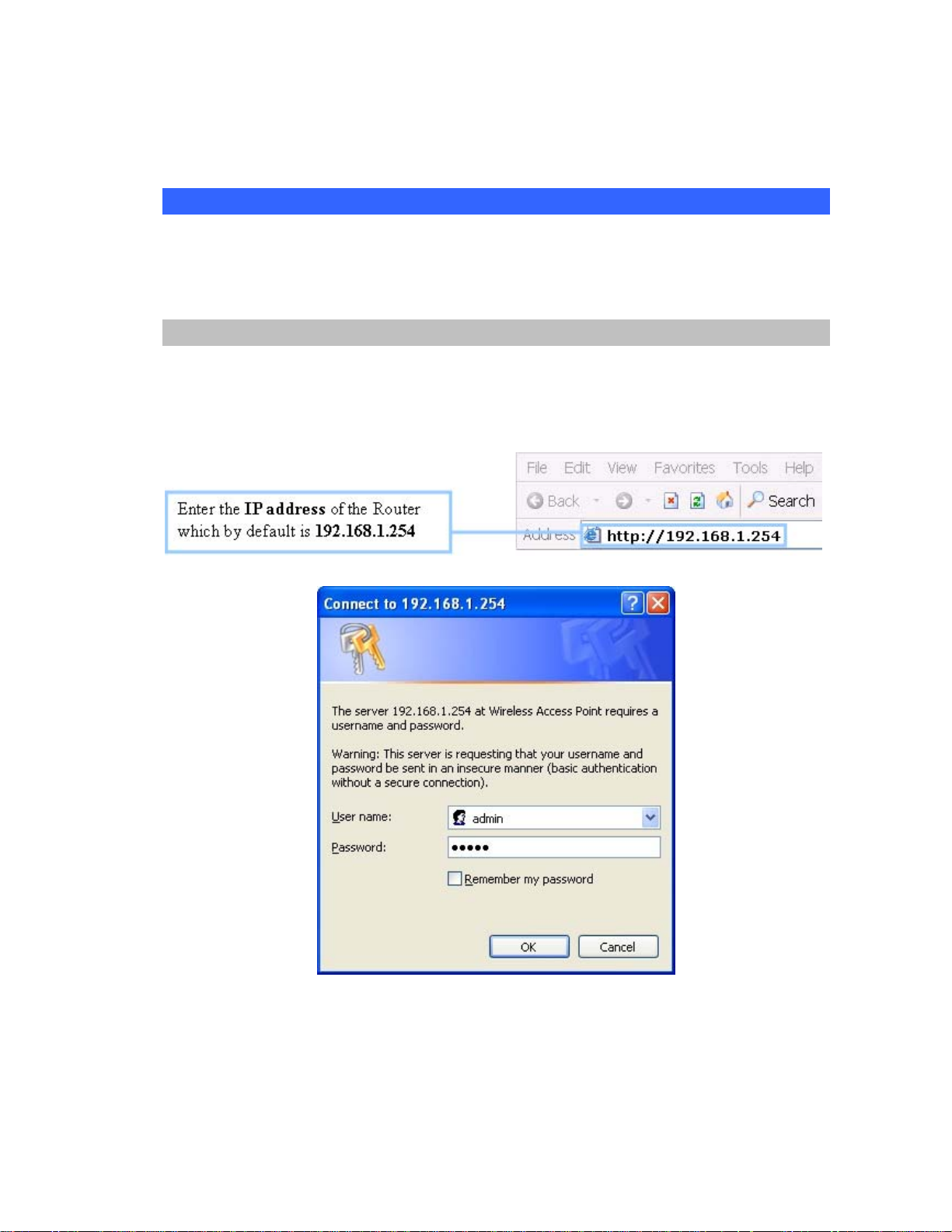
Configuration of the DA1101 via web browser
First insure that your PC is on the 192.168.1.xxx subnet (ie. 192.168.1.10) by configuring its IP
address to that subnet.
After TCP/IP configurations on your PC, you may now open your web browser, and input
http://192.168.1.254 (Default LAN port IP address) to logon to the DA1101 web configuration page.
The DA1101 will prompt for logon username/password: use admin / admin
DA1101 login prompt screen
- 4 -
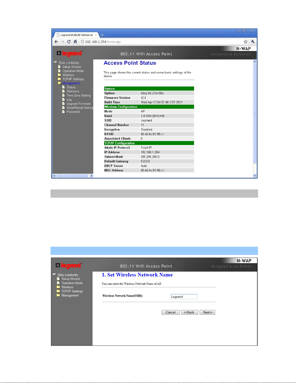
DA1101 main page
Starting Setup in Web UI
It is easy to configure and manage the DA1101 with a web browser. After successfully logging in, you
can click Setup Wizard to quickly configure your DA1101.
AP Mode is the default mode where the DA1101 works with a local router. The router provides
DHCP addressing to the wirelessly connected devices (PCs). An additional DA1101 may be
used as a repeater which allows for both directly connected LAN and wireless devices.
Step 1. Set Wireless Network Name (SSID), and then click Next>>.
- 5 -
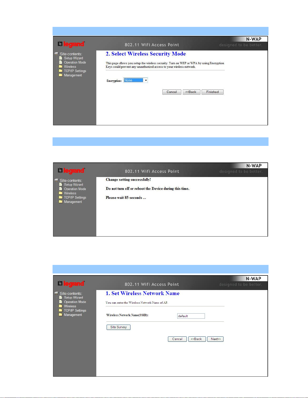
Step 2. Select Wireless Security Mode.
Step 3. Click the Finished button. You will then see the Finish page as shown below.
The DA1101 will reboot automatically to make your wireless re-configuration take effect and finish the
Setup.
Client Mode is used where an additional DA1101 is configured as the client and connects directly
to a LAN or PC (no wireless devices), while the original DA1101 connects to a router.
Step 1. Set Wireless Network Name, or click Site Survey to scan the nearby AP.
- 6 -
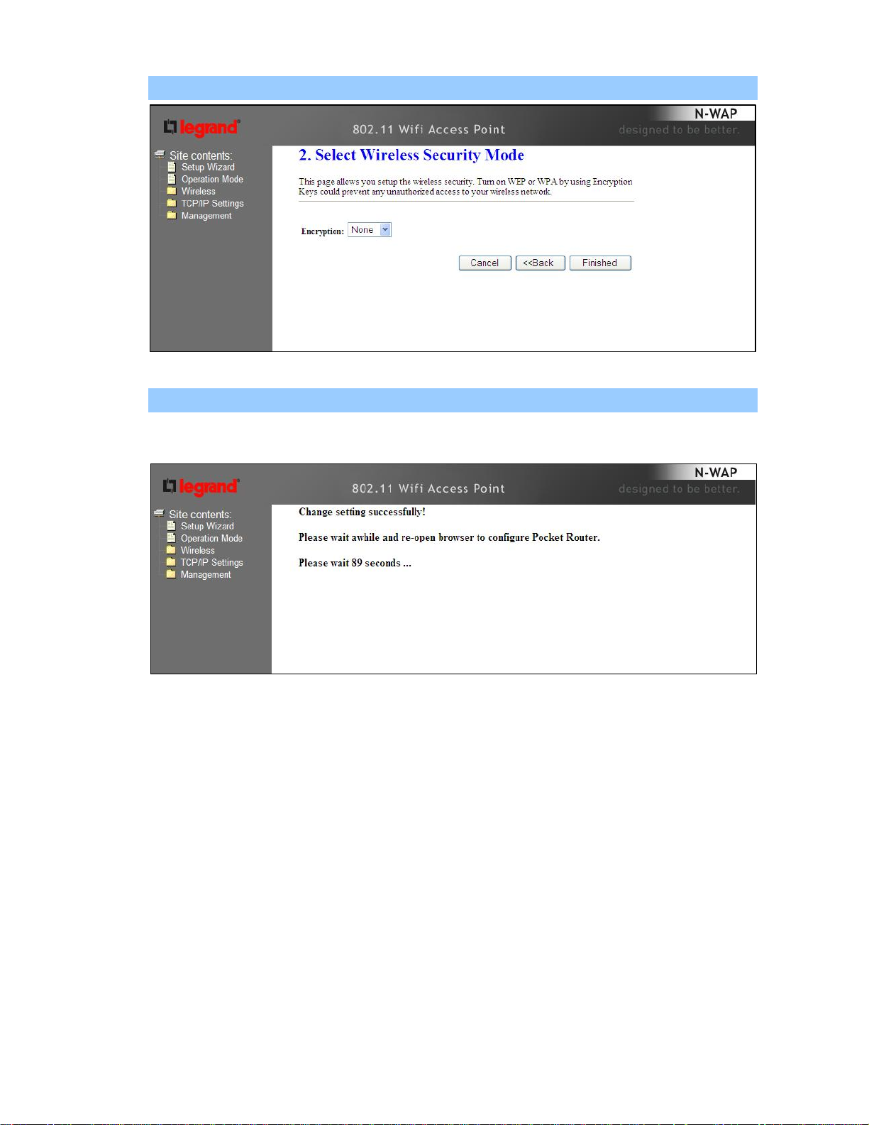
Step 2. Select Wireless Security Mode.
Step 3. Click the Finished button. You will then see the Finish page as shown below.
The DA1101 will reboot automatically to make your wireless configuration to take effect and finish the
Setup.
- 7 -
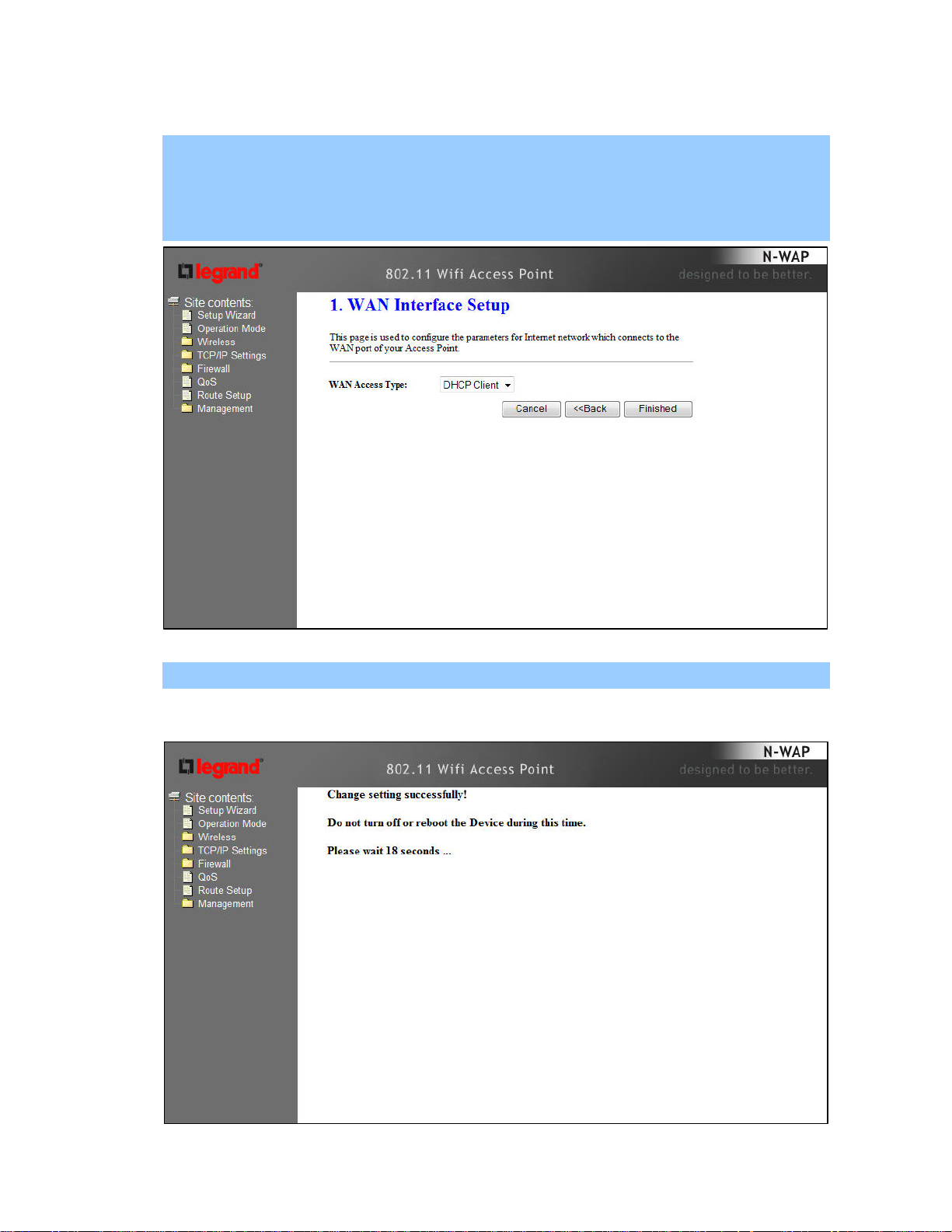
Router Mode is used when the DA1101 is connected to a cable modem and the DA1101 is
performing the routing functions, including providing DHCP addresses for devices (PCs).
Step 1. Select the WAN Access Type.
Step 2. Enter the information for the selected WAN Access Type, and then click Next. If your access
type is DHCP Client, then you can get the IP address from the ISP, so you do not need to
enter the information like other modes (see WAN Interface Setup section).
Step 3. Click the Finished button. You will then see the Finish page as shown below.
The DA1101 will reboot automatically to make your wireless configuration to take effect and finish the
Setup.
- 8 -
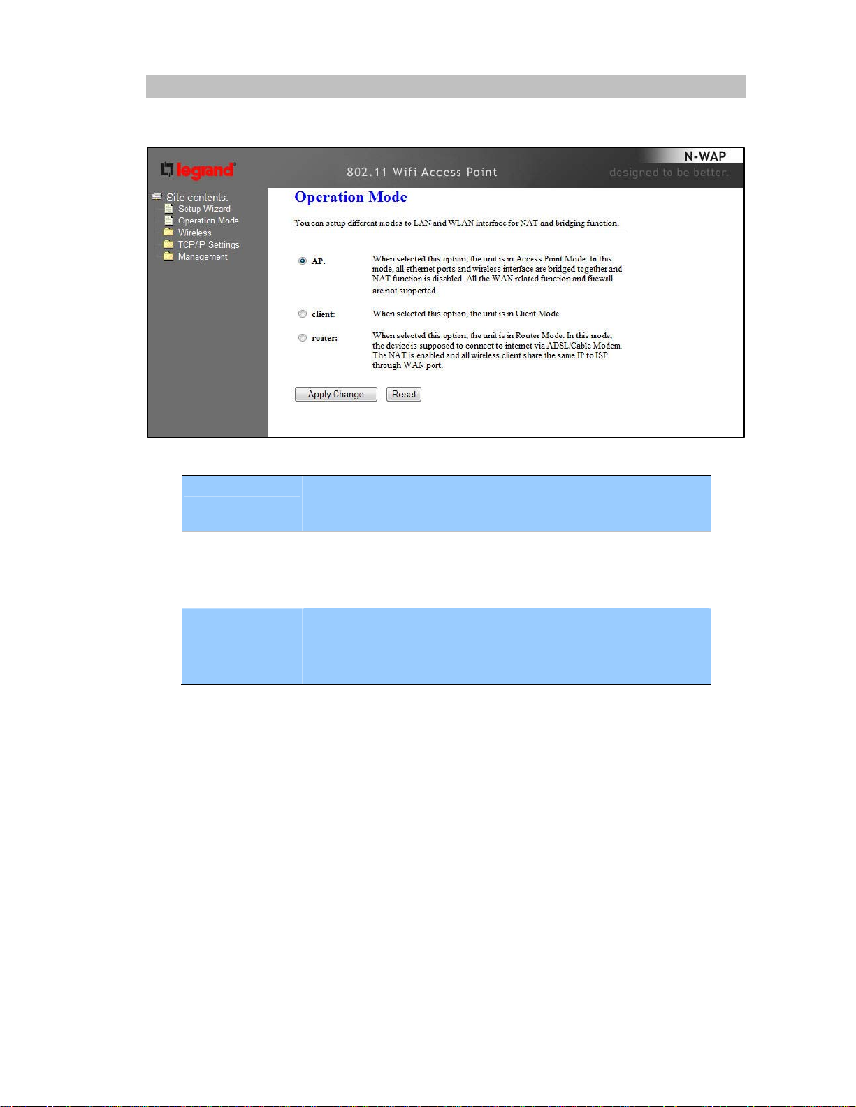
Network Operation Mode
You can setup different modes to WAN and LAN interface for NAT, Bridging and Wireless ISP
function.
In this mode, all Ethernet ports are bridged together and NAT
AP
function is disabled. All the LAN port related function and firewall are
not supported.
In this mode, all Ethernet ports are bridged together and the wireless
client will connect to ISP access point. The NAT is enabled and PCs
Client
in Ethernet ports share the same IP to ISP through wireless LAN.
You must set the wireless to client mode first and connect to the ISP
AP in Site-Survey page.
In this mode, the device is supposed to connect to internet via
ADSL/Cable Modem. The NAT is enabled and your PC in LAN port
Router
shares the same IP to ISP through WAN port. The connection type
can be setup in WAN page by using Static, DHCP Client, PPPOE,
PPTP or L2TP.
- 9 -
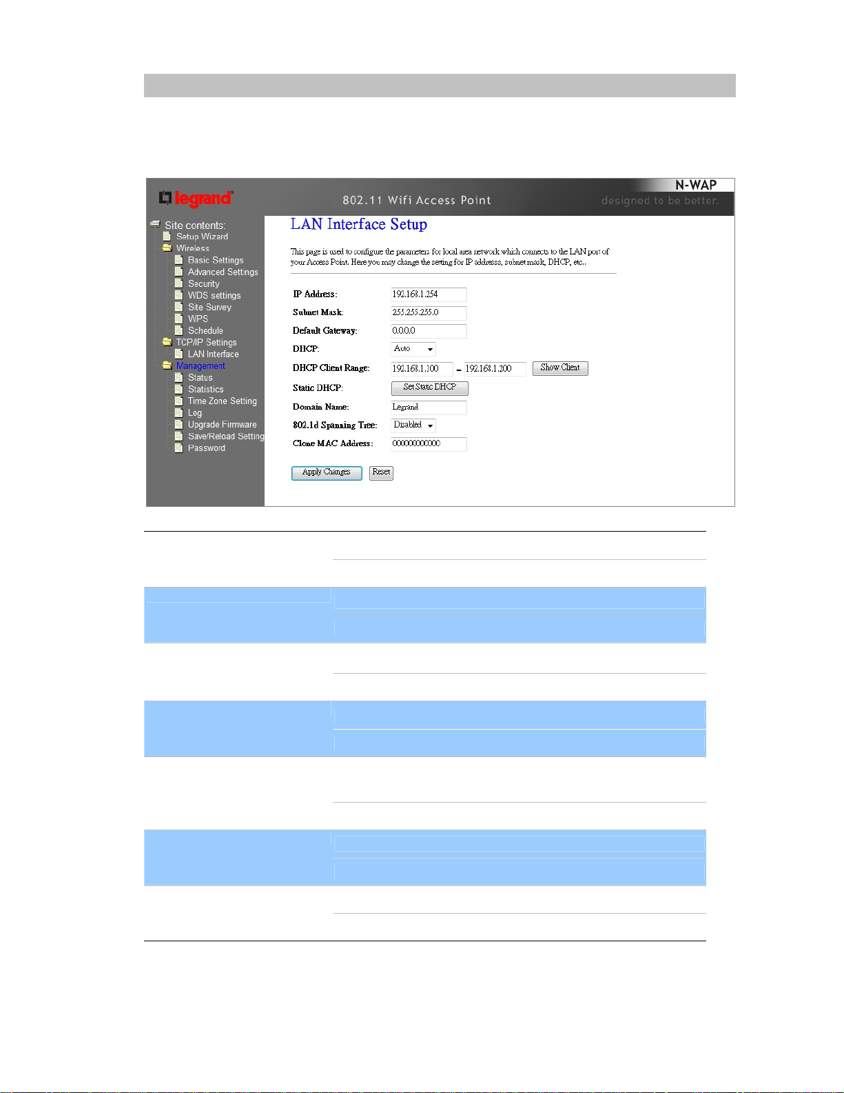
LAN Interface Setup
This page is used to configure the parameters for local area network which connects to the LAN port
of your DA1101. Here you may change the setting for IP address, subnet mask, DHCP, etc..
IP Address
LAN IP Address of the DA1101
Default : 192.168.1.254
Subnet Mask
LAN mask of the DA1101
Default : 255.255.255.0
DHCP Server You can select Server or Disable. If you select Disable, the
DHCP service of LAN port is disabled.
Default : Server
DHCP Client Range
The first and last IP address that DHCP server assigns.
Default : 192.168.1.100 – 192.168.1.200
Static DHCP It allows you reserve IP addresses, and assign the same IP
address to the network device with the specified MAC address
any time it requests an IP address
Default : Disable
Domain Name
Set three alternatives Domain Name Server for LAN interface.
Default : Null
802.11d Spanning Tree
Spanning Tree Protocol. You can select Enable or Disable.
Default : Disable
- 10 -

WAN Interface Setup
Choose menu “TCP/IP Settings→WAN Interface”, you can configure the IP parameters of the WAN on
the screen below when router mode is enabled.
DHCP Client
Connections which use dynamic IP address
assignment.
Static IP Connections which use static IP address assignment.
WAN Access Type
PPPoE
PPTP
L2TP
Connections which use PPPoE that requires a user
name and password.
Connections which use a Point-to-Point Tunneling
Protocol (PPTP) connection.
Connections which use a Layer2 Tunneling Protocol
(L2TP) connection.
Attain DNS Automatically Select to attain DNS automatically from your ISP.
Select to specify your own preferred DNS Server IP address.
Set DNS Manually
The DNS 2 or DNS 3 is optional. You can enter the secondary and the
third DNS Server’s IP address as an alternative of DNS 1.
Your ISP may require a particular MAC address in order for you to
connect to the Internet. This MAC address is the PC’s MAC address
Clone MAC Address
that your ISP had originally connected your Internet to. Type in this
section to replace the WAN MAC address with the MAC address of that
PC.
Enable uPNP Check to enable the uPNP function.
Enable IGMP Proxy Check to enable the IGMP Proxy function.
Enable Ping Access on
WAN
Enable Web Server Access
on WAN
Enable IPsec pass through
on VPN connection
Enable PPTP pass through
on VPN connection
Enable L2TP pass through
on VPN connection
Enable IPv6 pass through
on VPN connection
Apply Changes
Check to enable the Ping Access on WAN function.
Check to enable the Web Server Access on WAN function.
Check to enable the IPsec pass through on VPN connection function.
Check to enable the PPTP pass through on VPN connection function.
Check to enable the L2TP pass through on VPN connection function.
Check to enable the IPv6 pass through on VPN connection function.
After completing the settings on this page, click Apply changes button
to save the settings.
Reset Click Reset to restore to default values.
- 11 -
 Loading...