

WWPPSSSS 110000
WPSS100
Specifications are subject to change without notice
Innovation through technology since 1931
Installation Manual
and Operating Instruction
PPOORRTTAABBLLEE SSOOUUNNDD SSYYSSTTEEMMSS -- AACCCCEESSSSOORRIIEESS
TO REDUCE THE RISK OF FIRE OR ELECTRIC SHOCK DO NOT
EXPOSE THIS APPLIANCE TO RAIN OR MOISTURE
CAUTION !
Paso Sound Products, Inc. - 4750 F GOER DRIVE - CHARLESTON, SC 29406 - Phone: 843 308 9005 - Fax: 843 308 0904
®
SSoouunnddccaasstteerr
SSoouunnddccaasstteerr
®®
®®
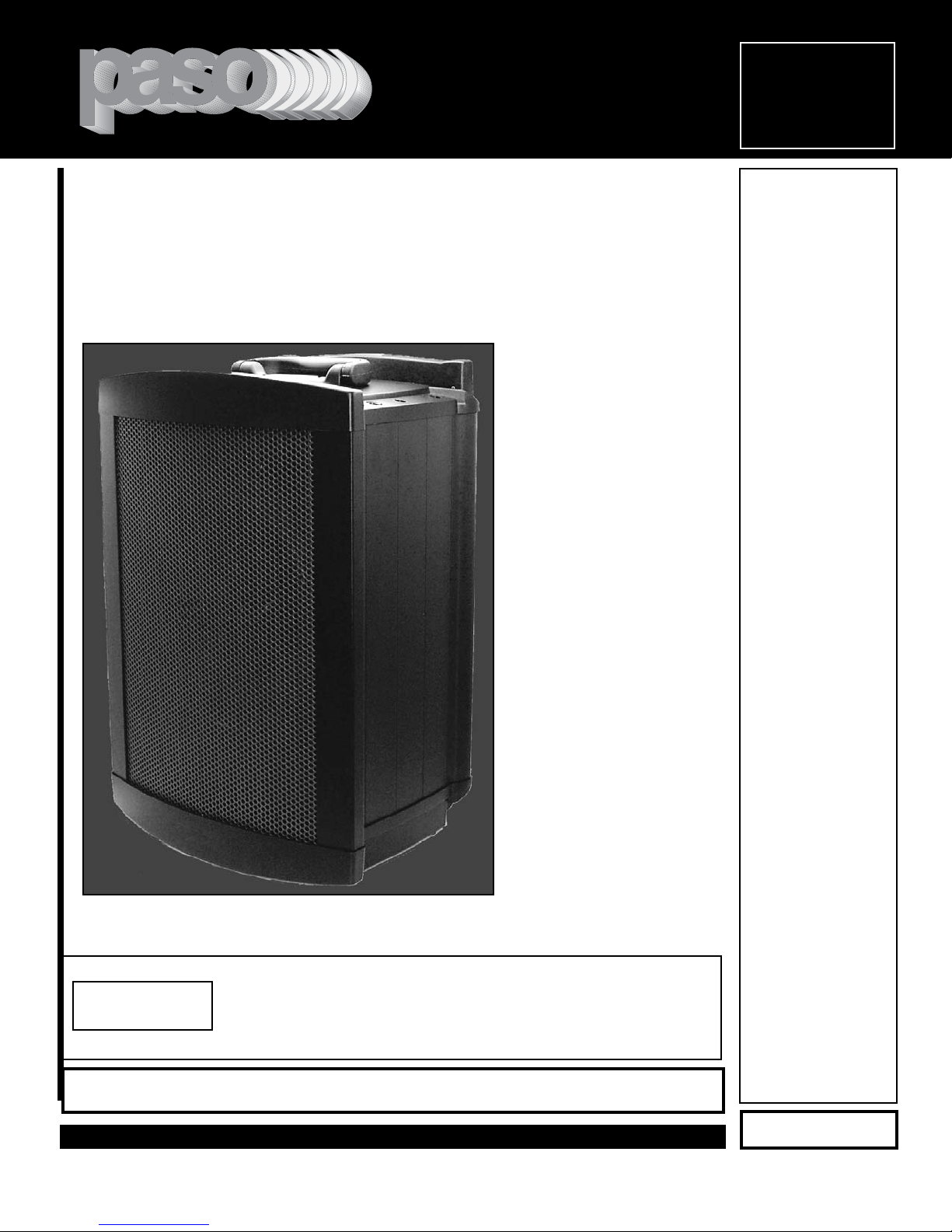
Portable Sound Systems
Manual
OOMM 222266
REV. 2.1
DIVERSITY
UHF WIRELESS
PROFESSIONAL AUDIO & SOUND

Soundcaster
®
PROFESSIONAL AUDIO & SOUND
®
PAGE 2
DESCRIPTION AND FEATURES SPECIFICATIONS
❑❑
4 Microphone Inputs - 2 Wired and
2 Wireless - 1 Line Input 1 Line Output
❑❑
Separate MIC 1, MIC 2, WMIC 1, WMIC 2,
LINE IN, MASTER Level Controls - TONE
❑❑
1 Line Output, 2 Speaker Outputs
❑❑
Active Output for system chaining
❑❑
MIC Inputs accept XLR Male and 1/4”
Phono Plug
❑❑
16 Channel UHF Diversity Wireless
Receiver provided
❑❑
16 Channel UHF Hand-Held
Microphone/Transmitter with ABS
Carrying Case provided
❑❑
Port for Second 16 Channel UHF
Receiver Module
❑❑
Separate Volume Controls for Wired and
Wireless Microphones
❑❑
Voice Priority Feature
❑❑
Wide Frequency Response Very Low
Distortion
❑❑
Indoor or Outdoor use
❑❑
Will cover an audience of 2000
❑❑
Operates on AC or DC with built-in
Rechargeable Battery
❑❑
Built-in Automatic Battery Recharger
❑❑
Wheeled with three position locking
trolley
❑❑
Automatic AC to DC Power Switchover
❑❑
Rugged Extrusion and ABS Enclosure
AUDIO
Amplifier Rating:
Power Output*:
THD:
SPL Max.:
Frequency response:
Inputs:
Inputs Impedance:
Outputs:
Speaker System 3 Way:
Controls:
Voice Priority:
Power Supply:
Internal Battery:
Battery Charge Time:
Battery Operating Time:
Battery Recharger:
Power Consumption:
WIRELESS SYSTEM
Antenna:
Carrier System:
Limiter Type:
Noise Reduction System:
Pilot Trigger T one;
Tone-code Frequency:
Receiver:
Receiver Port:
Receiver Model:
Microphone T ransmitter:
Microphone Xmtr Model:
Frequency Range:
CABINET
Material:
Color Finish:
Front Grille:
Trolley:
Casters:
Dimensions:
Net Weight:
Floor Stand Mount:
UNPACKING EQUIPMENT SUPPLIED
Immediately upon receipt of the WPSS100, inspect the unit
and shipping container for indications of improper handling
or in transit damage.The equipment was carefully inspected and tested before leaving the factory. Notify the
Transportation Company immediately if any damage is
found. ONLY THE CONSIGNEE CAN FILE A CLAIM WITH
THE CARRIER FOR DAMAGE DURING SHIPMENT. Be
sure to save the carton and packing material as evidence of
damage for the shipper inspection. DO NOT SHIP the unit
back to the factory unless authorized by the factory.
IN TRANSIT DAMAGES ARE NOT COVERED BY THE
PASO WARRANTY.
50 Watt RMS
100 Watt IPM (Program Material)*
< 0.5%
117 dB (at 1 W/ 1m)
40 Hz - 20 Khz ± 3 dB
MIC 1 - MIC 2 - LINE IN L/R - Wireless Mic 1 Wireless Mic 2 (Optional)
MIC1-2 = 250 Ohm Balanced. Line In = 47 K ohm
Line Out, External Speaker Switched, External
Speaker Unswitched
10” Full Range, 4” Mid Range, High Efficiency Tweeter
2 Microphone, 1 Auxiliary/Line In, Tone, Master
Volume. Wireless MIC Level on Receiver
Voice Priority Switch
117 V AC or 24 V DC with Inter nal Rechargeable
Battery.
(230 V 50-60 Hz model upon request)
2 X 12 Volt, 4.5 AH (in ser ies for 24V)
10 Hours
5-6 Hours Music - 7-8 Hours Speech
Built-in with Current Limiter
AC 170 VA, DC 150 W
Built-in UHF Diversity Antennas
Microprocessor Controlled PLL Synthesized
Optocoupler
Dual Band Compander
Yes
32.768 KHz
16 Channel with Selector, UHF Diversity Receiver (1)
provided
Optional Plug-In Second Receiver Port
PASO RM170U
16 Channel with Selector, UHF Hand-Held Microphone.
Dynamic Head. (1) provided.PASO MW165U
UHF 750 MHZ Band
Extruded Aluminum and ABS
Matte Black
Heavy Gauge Coated Steel
Collapsible Three Position Locking
Built-in Wheels
19.75" H., 13.75" W., 11.8" D.
(50 X 35 X 30 cm)
37 Lbs,
(16.8 Kg)
Optional Model B41B Floor Stand
B41B - Heavy Duty Collapsible Floor Stand.Black Finish.
MW163U - 16 Channel UHF Belt Pack Transmitter.
MW165U - 16 Channel UHF Hand Held Transmitter.
RM170U - 16 Channel, plug-in UHF Receiver Module.
PASS100 - Auxiliary Speaker System. Matches the
WPSS100. Includes casters and retractable trolley.
© copyright Paso Sound Products, Inc.2003 Specifications are subject to change without notice WPSS 100
OPTIONAL ACCESSORIES
WPSS100 - Soundcaster Portable Sound System
RM170U - 16 Channel Plug-in UHF Receiver Module
MW165U - 16 Channel UHF Hand Held Transmitter
ACC100 - Microphone/ Accessory Carry Case
MRCSD - Channel Select Screwdriver
OM226 - WPSS100 Operating Manual
27/636 - Power Cord

PAGE 3
SPECIFICATIONS ARE SUBJECT TO CHANGE WITHOUT NOTICE
Soundcaster
®
PROFESSIONAL AUDIO & SOUND
®
IMPORTANT SAFETY INSTRUCTIONS
READ BEFORE OPERATING READ BEFORE OPERATING
BEFORE OPERATING THE WPSS100, BE
SURE YOU FULLY UNDERSTAND ALL
INSTRUCTIONS AND FEATURES OF THE UNIT.
1) Read these instructions carefully.
2) Keep these instructions.
3) Heed all Warnings.
4) Follow all instructions.
5) DO NOT use this apparatus near water.
6) Clean ONLY with a damp cloth.
7) DO NOT block any of the ventilation openings.
Install in accordance with the instructions provided.
8) DO NOT install near any heat sources such as
radiators, stoves, or other apparatus that produce
heat.
9) DO NOT mount Soundcaster into a container or a
closed unventilated closet while operating.
10) DO NOT defeat the safety purpose of the polarized or grounding type plug. A polarized plug has two
blades with one wider than the other .A grounding type
plug has two blades and a third grounding prong.The
wide blade and or the third prong is provided for your
safety. When the provided plug does not fit into your
outlet, consult an electrician for replacement of the
obsolete outlet.
11) Use only the attachments and accessor ies specified in this manual.
12) DO NOT lift WPSS100 by trolley, use fixed handle.
13) Ensure trolley is in a positively locked position
before using.
14) Heavy duty floor stand must be properly deployed
on a level surface and positively locked before the
WPSS100 can be mounted.
15) Unplug this apparatus during lightning stor ms or
when unused for long periods of time.
16) Refer all servicing to qualified ser vice personnel.
Servicing is required when the apparatus has been
damaged in any way, such as power supply cord or
plug is damaged, liquid has been spilled or objects
have f allen into the appar atus, the appar atus has been
exposed to rain or moisture, does not operate normally, or has been dropped.
17) DO NOT replace fuse unless power cord is
removed from the AC wall outlet and power switch is
off.
18) DO NOT install accessories unless the power
cord is removed from the AC wall outlet and power
switch is off.
TO REDUCE THE RISK OF FIRE OR ELECTRIC
SHOCK DO NOT EXPOSE THIS APPLIANCE TO
WATER, RAIN OR MOISTURE
WPSS100 WITH TROLLEY EXTENDED WPSS100 MOUNTED ON FLOOR STAND

PAGE 4
SPECIFICATIONS ARE SUBJECT TO CHANGE WITHOUT NOTICE
Soundcaster
®
PROFESSIONAL AUDIO & SOUND
®
OPERATION PROCEDURES
IMPORTANT!
After unpacking the unit for the first time, please
charge the lead acid batteries for at least 10 hours
before any operation.The batter ies were fully
charged in the factory before shipment.To charge the
batteries, just plug in the AC supply and charging will
start automatically.In the charging process, the
charging indicator will be flashing.
To Operate Using AC Power Supply
Switch on the main power supply switch.The AC
power supply is designed to provide the power for the
system while charging the batteries.
When the charging indicator is GREEN the batteries
are fully charged and non AC operation can now be
started. This main power supply DOES NOT switch
on the receiver modules.
To Operate Using the Rechargeable Batteries
Switch on the main power supply switch.When batteries are charged, the power supply indicator will be
GREEN.When the power supply indicator is RED the
built-in batteries are weak. Please charge the batteries first before using or you can also operate it while
charging.This main power supply DOES NOT switch
on the receiver modules.
To operate the casstte deck or CD player, please
switch on the TAPE / CD switch (DISABLED
THIS
MODEL).
To Operate the Receiver Module
Switch on the power/ volume switch located on the
receiver module front panel. Adjust volume. (the module and transmitter must be on the same frequency to
operate properly)
Operating the Wireless Microphone System
To use the wireless system, make sure that all volume knobs are set to minimum levels before turning
the unit on, switch on the receiver power/ volume
switch on the receiver control panel.Switch on the
corresponding matching wireless microphone transmitter ( please refer to the operating instructions of
the individual transmitter ).When RF signal is being
received by the receiver, the receiver RF diversity signal indicator A or B on the control panel will light up.
Rotate the power/ volume control knob on receiver
control panel and the Master volume control clockwise to the desired levels.
To use the second wireless system, repeat the above
on the second receiver module.
Operating Wired Microphones
To use microphone one, simply plug in the microphone cable connector into the XLR / Phono jack
combo connector on MIC 1 control panel.This unique
connector accepts either XLR or 1/4" male phono
jack connector. Rotate the volume control clockwise
on MIC 1 control panel and the Master volume control to increase the volume.
To use microphone two, simply plug in the microphone cable connector into the XLR / Phono jack
combo connector on MIC 2 control panel. Rotate the
volume control clockwise on MIC 2 control panel and
the Master volume control to increase the volume.
Both wired and wireless microphones can be used
simultaneously utilizing the built-in mixer.

PAGE 5
SPECIFICATIONS ARE SUBJECT TO CHANGE WITHOUT NOTICE
Soundcaster
®
PROFESSIONAL AUDIO & SOUND
®
OPERATION PROCEDURES
Audio Link Master / Slave Operation
In order to operate Audio Link, you must have a unit
that operates as a MASTER (only one unit is allowed
to act as MASTER and the other(s) MUST operate as
SLA VE(s).A MASTER unit is capable of connecting up
to 20 SLAVE units via daisy chain method.
To operate Audio Link, connect the Output jack of the
MASTER to the Audio Link IN jack of the 1st SLAVE
unit. The Output jack of this SLAVE should be connected to the Input jack of the 2nd SLAVE unit. Similar
connection shall continue as such for the following
SLAVE units.
Volume Control for SLAVE
When used on the SLAVE unit, it only controls that
particular units volume.
Maximum number of SLAVE units to be connected
with a MASTER is 20.
Voice Priority Operation
Voice Priority operation will only be enabled when
there is a source input into Line in.
When the Voice Priority switch is put to the ON position, the attenuating function will be activated. While
the music is playing, a voice input from either a Wired
or Wireless Microphone will temporary turn down the
volume of the background music. Background music
will return to its original setting when a signal from the
microphone is no longer sensed. Voice priority is best
operated using microphones with a push to talk or on
/ off switch.
Battery Charging
Internally, the WPSS100 contains two 12V / 4.5AH
maintenance-free lead acid batteries, which have no
memory effect.
When the battery is weak, the power indicator will be
RED when the main power switch is on.
To charge the battery, simply plug in the AC power
supply, the charging process will start automatically.
While charging, the charging indicator will be flashing.
When battery is fully charged, the charging indicator
will stay GREEN.
Speaker Out ( unswitched )
When an external speaker is connected to this output,
both the internal speaker of WPSS 100 and the external speaker will have sound.
Speaker Out ( switched )
When an external speaker is connected to this output,
the internal speaker of WPSS100 will be muted and
only the external speaker will have sound.
Trolley Release Button
This button serves to release the locking mechanism
of the trolley. To pull out the first stage of the handle,
one does not have to press the button to release it.To
pull the second and third stages of the handle, press
the release button to unlock the mechanism.
To put back the handle, press the release button to
unlock the mechanism and return the handle to its
original position.
All Soundcaster enclosures have identical mechanical parts as follows :1-Antenna slots (future expansion) 2-Cabinet handle 3-Trolley release button 4-Three stage trolley 5-Wheels 6-Heavy duty stand bracket
NOTE
: Please be advised that the trolley and wheels are meant for moving around on smooth surfaces and short distances only. It is NOT meant
or built for heavy duty long distance transportation on rough surfaces. DO NOT use the trolley as a handle for lifting or going up and down stairs.
For these purposes use the fixed cabinet handle ( 2 ).
MECHANICAL PARTS
1
2
3
4
5
6

PAGE 6
SPECIFICATIONS ARE SUBJECT TO CHANGE WITHOUT NOTICE
Soundcaster
®
PROFESSIONAL AUDIO & SOUND
®
INSTALLATION AND OPERATION
PROFESSIONAL AUDIO & SOUND
RECEIVER MODULE
POWER/ VOLUME CONTROL
Tur ns power on to module and controls volume level.
CHANNEL SELECTOR SWITCH
Changes the modules channel to correspond with
matching channel of transmitter. (Please use screwdriver provided)
DIVERSITY CHANNEL INDICATOR LED
Indicates which diversity channel the module is currently operating on.
POWER INDICATOR LED
Indicates when the module is energized.
PANEL CONTROLS
MIC 1 / MIC 2
Neutrik XLR / Phone combo connector allows wired
microphone with XLR as well as Phone Jack connectors to be plugged in.
Vol. Controls for wired microphone MIC 1 and MIC 2
TAPE / CD CONTROL
Power ON switch and Volume control for Tape / CD
player (DISABLED THIS MODEL)
AUDIO LINK ACTIVE OUT
Active Out jack to SLAVE unit. Maximum number of
SLAVE units to be connected with a MASTER in a
daisy chain is 20.
LINE IN / LINE OUT
Standard RCA jack for LINE IN / OUT
LINE IN volume control
TONE CONTROL
Tone control for Bass / Treble
MASTER VOLUME CONTROL
Controls the mixed output volume of the MASTER unit
as well as all the following SLAVE units.
VOICE PRIORITY SWITCH
Activates voice priority function.
POWER SUPPLY AND BATTERY INDICATOR
MAIN POWER SWITCH ON/OFF
Power Supply (weak battery) indicator RED
Power Supply (good battery) indicator GREEN
REAR PANEL CONTROLS
PLL DIVERSITY RECEIV ER P LL DIV ERSIT Y R ECEIV ER
99
111
1
77
RFRF
3
131
55
33
5
151
11
AA BB
CHCH
®
UHFUH F
AFAF
POWER/MINPOWER /MIN MAXMAX
POWER POWE R
PORT FOR OPTIONAL PLL
UHF RECEIVER MODULE
PUSH
MIC-1 IN
OUT
(SWITCHED)
CAUTION
It is necessary to recharge
the internal battery for at least
10 hours prior to the initial
operation.
117 V 60 HZ
AC - 170 VA
PUSH
MIC-2 IN ACTIVE OUT
CAUTION
RISK OF ELECTRIC SHOCK
WARNING: THIS APPLIANCE
MUST BE EARTHED
OUT
WARNING:
TO REDUCE THE RISK OF FIRE
OR ELECTRIC SHOCK, DO NOT EXPOSE THIS
8 OHM
APPLIANCE TO WATER, RAIN OR MOISTURE .
PROFESSIONAL AUDIO & SOUND
SOUNDCASTER
TAPE/CD
OUTOU T ININ
DO NOT OPEN
O
LINE
CAUTION: TO REDUCE THE
RISK OF FIRE, REPLACE
ONLY WITH SAME TYPE
FUSE.
CHARGING
INDICATOR
O
MODEL - WPSS100
CHANNELS MHZ - RM170U
750.350 751.100 751.525 752.775
753.750 754.850 755.875 757.925
759.550 761.750 764.525 765.100
765.925 767.025 768.150 768.750
®
TONE
MASTER
FUSE 5 A
Power Consumption
SERIAL NO.
DC
DC - 150W
TM

PAGE 7
SPECIFICATIONS ARE SUBJECT TO CHANGE WITHOUT NOTICE
Soundcaster
®
PROFESSIONAL AUDIO & SOUND
®
Before operation, please check and make sure that
transmitter & receiver are of matching frequency or frequency group (for PLL version). For PLL version, further verify that the channel selected at both ends are of
the same.
To switch on the microphone, put the switch to "ON"
position.The GREEN LED will indicate that the battery
is fresh. When RED LED is on it indicates that the battery is weak and needs replacement.
For best results, an alkaline battery is recommended.
Please remove the battery if the transmitter is not to be
used for longer periods of time.
For close singing or speaking, put the sensitivity
switch to N (Normal). For stage applications, where the
speaker stands away from the microphone, put the
sensitivity switch to H (High). Speaking loudly and
closely into the microphone in the high sensitivity
position may cause output distortion.
When holding the microphone, do not cover the end of
the unit.This is where the antenna assembly is located
and transmission efficiency may be effected.
WIRELESS MICROPHONE OPERATION PROCEDURE
MW165U uses a 9V battery for power .To change
or replace the battery, remove the antenna cap
first, then press the bottom of battery compartment to release the cover as shown in the figure
below.
OPERATING INSTRUCTIONS
BATTERY INSTALLATION RECEIVER MODULE INSTALLATION
To install an additional receiver module, first
remove the two screws from the blank panel that
covers the module compartment. Position the
module so that it will exactly slide into the guide
rails within the compartment, push in the module
so that the gold contact connector plugs firmly
into the rear socket.To secure the receiver module to the WPSS100 rear panel, tighten the
receiver panel with two screws.
®
PROFESSIONAL AUDIO & SOUND
UHFUHF
PLL DIVERSITY RECEIVER PLL DIVER SITY RECE IVER
99
111
1
77
RFRF
3
131
55
33
5
151
11
AA BB
CHCH
POWER/MINPOWE R/MIN MAXMAX
AFAF
POWER POWE R
PORT FOR OPTIONAL PLL
UHF RECEIVER MODULE

PAGE BACK
REPLACEMENT PARTS
Please provide complete information when you request replacement parts from either the Factory or a Paso Authorized
Distributor. Be certain to include the Part Number and
Description as it appears on the parts list, the Model Number of
the unit and if possible the Serial Number and the date of purchase of the unit. Replacement parts inventory is maintained
specifically to repair Paso products.Part sales for other reasons
or applications will be declined.
ORDERING FROM THE FACTORY
Print all information on a purchase order form and mail to:
PASO SOUND PRODUCTS, INC.
4750 Goer Drive - Building F
CHARLESTON, SC 29406
Be sure to include the following:
- Paso part number
- Part description
- Quantity required
- Model number of the unit
- Serial number of the unit
- Your payment or your authorization for COD shipment for parts
not covered by the Warranty or if your company has a current
account with the factory
RETAIN ORIGINAL PARTS (IN WARRANTY) UNTIL YOU
RECEIVE REPLACEMENTS. DEFECTIVE PARTS THAT
SHOULD BE RETURNED TO THE FACTORY WILL BE LISTED
ON YOUR PACKING SLIP.
For your convenience replacement parts are also available
through Paso Authorized Distributors and Dealers nation wide.
Obtain a location list directly from the Factory or your regional
Paso Representative.
TECHNICAL CONSULTATION
- Need help with your installation ?
- Need help with the operation of the unit ?
- Need help with a repair ?
Call or write for assistance. You will find our Technical Dept.
eager to help or assist you with any technical problem you may
have encountered except “`Customizing'' for a unique application.
The effectiveness of our consultation service depends on
the accuracy of the information you furnish.
Be sure to tell us:
- The Model and Serial number of the unit
- The date of purchase
- An exact description of the difficulty
- All trouble-shooting done in attempting to correct the problem
Call our toll-free phone number:
1-800 231 3034
CUSTOMER SERVICE
REPLACEMENT PARTS REPAIR SERVICE
REPAIR SERVICE
Repair service for out of warranty Paso products may be
obtained form your local Paso distributor or any other qualified
repair station.
In warranty repairs must be returned to the Factory.
Prior authorization must be obtained from the Factory.
Products received without authorization will be refused by our
Receiving Department.
IN WARRANTY REPAIR SERVICE
Call or write the Factory to obtain an authorization to return
the product for repairs.
Pack the equipment in the original carton or in a strong carton
with at least THREE INCHES of resilient packing material on all
sides, top and bottom. Seal the car ton with reinforced tape and
mark it FRAGILE on at least two sides. Remember, the Carrier
will not accept liability for shipping damages if the unit is improperly packed.
EQUIPMENT RECEIVED IN DAMAGED CONDITION DUE TO
POOR PACKING WILL BE REFUSED AND THE WARRANTY
COVERAGE IS AUTOMATICALLY VOIDED.
The Paso Sound Limited Warranty provides:
The examination of the returned product must disclose in our
judgement, a manufacturing defect. The warranty does not
extend to any product that has been subject to misuse, neglect,
accident, improper installation or where the serial number of the
product has been removed or defaced.
Ship via insured prepaid United Parcel Service or Parcel Post to:
PASO SOUND PRODUCTS, INC.
4750 Goer Drive - Building F
CHARLESTON, SC 29406
ATTN. SERVICE DEPARTMENT
The equipment will be returned freight prepaid after repairs.
Be sure to include the following:
- Your name and address
- Date of purchase and copy of invoice
- A brief description of the difficulty
- A return address shipping label
-
OUT OF WARRANTY REPAIR SERVICE
Follow return instructions as per in warranty repair service.Prior
to performing all necessary repairs, you will be advised of the
charges and at that time a written authorization by you will be
required including authorization to return the equipment COD for
the service and shipping charges. This will avoid unnecessary
delays in returning the equipment to you.
Printed in USA Manual OM 226
Soundcaster®
PROFESSIONAL AUDIO & SOUND
®
 Loading...