

Installation Manual
and Operating Instructions
Wireless Microphone System
Paso Sound Products, Inc.
Web site: http://www.pasosound.com E-mail: info@pasosound.com
4750 F Goer Drive - Charleston, South Carolina 29406 / TEL: 1-800-231-3034 FAX: 843-308-0904
RDU216/ MW163U
RDU216/ MW165U
PROFESSIONAL AUDIO & SOUND
®
PROFESSIONAL AUDIO & SOUND
®
CAUTION !
TO REDUCE THE RISK OF FIRE OR
ELECTRIC SHOCK DO NOT EXPOSE
THIS APPLIANCE TO RAIN OR MOISTURE
Manual
OM 216
REV. 2.2
REPLACEMENT PARTS
Please provide complete information when you request
replacement parts from either the Factory or a Paso Authorized
Distributor. Be certain to include the Part Number and Description
as it appears on the parts list, the Model Number of the unit and if
possible the Serial Number and the date of purchase of the unit.
Replacement parts inventory is maintained specifically to repair
Paso products. Part sales for other reasons or applications will be
declined.
ORDERING FROM THE FACTORY
Print all information on a purchase order form and mail to:
PASO SOUND PRODUCTS, INC.
4750 Goer Drive - Building F
CHARLESTON, SC 29406
Be sure to include the following:
- Paso part number
- Part description
- Quantity required
- Model number of the unit
- Serial number of the unit
- Your payment or your authorization for COD shipment for parts
not covered by the Warranty or if your company has a current
account with the factory
RETAIN ORIGINAL PARTS (IN WARRANTY) UNTIL YOU
RECEIVE REPLACEMENTS. DEFECTIVE PARTS THAT
SHOULD BE RETURNED TO THE FACTORY WILL BE LISTED
ON YOUR PACKING SLIP.
For your convenience replacement parts are also available through
Paso Authorized Distributors and Dealers nation wide. Obtain a
location list directly from the Factory or your regional Paso
Representative.
TECHNICAL CONSULTATION
- Need help with your installation ?
- Need help with the operation of the unit ?
- Need help with a repair ?
Call or write for assistance. You will find our Technical Dept. eager
to help or assist you with any technical problem you may have
encountered except “`Customizing'' for a unique application.
The effectiveness of our consultation service depends on
the accuracy of the information you furnish.
Be sure to tell us:
- The Model and Serial number of the unit
- The date of purchase
- An exact description of the difficulty
- All trouble-shooting done in attempting to correct the problem
Call our toll-free phone number:
1-800 231 3034
REPAIR SERVICE
Repair service for out of warranty Paso products may be
obtained form your local Paso distributor or any other
qualified repair station.
In warranty repairs must be returned to the Factory.
Prior authorization must be obtained from the Factory.
Products received without authorization will be refused by
our Receiving Department.
IN WARRANTY REPAIR SERVICE
Call or write the Factory to obtain an authorization to
return
the product for repairs.
Pack the equipment in the original carton or in a strong
carton with at least THREE INCHES of resilient packing
material on all sides, top and bottom. Seal the carton with
reinforced tape and mark it FRAGILE on at least two
sides. Remember, the Carrier will not accept liability for
shipping damages if the unit is improperly packed.
EQUIPMENT RECEIVED IN DAMAGED CONDITION
DUE TO POOR PACKING WILL BE REFUSED AND
THE WARRANTY COVERAGE IS AUTOMATICALLY
VOIDED.
The Paso Sound Limited Warranty provides:
The examination of the returned product must disclose in
our judgement, a manufacturing defect. The warranty
does not extend to any product that has been subject to
misuse, neglect, accident, improper installation or where
the serial number of the product has been removed or
defaced.
Ship via insured prepaid United Parcel Service or Parcel
Post to:
PASO SOUND PRODUCTS, INC.
4750 Goer Drive - Building F
CHARLESTON, SC 29406
ATTN. SERVICE DEPARTMENT
The equipment will be returned freight prepaid after
repairs.
Be sure to include the following:
- Your name and address
- Date of purchase and copy of invoice
- A brief description of the difficulty
- A return address shipping label
OUT OF WARRANTY REPAIR SERVICE
Follow return instructions as per in warranty repair
service. Prior to performing all necessary repairs, you will
be advised of the charges and at that time a written
authorization by you will be required including
authorization to return the equipment COD for the service
and shipping charges. This will avoid unnecessary delays
in returning the equipment to you.
CUSTOMER SERVICE
Manual
OM 216
REV. 2.2
Printed in USA 2004
No. Of Channel
Frequency Band
Receiver Type
Handheld Transmitter
Beltpack Transmitter
AC Adapter
Size
UHF
True Diversity
System classification
INTRODUCTION
You are the proud owner of a state-of-the-art PLL Synthesized 16 channel
frequency agile UHF high band professional wireless receiver/ transmitter
system. Our engineers have utilized esoteric communications principles and
techniques to design this high quality system that will give unequivocal
performance in all wireless systems applications.
The standard receiver/ transmitter combinations are as follows:
RDU216 / MW163U and RDU216/ MW165U
1
10
StandardSystemPackaging
Receiver RDU216
Transmitter MW165U or MW163U
Antenna ANT 750
ACAdaptor AC216
Phono Patch Cord 27/216
FrequencyAdjustDriver MRCSD
Operating manual OM 216
10-15V / 800mA
INSTALLATIONOFCABLE RESTRAINT
To prevent contact noise caused by constant tension applied to the connector, a cable
restraint is designed suchthat tension is totally reduced when itis properly used.( see Fig.7 )
When the audio cable goes through the cable restraint, it will prevent sweat from going
directly into the unitvia the connector.This is another advantage of the cable restraint.
Aerobics
Fig.7
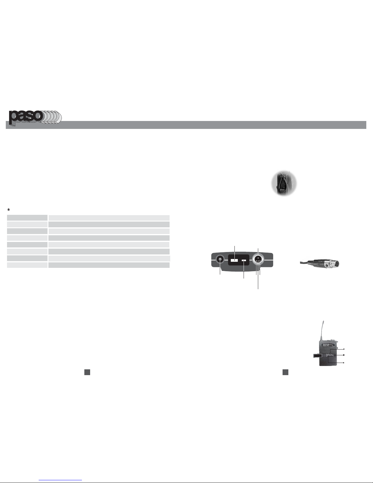
Depending on customer requirements, Lavalier / Headset microphone or
instrument inputs can be connected to the transmitter via the audio input
connector.Useris freeto choose the various input sources but is advisedtotake
note that connector used must be compatible to each other. The pin
configurationsforthe miniXLR connectoris in Fig.8.
INSTALLATION OF LAVALIER / HEADSET
MICROPHONES OR INSTRUMENT INPUTS
ANTENNA
GT IN
LED INDICATOR
MT IN
GND
PHANTOM POWER
POWER
SWITCH
POWER
OFF ON
1
2
3
4
Fig.8
PROFESSIONAL AUDIO & SOUND
®
RDU216
16
MW165U
MW163U
½ 19”
Channel Selection and Gain Adjust
Channel selector and gain adjust are hidden in the designated cover in the front as
shown in picture.
To make channel selection and gain adjust, press the designated cover and flip
it open as shown.
Channel selection can be made by
rotating the selector with the frequency
adjust driver. Gain adjust for Lavalier
and Headset microphones can be done
by adjusting the MT switch, whereas
GT switch is for the gain adjust of
electric Guitar and other high impedance
line level inputs.
MT
Channel
GT
MW163U
Selector
PROFESSIONALAUDIO&SOUND
®
1PCS
1PCS
2PCS
1PCS
1PCS
1PCS
1COPY
MW163U
Optional Accessories
Headset microphone w
19” Rack mountwithdual antenna mountingplate. PRK216
Collar microphone forMW163U MC63
ith aerobic sweatguardfor MW163U MHS63
Aerobic waist pouchforMW163U WP163

2
Fig.2
BELT-PACK TRANSMITTER (MW163U)
MW163U uses one 9V battery, To install or remove the battery , press the
release button at the side edge of transmitter to open or close the cover as in
(Fig.2) To switch on the unit, put the switch to "ON" position. The red LED
indicator will light briefly indicating that battery is fresh. When the RED LED
light is steady, it indicates that battery is weak, and that a replacement is
necessary.
INSTALLATION OF BATTERIES
9
PROFESSIONAL AUDIO & SOUND
®
MW163U
PR
O
F
ES
SIO
N
A
L
A
U
D
IO
&
SO
UN
D
®
PROFESSIONALAUDIO&SOUND
®
BEFORE OPERATING THE RDU216 W/MW165U or MW163U, BE
SURE YOU FULLY UNDERSTAND ALL INSTRUCTIONS AND
FEATURES OF THE UNIT.
1) Read these instructions carefully.
2) Keep these instructions.
3) Heed all warnings.
4) Follow all instructions.
5) DO NOT use this apparatus near water.
6) Clean ONLY with a damp cloth.
7) DO NOT block any of the ventilation openings. Install in
accordance with the instructions provided.
8) DO NOT install near any heat sources such as radiators,
stoves, or other apparatus that produce heat.
9) DO NOT mount the RDU216 into a container or a closed
unventilated closet while operating.
11) Use only the attachments and accessories specified in this
manual.
12) Unplug this apparatus during lightning storms or when unused
for long periods of time.
13) Refer all servicing to qualified service personnel. Servicing is
required when the apparatus has been damaged in any way,
such as power supply cord or plug is damaged, liquid has been
spilled or objects have fallen into the apparatus, the apparatus
has been exposed to rain or moisture, does not operate normally,
or has been dropped.
14) DO NOT install accessories unless the power cord is removed
from the AC wall outlet and power switch is off.
TO REDUCE THE RISK OF FIRE OR ELECTRIC SHOCK DO NOT EXPOSE
THIS APPLIANCE TO WATER, RAIN OR MOISTURE
IMPORTANT SAFETY INSTRUCTIONS
READ BEFORE OPERATING
MW163U
MW163U

Now switch on the transmitter (please refer to transmitter operating instructions).
The RF indicator will light up when the correct channel is selected, indicating that
the radio signal transmitted has been received.
Use RF test button to test if there is interference around. If there is interference
around, the RF signal level LED will light up. The receiver is indicating to switch to
another frequency.
When an audio signal into the microphone, the audio indicator will flash to show
the strength of the audio level.
OPERATING INSTRUCTIONS
Before switching on the receiver, make sure that the units antenna system is
attached and placed at 45 degree angles opposite of each other (Polarization
Diversity) and that the unit is positioned in an unobstructed location.
3
8
The MW165U has a module design. To change or replace a capsule, Open the grill to pull out
and plug in thecapsuleas shown in the following figure.
CHANGING OF CAPSULE
The MW165U has a sensitivity switch, For close singing or normal speech put the switch to
the N (normal) position.For tripod-mount speech, putthe switch to theH (high) position.
SENS
H
N
Low Sensitivity High Sensitivity
SENS
H
N
OPERATING INSTRUCTIONS
SENSITIVITY SWITCH
MW165U
PROFESSIONAL AUDIO & SOUND
®
FRONT AND REAR PANEL CONTROL
1.
Power switch
2. Power on indicator
3. RF signal indicator
4. Diversity indicator
5. AF signal indicator
6.
Channel selector
7.
RF test button
8. Volume control
9. Antenna B socket
10. XLR ( balanced ) audio output
11. Unbalanced audio output
12. Squelch ( SQ ) control.
13. D C IN jack
14.
Antenna A socket
ON
RFSIGNAL LEVEL AFSIGNAL LEVELDIVERSITY RF-TEST CHANNEL VOLUME
MIN MAX
A
B
1
3
5
7
9
15
13
11
PLLTRUE DIVERSITYRECEIVER
RDU216
POWER
1 2 3 4 5 6 7 8
9
11 12 13 1410
RDU216
PROFESSIONALAUDIO& SOUND
®
Before operation, please check and make sure that transmitter & receiver are of
matching channels.
To switch on the microphone, put the switch to "ON" position. The red LED indicator will
light briefly indicating that battery is fresh. When the RED LED light is steady, it indicates
that battery is weak, thus a replacement is necessary.
For best results, an alkaline battery is recommended. Please remove the battery if the
transmitter is not to be used for a longer period.
When necessary, the MW165U microphone capsule can be replaced by pulling out and
plugging in the new one.
For close singing or speaking, put the sensitivity switch to N (Normal) and for mic stand
applications or when the speaker stands away , put the sensitivity switch to
H (High). Be careful to put back the sensitivity switch to N for close singing as H (High)
sensitivity for close vocal applications may cause distortion.
When holding the handheld microphone, please do not hold the antenna end of the unit
for it will severely affect the efficiency of the transmission range.
at a distance

Press
RECEIVER INSTALLATION
Audio output connection
There are two audio outputs on the back of the Diversity RDU216
receiver. Mic-level balanced and Line-level unbalanced. Use shielded
audio cable for the connection between the receiver and the mixer. If
the mixer / amp is a 1/4" phone jack, connect a cable from the 1/4"
unbalanced audio output from the receiver to the mixer / amp. If the
mixer has an XLR input, connect a cable from the balanced XLR audio
output from the receiver to the mixer input.
For best operation, the receiver should be at
least 1m above the ground and at least 1 m
away from a wall or metal surface to minimize
reflections. The transmitter should also be at
least 1 m away from a wall or metal surface to
minimize reflections. The transmitter should
also be at least 1 m away from the receiver, as
shown in Fig. 5
Keep receiver antennas away from noise
sources.
True Diversity:
True Diversity utilizes two receiver channels to
avoid “dropout” or loss of RF signals created
by waves propagating in a reflective, or
multipath environment. The RDU216
incorporates an advanced microprocessor that
selects the audio from the antenna and
receiver channel with the best RF signal.
4
Fig.5
7
MW165U uses a9V battery for power. To changeor replace the battery. Please removethe antenna cap first, then
press at thebottom of battery compartmentto release the cover asshown in the figure below.
BATTERIES
CAUTION
The positive( +)pole of batterymustface downward. Manybatteriesare known tohave leakageproblemof
conductive andcorrosiveliquid. Pleaseobservethe rule toremove the batteriesifthey arenotto beusedfor
a periodof afew days.
1. Capsule with metal grill
2.
3.
4. Power on / off switch
5.
Battery indicator
Sensitivity switch
Battery compartment
6. Antenna Cap
2 314 5 6
HAND-HELD MICROPHONE MW165U
PROFESSIONAL AUDIO & SOUND
®

RDU216 are 1/2 19" casings and are specially designed (optional) 19" rack mount adapters
(PRK216) areavailable for yourinstallation purposes. Installationinstructions are asFig. 10.
5
Fig.10
RF INTERFERENCE
used.
RF Interference
If you encounter receiving interference (from other than an
operating TV station), often it can be overcome by adjusting the
receiver's squelch control, as described below.
Please note that wireless frequencies are shared with other radio
services. According to FCC regulations, wireless microphone
operations are unprotected from interference from other licensed
operations in the band.
Receiver Squelch Control
The squelch control on the back panel of the receiver is preset at
the factory, but can be adjusted if you must use the system in a high
RF interference area. If there is audio output from the receiver
when your transmitter is OFF, adjust the squelch control so the
system will receive the signal from your transmitter but squelch or
eliminate the unwanted background RF noise. This adjustment can
cause a reduction in usable range of the wireless transmitter, so set
the control to the lowest position which reliably mutes the unwanted
RF signal.
RF Test Function
The most unique feature of this unit is the RF test manual scanner
feature. By pressing the RF test button, the user is free to scan
through all the channels to look for a clean channel before
operation. When the RF test button is pressed, a lighted RF
indicator means that the selected channel is occupied and
interference will occur when
RACK MOUNTING
TIPS TO OBTAIN THE BEST RESULTS
FOR A WIRELESS MICROPHONE SYSTEM
6
PROFESSIONAL AUDIO & SOUND
®
If an external antenna is used a low loss 50-ohm RF shielded cable must be
used and the length of the cable should not exceed 3 meters.
The receiver antenna should be kept away from any metal surface.
If the volume control of the receiver is set too high, it may over-drive the input,
causing distortion. Conversely, if the receiver output is set too low, the overall
signal to noise ratio of the system may be reduced. Adjust the output level of
the receiver such that highest sound pressure level going into the microphone
causes no input overload in the mixer, and yet permits the mixer level controls
to operate in their normal range (not too high or too low). This provides the
optimum signal to noise for the entire system.
Before inserting the batteries, please make sure that they are inserted
according to the correct polarity.
Before system operation, please make sure that the corresponding receiver
MUST have the same channel number as the transmitter.
Before making any channel change, please switch off the power supply. The
synthesized program works in such a way that a change of channel will only
take place after a power off and on action. Otherwise, the previously selected
frequency will stay unchanged.
After making a channel change, please make sure that the corresponding
change is made on the matching receiver also. To be exact, changes MUST be
made at both the transmitter and receiver.
Use only brand new alkaline batteries. Do not use " general purpose "
batteries. When batteries are weak, replace the batteries altogether at the same
time. Do not mix and use new and old batteries together.
Position the receiver such that it has the least possible obstructions between it
and the transmitter. Line of sight is best!
The transmitter and the receiver should be as close as possible but not less
than 1 meter.
A receiver cannot receive signals from two or more transmitters simultaneously.
Turn the transmitter off when it is not in use. Remove the batteries if the
transmitter is not to be used for a period of time.
 Loading...