

Paso Sound Products DMS4121B, DMS4161B, DMS4241B, DMS4361B Installation Manual And Operating Instructions
Series DMS
PROFESSIONAL AUDIO & SOUND
®
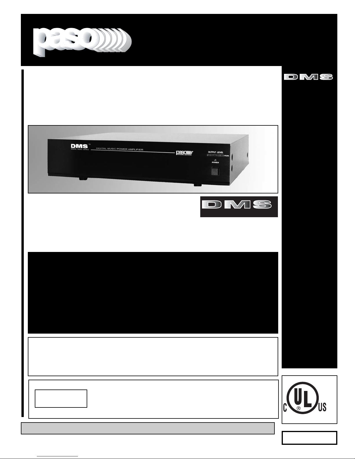
DDiiggiittaall MMuussiicc AAmmpplliiffiieerrss
Power Amplifiers
Innovation through technology since 1931
Manual
OOMM 116644
Installation Manual
and Operating Instructions
4 Channel - 3 Zone - Dual VOX -
MOH - Vox Relay - Module Port
TTOO RREEDDUUCCEE TTHHEE RRIISSKK OOFF FFIIRREE OORR EELLEECCTTRRIICC
SSHHOOCCKK DDOO NNOOTT EEXXPPOOSSEE TTHHIISS AAPPPPLLIIAANNCCEE TTOO
WWAATTEERR,, RRAAIINN OORR MMOOIISSTTUURRE
E
CAUTION !
REV. 1.0
IMPORTANT NOTE:
THIS OPERATING MANUAL IS PROVIDED AS AN INSTALLATION AND
AS AN OPERATING AID. PASO SOUND PRODUCTS, INC. DOES NOT ASSUME ANY
RESPONSIBILITY AS TO ITS ACCURACY AND SHALL NOT BE LIABLE IN TORT OR CONTRACT FOR ANY DIRECT CONSEQUENTIAL OR INCIDENTAL LOSS OR DAMAGE ARISING
FROM THE INSTALLATION, USE OR INABILITY TO USE THIS PRODUCT.
DDMMSS44112211BB -- 112200 WWaatttt RRMMSS
DDMMSS44116611BB -- 116600 WWaatttt RRMMSS
DDMMSS44224411BB -- 224400 WWaatttt RRMMSS
DDMMSS44336611BB -- 336600 WWaatttt RRMMSS
TM
DIGITAL MUSIC SERIES
TM
DIGITAL MUSIC SERIES
© copyright Paso Sound Products, Inc. 2005 Specifications are subject to change without notice
LISTED
COMMERCIAL
AUDIO
EQUIPMENT
30TJ

PROFESSIONAL AUDIO & SOUND
®
M
DESCRIPTION AND APPLICATIONS SPECIFICATIONS
PAGE 2
DMS4121/4161/4241/4361
Power Output:
DMS4121B
DMS4161B
DMS4241B
DMS4361B
Distortion:
Frequency Response:
Inputs:
Input 1
Input 2
Input 3
Input 4
Sensitivity & Z:
Input 1
Input 2
Input 3
Input 4
Attenuator:
Phantom Power:
Hum & Noise:
Telephone Paging Input:
Accessory Port:
EQ LINK:
Line Outputs:
Inputs/Outputs:
Subwoofer Outputs:
Subwoofer Output Level:
Music on Hold Output:
Zone 2 Output:
Zone 3 Output:
Main Output Impedance:
Controls:
Rear Panel:
Remote Volume Controls:
MOH Source Selection:
Zone 2 and 3 Source
Selection:
VOX:
VOX BUSS:
MUTE BUSS:
MUTE DELAY:
Unmuting:
Power Supply Output:
Auto VOX Relay:
Rack Mounting:
Vertical Rack Profile:
Internal Cooling Fan:
Power Requirement:
Power Consumption:
A
C Accessory Outlet:
Terminations:
Housing Finish:
Output Power Indicator:
Dimensions:
Net Weight:
DMS4121B
DMS4161B
DMS4241B
DMS4361B
UNPACKING
Immediately upon receipt of the amplifier, inspect the unit
and shipping container for indications of improper handling
or in transit damage. The equipment was carefully inspect-
ed and tested before leaving the factory. Notify the
Transportation Company immediately if any damage is
found. ONLY THE CONSIGNEE CAN FILE A CLAIM WITH
THE CARRIER FOR DAMAGE DURING SHIPMENT. Be
sure to save the carton and packing material as evidence of
damage for the shipper inspection. DO NOT SHIP the unit
back to the factory unless authorized by the factory.
IN TRANSIT DAMAGES ARE NOT COVERED BY THE
PASO WARRANTY.
120 Watt RMS
160 Watt RMS
240 Watt RMS
360 Watt RMS
Less than 0.5% THD
20 - 20,000 Hz ± 1 db
Microphone 1 Balanced
Telephone Interface - Transformer Balanced
AUX
(Stereo Summing)
Module Port
Mic 1
= 1.5 Mv - 250 ohm
Te l
=100 Mv - 600 ohm - Transformer Balanced
AUX = 100 Mv - 47K ohm
Module
= 1 V - 47K ohm
Variable (rear panel control)
On MIC Input by internal jumper (18 V)
Mic
-70 db,
Aux
-75 db
600 ohm Transformer balanced
Accepts Standard Module
Preamp out, Power Amp in with EQ Link Switch
Line Out 600 ohm - 1.5 V loaded
MIX BUSS
Pre-EQ and Post-EQ Outputs
1 Volt
600 ohm-1 Volt Transformer Balanced
1 Watt-8 ohm with Control
1 Watt-8 ohm with Control
8 ohm, 25 Volt and 70 Volt line
MIC Input Volume - PHONE Level - AUX Input
Volume - Module Volume - AUX Input Attenuator MOH/ZONE 1 Level Control - ZONE 2 Level Control
- VOX 1/VOX 2 Sensitivity - VOX TIME Delay
AUX Input Volume and Master Volume
AUX - MODULE by internal jumper
AUX - MODULE by internal jumper
Voice Activated Muting
Available on all 4 Inputs by internal jumpers
Available on all 4 Inputs by internal jumpers
Adjustable from 3 Sec to 30 Sec (rear panel control)
MUTES/UNMUTES MIC Input only
24 V DC - 250 mA Regulated
NO/NC Contacts - VOX activated-Rating = 7 A
Optional19” Rack Mounting Kit
2-U of Vertical Rack Space
3” Thermally Controlled
117 Volt, 50-60 Hz
DMS4121B = AC = 850 VA - DMS4161B = AC =
970 VA - DMS4241B = 1200 VA - DMS4361B =
1500VA Max.
500 W Max. Unswitched
Screw Terminals, RCA Jacks
Black
Multi-color LED
(front panel)
DMS4121B - DMS4161B - DMS4241B = 19” W., 12”
D., 4” H. with feet
(482X305X102 mm)
3.5” H
(89 mm)
. less feet
DMS4361B = 19” W., 15” D., 4” H. with feet
(482X381X102 mm)
3.5” H
(89 mm)
. less feet
22 Lbs
(11 Kg)
25 Lbs
(11.4 Kg)
26
(11.8 Kg)
33 Lbs
(15 Kg)
High Performance - High Reliability Design
Wide Frequency Response - Very Low Distortion
4 Channel Inputs - 3 Zone Outputs
Balanced Microphone Input
Phantom Power on MIC Input
600 ohm Transformer Balanced
Telephone Paging Input
Telephone Input Level Control
Auxiliary Input with Stereo Summing
Auxiliary Input Attenuator
Independent Input Controls
Addressable VOX Buss
Voice Activated Muting
VOX Variable Time Delay Function
Addressable MUTE Buss
Direct Muting or Unmuting
Rear Panel Port accepts Standard Module
Independent Module Level Control
External EQ Link
600 ohm and 8 ohm 1 Watt MOH Amplifier
MOH Amplifier Source Selector
Zone 2-3, 1 Watt - 8 ohm Output with Control
MIX Buss and 600 ohm Line Output
NO/NC VOX Operated Relay
AUX1 and Master Remote Volume Controls
24 V DC 250 mA Regulated Power Supply Output
8 ohm, 25 Volt & 70 Volt Output
Pre-EQ Subwoofer Output
Post-EQ Subwoofer Output
19” Rack Mounting Ready
Low profile - 2-Units of Vertical Rack space
UL 6500 Listed (US - CANADA)
DIGITAL MUSIC AMPLIFIERS
T
DIGITAL MUSIC SERIES
© copyright Paso Sound Products, Inc. 2005 Specifications are subject to change without notice
PROFESSIONAL AUDIO & SOUND
®
M
PAGE 3
SPECIFICATIONS ARE SUBJECT TO CHANGE WITHOUT NOTICEDMS4121/4161/4241/4361
READ BEFORE OPERATING READ BEFORE OPERATING
BEFORE OPERATING THE AMPLIFIER, BE SURE YOU
FULLY UNDERSTAND ALL INSTRUCTIONS AND FEATURES OF THE UNIT.
1)
Read these instructions carefully.
2)
Keep these instructions.
3)
Heed all Warnings.
4)
Follow all instructions.
5) DO NOT use this apparatus near water.
6) Clean ONLY with a damp cloth.
7) DO NOT block any of the ventilation openings.
Install in accordance with the instructions provided.
8) DO NOT install near any heat sources such as
radiators, stoves, or other apparatus (including amplifiers) that produce heat.
9) DO NOT mount amplifier into a container or a
closed unventilated closet while operating.
10) DO NOT place any object or accessory equipment
such as Tuners, Mixers, Cassette Decks, etc. on top of
the amplifier. Obstructing or closing the cabinet ventilation openings may cause overheating.
11) DO NOT defeat the safety purpose of the polarized or grounding type plug. A polarized plug has two
blades with one wider than the other. A grounding type
plug has two blades and a third grounding prong. The
wide blade and or the third prong is provided for your
safety. When the provided plug does not fit into your
outlet, consult an electrician for replacement of the
obsolete outlet.
12) Use only the attachments and accessories specified in this manual.
13) If a cart is used, use caution when moving the
cart/apparatus combination to avoid injury from tipover.
14) Unplug this apparatus during lighting storms or
when unused for long periods of time.
15) Refer all servicing to qualified service personnel.
Servicing is required when the apparatus has been
damaged in any way, such as power supply cord or
plug is damaged, liquid has been spilled or objects
have fallen into the apparatus, the apparatus has been
exposed to rain or moisture, does not operate normally, or has been dropped.
16) DO NOT replace fuses unless power cord is
removed from the AC wall outlet.
17) DO NOT install accessories unless the power
cord is removed from the AC wall outlet.
TO REDUCE THE RISK OF FIRE OR
ELECTRIC SHOCK DO NOT EXPOSE
THIS APPLIANCE TO WATER, RAIN OR
MOISTURE
IMPORTANT SAFETY INSTRUCTIONS
DIGITAL MUSIC AMPLIFIERS
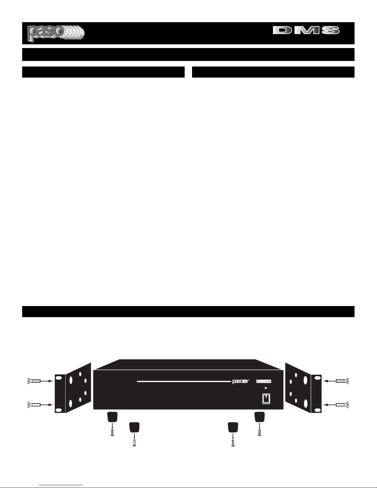
RACK MOUNTING
A) Procure the optional accessory Rack Mount Kit Model 27/3501.
B) Turn amplifier up side down and remove the four rubber feet by unscrewing the four holding screws.
C) Remove two screws on each side of the amplifier holding the amplifier cover.
D) Install the rack kit brackets by using the self-tapping screws provided.
Fig. 3 - Rack Kit Mounting
T
DIGITAL MUSIC SERIES
DMS
DIGITAL MUSIC SERIES
TM
DIGITAL MUSIC AMPLIFIER
PROFESSIONAL AUDIO & SOUND
OUTPUT LEVEL
POWER
PEAK
O
 Loading...