


© copyright Paso Sound Products, Inc. 2004 Specifications are subject to change without notice
Innovation through technology since 1931
Installation Manual
and Operating Instructions
4 Channel - 2 Zone - VOX - Mute -
MOH - Phone Interface
TTOO RREEDDUUCCEE TTHHEE RRIISSKK OOFF FFIIRREE OORR EELLEECCTTRRIICC
SSHHOOCCKK DDOO NNOOTT EEXXPPOOSSEE TTHHIISS AAPPPPLLIIAANNCCEE TTOO
WWAATTEERR,, RRAAIINN OORR MMOOIISSTTUURRE
E
CAUTION !
REV. 1.0
IMPORTANT NOTE:
THIS OPERATING MANUAL IS PROVIDED AS AN INSTALLATION AND
AS AN OPERATING AID. PASO SOUND PRODUCTS, INC. DOES NOT ASSUME ANY
RESPONSIBILITY AS TO ITS ACCURACY AND SHALL NOT BE LIABLE IN TORT OR CONTRACT FOR ANY DIRECT CONSEQUENTIAL OR INCIDENTAL LOSS OR DAMAGE ARISING
FROM THE INSTALLATION, USE OR INABILITY TO USE THIS PRODUCT.
DDMMAA 33006600 -- 6600 WWaatttt RRMMSS
DDMMAA 33112200 -- 112200 WWaatttt RRMMSS
®
Series DMA
Integrated Amplifiers
Manual
OOMM 117711
DDiiggiittaall MMuussiicc AAmmpplliiffiieerrss
PROFESSIONAL AUDIO & SOUND
LISTED
COMMERCIAL
AUDIO
EQUIPMENT
30TJ

DESCRIPTION AND APPLICATIONS SPECIFICATIONS
PAGE 2
© copyright Paso Sound Products, Inc. 2004 Specifications are subject to change without notice
DMA3060/3120
UNPACKING
Immediately upon receipt of the amplifier, inspect the unit
and shipping container for indications of improper handling
or in transit damage. The equipment was carefully inspected and tested before leaving the factory. Notify the
Transportation Company immediately if any damage is
found. ONLY THE CONSIGNEE CAN FILE A CLAIM WITH
THE CARRIER FOR DAMAGE DURING SHIPMENT. Be
sure to save the carton and packing material as evidence of
damage for the shipper inspection. DO NOT SHIP the unit
back to the factory unless authorized by the factory.
IN TRANSIT DAMAGES ARE NOT COVERED BY THE
PASO WARRANTY.
❑❑
High Performance - High Reliability Design
❑❑
Wide Frequency Response - Very Low Distortion
❑❑
5 Channel Inputs - 2 Zone Outputs
❑❑
Up to 3 Balanced Microphone Inputs
❑❑
Phantom Power on all MIC Inputs
❑❑
MIC 2/AUX 1 and MIC 3/AUX 2 Inputs
With Stereo Summing
❑❑
AUX1 and AUX2 Inputs Attenuator
❑❑
600 ohm Transformer Balanced
Telephone Paging Input
❑❑
MIX Buss and 600 ohm Line Output
❑❑
Independent Input Controls
❑❑
AUX1 Remote Volume Controls
❑❑
External EQ Link
❑❑
Tone by-pass and EQ Link switches
❑❑
Addressable VOX Buss
Voice Activated Muting
❑❑
VOX Variable Time Delay Function
❑❑
Addressable MUTE Buss
❑❑
Direct Muting and Unmuting
❑❑
600 ohm and 8 ohm 2 Watt Max.
Music on Hold Amplifier
❑❑
MOH Amplifier Source Selector
❑❑
Zone 2, 2 Watt - 8 ohm Output
with Separate Control
❑❑
24 V DC 250 mA Regulated Power Supply Output
❑❑
8 ohm, 25 Volt & 70 Volt Output
❑❑
Optional 19” Rack Mounting with Kit
❑❑
Low profile - 2-Unit of Vertical Rack space
❑❑
UL 6500 Listed (US - CANADA)
PROFESSIONAL AUDIO & SOUND
®
DIGITAL MUSIC AMPLIFIERS
POWER OUTPUT: DMA3060 60 Watt RMS
DMA3120 120 Watt RMS
Distortion: 0.01% THD at 1 kHz rated power
Frequency Response: 20 hz - 30 Khz ± 2 dB
Inputs:
Input 1 MIC Electronically Balanced,
Transformer Balanced with MT250 (optional)
Input 2 Telephone Transformer Balanced
Input 3 MIC Electronically Balanced - AUX 1 (Stereo Sum.)
Input 4 MIC Electronically Balanced - AUX 2 (Stereo Sum.)
Input 5 Module Port
Sensitivity & Z:
Input 1
Mic 1
= 1.5 Mv - 250 ohm
Input 2
Te l
=100 Mv - 600 ohm - Transformer Balanced
Input 3
Mic 3
= 1.5 Mv - 250 ohm - AUX 1 = 100 Mv - 47K ohm
Input 4
Mic 4
= 1.5 Mv - 250 ohm - AUX 2 = 100 Mv - 47K ohm
Input Attenuator: AUX 1 and AUX 2
Phantom Power: All Microphone Inputs by internal jumper (18 V)
Hum & Noise:
Mic
-70 db,
Aux
-75 db 600 ohm Transformer balanced
Telephone Paging Input: 600 ohm Transformer Balanced
EQ LINK: Preamp. out, Power Amp in with EQ Link Switch
Line Output: Line Out 600 ohm - 1.5 V loaded
Inputs/Outputs: MIX BUSS
Zone 1 Output: 2 Watt Max. - 8 ohm with Control
Music on Hold Output: 600 ohm-1 Volt Transformer Balanced
Zone 2 Output: 2 Watt Max. - 8 ohm with Control
Main Output Impedance: 8 ohm, 25 Volt and 70 Volt line
Controls:
Front Panel: Input 1 Volume, Input 2 Volume, Input 3 Volume,
Input 4 Volume, Module Volume, Bass and Treble
Rear Panel: AUX 1 Attenuator - AUX 2 Attenuator, VOX1 Sensitivity,
VOX2 Sensitivity, MOH/ZONE 1 Level Control - ZONE 2
Level Control - VOX Sensitivity - MUTE Delay
Tone Controls: Bass and Treble ± 10 dB at 100 hZ and 10 KHz
Tone By-Pass: On - Off Switch Rear Panel
Remote Volume Control: INPUT 3 - AUX 1 Input Volume
MOH Source Selecti: AUX 1 and AUX 2
Zone 2 Source Select: AUX 1 and AUX 2
VOX BUSS: Available on all Inputs by internal Jumper
MUTE BUSS: Available on all Inputs by internal Jumper
MUTE DELAY: Adjustable from 3 Sec to 60 Sec (rear panel control)
Direct Muting: M1, M2 External Contact Closure
Unmuting: MUTES/UNMUTES MIC 1 only
Power Supply Output: 24 V DC - 250 mA Regulated
Rack Mounting: Optional 19” Rack Kit
Internal Cooling Fan: Thermally Controlled
Protection: Power Surge, Overload and Thermal Protection
Power Requirement: 117 Volt, 50-60 hZ
Power Consumption: DMA3060 = 670VA - DMA3120 = 850VA Max.
AC Accessory Outlet: 117 v - 500 W Max. Unswitched
Terminations: Screw Terminals, RCA Jacks
Housing Finish: Black
Output Power Indicator: Multi-color LED Signal and Clip
Dimensions: 10.75” W., 11” D., 4” H. with feet
(274X280X102 mm)
3.5” H
(89 mm)
. less feet
Net Weight: DMA3060 = 16 Lbs
(7.3 Kg)
DMA3120 = 19 Lbs
(8.7 Kg)
PAGE 3
SPECIFICATIONS ARE SUBJECT TO CHANGE WITHOUT NOTICEDMA3060/3120
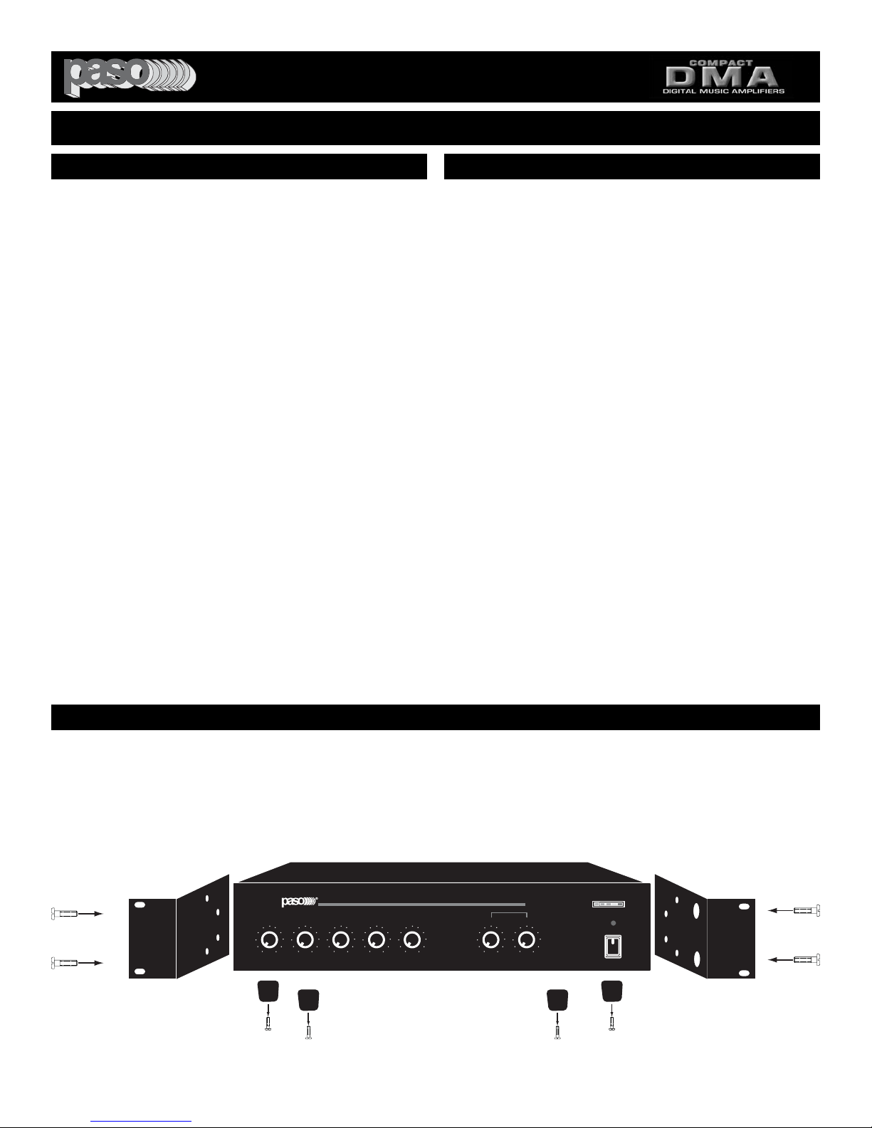
RACK MOUNTING
A) Procure the optional accessory Rack Mount Kit Model 27/3500.
B) Turn amplifier up side down and remove the four rubber feet by unscrewing the four holding screws.
C) Remove the bottom front screws on each side of the amplifier holding the amplifier cover.
D) Install the rack kit brackets by using the self-tapping screws provided.
Fig. 3 - Rack Kit Mounting
READ BEFORE OPERATING READ BEFORE OPERATING
BEFORE OPERATING THE AMPLIFIER, BE SURE YOU
FULLY UNDERSTAND ALL INSTRUCTIONS AND FEATURES OF THE UNIT.
1)
Read these instructions carefully.
2)
Keep these instructions.
3)
Heed all Warnings.
4)
Follow all instructions.
5) DO NOT use this apparatus near water.
6) Clean ONLY with a damp cloth.
7) DO NOT block any of the ventilation openings.
Install in accordance with the instructions provided.
8) DO NOT install near any heat sources such as
radiators, stoves, or other apparatus (including amplifiers) that produce heat.
9) DO NOT mount amplifier into a container or a
closed unventilated closet while operating.
10) DO NOT place any object or accessory equipment
such as Tuners, Mixers, Cassette Decks, etc. on top of
the amplifier. Obstructing or closing the cabinet ventilation openings may cause overheating.
11) DO NOT defeat the safety purpose of the polarized or grounding type plug. A polarized plug has two
blades with one wider than the other. A grounding type
plug has two blades and a third grounding prong. The
wide blade and or the third prong is provided for your
safety. When the provided plug does not fit into your
outlet, consult an electrician for replacement of the
obsolete outlet.
12) Use only the attachments and accessories specified in this manual.
13) If a cart is used, use caution when moving the
cart/apparatus combination to avoid injury from tipover.
14) Unplug this apparatus during lighting storms or
when unused for long periods of time.
15) Refer all servicing to qualified service personnel.
Servicing is required when the apparatus has been
damaged in any way, such as power supply cord or
plug is damaged, liquid has been spilled or objects
have fallen into the apparatus, the apparatus has been
exposed to rain or moisture, does not operate normally, or has been dropped.
16) DO NOT replace fuses unless power cord is
removed from the AC wall outlet.
17) DO NOT install accessories unless the power
cord is removed from the AC wall outlet.
TO REDUCE THE RISK OF FIRE OR
ELECTRIC SHOCK DO NOT EXPOSE
THIS APPLIANCE TO WATER, RAIN OR
MOISTURE
IMPORTANT SAFETY INSTRUCTIONS
PROFESSIONAL AUDIO & SOUND
®
DIGITAL MUSIC AMPLIFIERS
PROFESSIONAL AUDIO & SOUND
100 100 100 100 100 +10-10 +10-10
INPUT 1/MIC
DIGITAL MUSIC AMPLIFIER
INPUT 3/AUX 1 INPUT 4/AUX 2 BASS TREBLE
TEL
MODULE
DMA
DIGITAL MUSIC SERIES
00
OUTPUT LEVEL
TM
PEAK
POWER
O

PAGE 4
SPECIFICATIONS ARE SUBJECT TO CHANGE WITHOUT NOTICE DMA3060/3120
1) INPUT 1 Volume Control
2) TEL INPUT Volume Control
3) INPUT 3/AUX 1 Volume Control
4) INPUT 4/AUX 2 Volume Control
5) Module Volume Control
6) BASS Control
7) TREBLE Control
8) On-Off Power Switch
9) Output Level Indicator
Fig. 4 - FRONT PANEL CONTROLS
PROFESSIONAL AUDIO & SOUND
®
DIGITAL MUSIC AMPLIFIERS
PEAK
9
OUTPUT LEVEL
TM
DIGITAL MUSIC SERIES
DMA
DIGITAL MUSIC AMPLIFIER
POWER
00
O
PROFESSIONAL AUDIO & SOUND
100 100 100 100 100 +10-10 +10-10
MODULE
INPUT 3/AUX 1 INPUT 4/AUX 2 BASS TREBLE
TEL
INPUT 1/MIC
2 3 4 5 6 7 8
1
PAGE 5
SPECIFICATIONS ARE SUBJECT TO CHANGE WITHOUT NOTICEDMA3060/3120
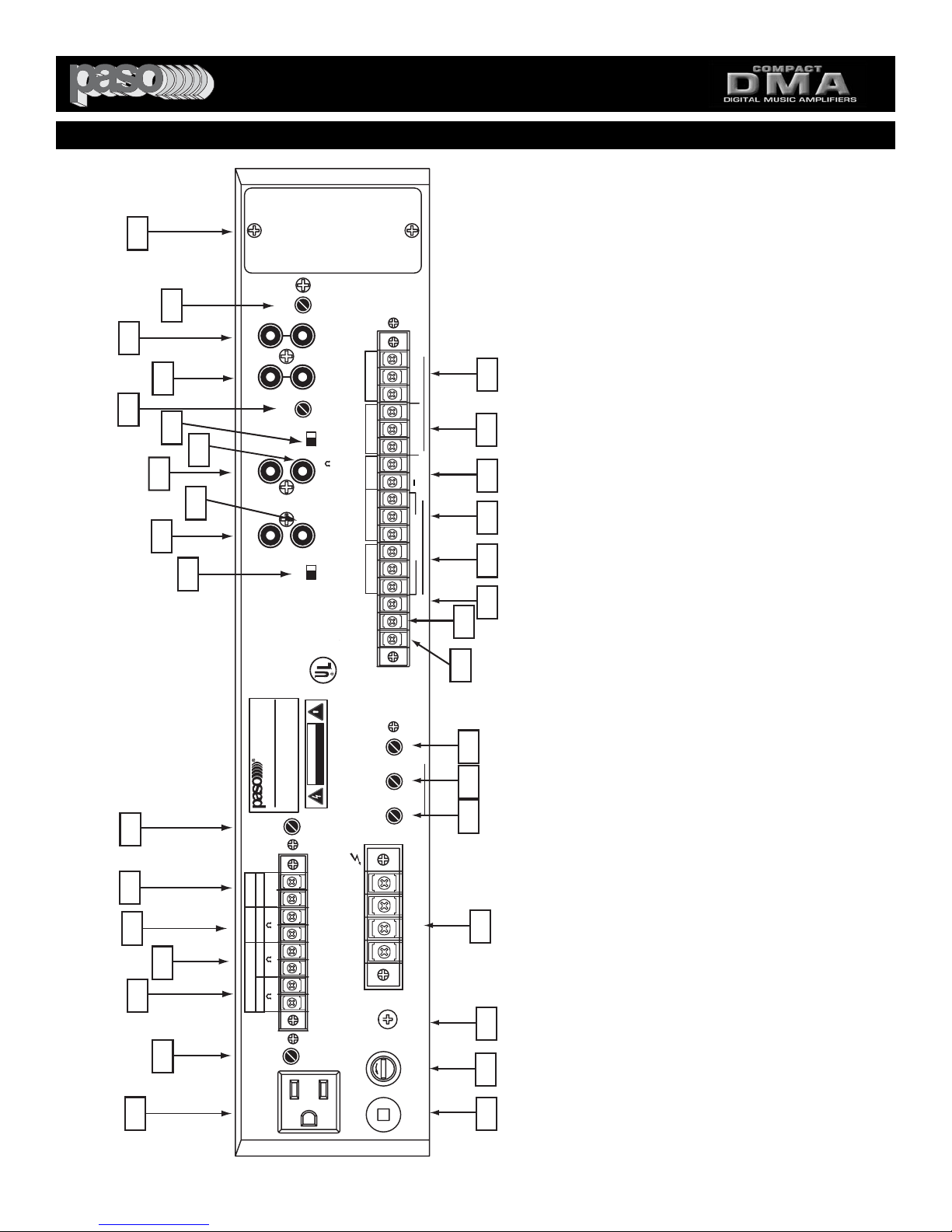
Fig. 5- REAR PANEL INPUTS - OUTPUTS - CONTROLS
1) Unswitched AC Auxiliary Socket
2) MOH - ZONE 1 Output Level Control
3) 1 MOH - 600 ohm, 1 Volt Output
4) ZONE 1 - 8 ohm Output
5) ZONE 2 - 8 ohm Output
6) 24 Volt DC Regulated Power Supply Output
7) ZONE 2 Output Level Control
8) EQ LINK Switch
9) EQ LINK - PREAMP. OUT
10) EQ LINK - POWER AMP IN
11) MIX BUSS
12) LINE OUT 600 Ohm
13) TONE BYPASS - ON/OFF SWITCH
14) INPUT 3 - AUX 1 Input Attenuator
15) INPUT 3 - AUX 1 - Stereo Summing Jacks
16) INPUT 4 - AUX 2 - Stereo Summing Jacks
17) INPUT 4 - AUX 2 Input Attenuator
18) Standard Module Port
19) TELEPHONE Paging Balanced Input 600 Ohm
20) INPUT 4 - AUX 2 Balanced Input
21) INPUT 3 Remote Volume Terminals
22) INPUT 3 _ AUX 2 Balanced Input
23) INPUT 1 - MIC 1 Balanced Input
24) MUTE 1 Terminal
25) MUTE 2 Terminal
26) MIC 1 UNMUTE Terminal
27) MUTE Time Delay Control
28) VOX 2 Sensitivity Control
29) VOX 1 Sensitivity Control
30) Speaker Output Terminals
31) Chassis Ground Screw
32) AC LIne Fuse
33) AC Power Cord
PROFESSIONAL AUDIO & SOUND
®
DIGITAL MUSIC AMPLIFIERS
16
14
7
18
17
(AUX2)
L
47kohm 100mV
INPUT-4(AUX2)
15
INPUT-3(AUX1)
47kohm 100mV
(AUX1)
13
12
MIX
11
BUSS
STANDARD
PORT ACCEPTS
INPUT 4
ATTENUATOR
R
ATTENUATOR
OFF
TONE
ON
LINE OUT
MODULE
SWITCH
MIC-AUX2
BY INTERNAL
BYPASS
AUX2
600
INPUT 3
CAUTION: REMOVE
POWER CORD FROM
TEL
G COM HOT
47Kohm 250 mV
INPUT 4 MIC-AUX2)
VOLUME
REMOTE
INSTALLING MODULE
AC OUTLET PRIOR TO
+
600 ohm 100mV
250ohm 1.5mV
BALANCED
19
20
21222324
10
INPUT 3
MIC-AUX1)
G COM HOT RVC RVC G COM HOT G COM HOT
9
PRE
OUT
8
BALANCED
TRANSFORMER
WITH OPTIONAL
INPUT 1 MAY BE
120 W RMS
DMA3120
DIGITAL MUSIC AMPLIFIER
PROFESSIONAL AUDIO & SOUND
POWER RATING
LEVEL
ZONE 2
IN
POWER
EQ LINK
EQ LINK
AUDIO
LISTED
EQUIPMENT
COMMERCIAL
MODEL MT250
850 VA
117V 60 HZ
DO NOT OPEN
CAUTION
RISK OF ELECTRIC SHOCK
SUPPLY VOLTAGE
POWER CONSUMPTION
INTERNAL
EXTERNAL
30TJ
CUS
MUST BE EARTHED
WARNING: THIS APPLIANCE
INPUT 1 (MIC)
MUTE 1
MUTE 2
UNMUTE
DELAY
MUTE-2
3~60 SEC
SENS
VOX-2
SENS
VOX-1
250ohm 1.5mV
Made by
PASO Taiwan
SER. NO.
26
25
272829
6
5
4
3
2
250 mA
24V DC
ZONE 2ZONE 1
2 W Max.
1 Volt 2 W Max.
+
-
0 8
0 8
0 600
LEVEL
ZONE 1
1 WATT
1 WATT
MOH OUT
1
CAUTION: TO REDUCE THE
RISK OF FIRE, REPLACE
ONLY WITH SAME TYPE
FUSE.
GROUND
SPEAKER OUTPUT
CLASS 2 WIRING ACCEPTABLE
SP
5A 250V
LINE FUSE
117V 60HZ
ATTENTION: POUR REDUIRLES RISQUES D' INCENDIE
OU DE CHOC ELECTRIQUE, NE PAS EXPOSER A LA PLUIE
OU L' HUMIDITE, NE PAS ENLEVER LE COUVERCLE. AUCUN
REGLAGE A L' INTERIEUR. POUR REPARATION CONSULTER
UNE PERSONNE QUALIFIEE
COM 8 25V 70V
BALANCED
CAUTION: TO REDUCE THE RISK OF FIRE OR
SHOCK DO NOT EXPOSE THIS APPLIANCE TO
RAIN OR MOISTURE. DO NOT REMOVE COVER.
THERE ARE NO USER SERVICEABLE PARTS
INSIDE. REFER SERVICING TO QUALIFIED
SERVICE PERSONNEL.
UNSWITCHED
117V 500W MAX
DMA3120 Rear Panel
30
Manual
31
32
33
PAGE 6
SPECIFICATIONS ARE SUBJECT TO CHANGE WITHOUT NOTICE
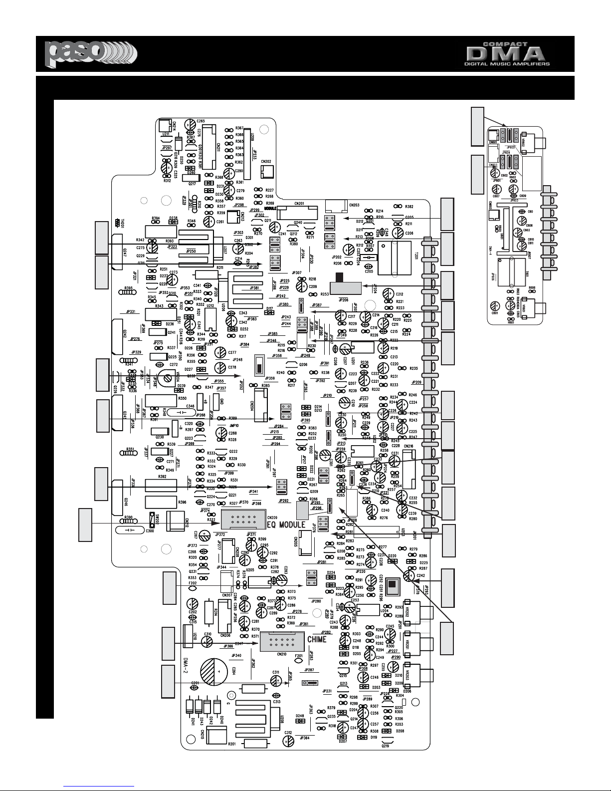
Fig. 6 - MAIN AND PREAMPLIFIER BOARD TOP VIEW
FUNCTION SWITCHES AND JUMPERS LOCATION
PROFESSIONAL AUDIO & SOUND
®
DIGITAL MUSIC AMPLIFIERS
DMA3060/3120
S310
JUMPER
MODULE
M1 M2 OFF
MUTE1 MUTE2
S309
JUMPER
MODULE
V1 V2 OFF
VOX1 VOX2
S303 (TEL)
M2
M1
S202(MIC4)
S301 (TEL)
AUX2
OFF
V2
V1
OFF
S201
MIC
MODULE INPUT
AUX2 AUX1
S310 (MOD)
S309 (MOD)
S311
M2
M1
OFF
V2
V1
OFF
PHANTOM
ON OFF
S302 INPUT4
V2
V1
OFF
ZONE 1
ZONE 2
S303
TEL PAGING
M1 M2 OFF
S301
V1 V2 OFF
TEL PAGING
S201
INPUT 4
AUX2 MIC
S202
ON OFF
PHANTOM
S302
INPUT4
V1 V2 OFF
JUMPER
SW606-604-605
AUX2 AUX1 MOD
AUX2 AUX1 MODULE
JUMPER
SW603-601-602
AUX2 AUX1 MOD
AUX2 AUX1 MODULE
JUMPER
MUTE1 MUTE2
JUMPER
VOX1 VOX2
SWITCH
AUX 2 MIC
DMA3120 - DMA-4
M.O.H. BOARD
MIC 4
POWER
JUMPER
VOX1 VOX2
SW605 MOD
SW602
SW604 AUX1 SW601
SW606 AUX2 SW603
ON OFF OFF ON
REAR PANEL
S311
INPUT
MODULE
AUX1 AUX2
SOURCE SWITCH
S304
INPUT4
JUMPER
M1 M2 OFF
MUTE1 MUTE2
S306
INPUT1
JUMPER
M1 M2 OFF
MUTE1 MUTE2
CN 209
OPTIONAL EQ
CARD SOCKET
S308
INPUT3
JUMPER
MUTE1 MUTE2
CN 210
SOCKET
OPTIONAL
CHIME CARD
S313
M2 M1
CHIME TRIGGER
M1 M2 OFF
S304 INPUT4
INPUT1
S306
M2
M1
OFF
ON OFF
AUX1 MIC
S305
INPUT1
S307
(INPUT3)
M2
M1
OFF
CHIME
S203(MIC3)
S314
V2
V1
OFF
S204
V2
V1
OFF
PHANTOM
S312(UNMUTE)
ON OFF
DIRECT
XFMER
(INPUT1)
S315
S203
POWER
ON OFF
PHANTOM
S314
INPUT 3
AUX1 MIC
AUX1 MIC
S305
INPUT1
V1 V2 OFF
VOX1 VOX2
S312
ON OFF
MIC1 UNMUTE
S307
INPUT3
V1 V2 OFF
VOX1 VOX2
S315
SWITCH
DIRECT XFMER
DIRECT - XFMER
S204
POWER
ON OFF
PHANTOM
MIC 3
JUMPER
AMPLIFIER REAR PANEL
JUMPER
JUMPER
INPUT1
MIC 1
M2
M1
OFF
PHANTOM
ON OFF
(MIC1)
SW308
INPUT3
M2 M1
S313
MAIN BOARD
DMA3120 - DMA-2

PAGE 7
SPECIFICATIONS ARE SUBJECT TO CHANGE WITHOUT NOTICE
DMA3060/3120
FUNCTION SWITCHES AND JUMPERS DEFAULT SETTING TABLE
S202 INPUT 4 (MIC 4) PHANTOM POWER ON - OFF OFF
S203 INPUT 3 (MIC 3) PHANTOM POWER ON - OFF OFF
S204 INPUT 1 (MIC 1) PHANTOM POWER ON - OFF OFF
S301 TEL INPUT VOX 1 - VOX 2 - OFF V1
S302 INPUT 4 VOX 1 - VOX 2 - OFF OFF
S307 INPUT 3 VOX 1 - VOX 2 - OFF OFF
S309 MODULE VOX 1 - VOX 2 - OFF OFF
S305 INPUT 1 (MIC 1) VOX 1 - VOX 2 - OFF V1
S312 INPUT 1 (MIC 1) UNMUTE ON - OFF OFF
S203 TEL INPUT MUTE 1 - MUTE 2 - OFF OFF
S304 INPUT 4 (AUX 2/MIC) MUTE 1 - MUTE 2 - OFF M1
S308 INPUT 3 (AUX 1/MIC) MUTE 1 - MUTE 2 - OFF M1
S310 MODULE MUTE 1 - MUTE 2 - OFF OFF
S306 INPUT 1 (MIC 1) MUTE 1 - MUTE 2 - OFF OFF
JUMPER AND JUMPER FUNCTION FACTORY FACTORY
SWITCH ID NO. REFERENCE DESCRIPTION SETTING SETTING
PREAMPLIFIER PCB JUMPERS (Main Board)
S201 INPUT 4 MIC 4 OR AUX 2 SWITCH AUX 2
S315 INPUT 1 XFMER/DIRECT SWITCH DIRECT
S314 INPUT 3 - MIC 3 OR AUX 1 JUMPER AUX 1
S311 MODULE INPUT - AUX 1 - AUX 2 SWITCH AUX 1
SWITCHES/JUMPERS
S604-605-606 MOH/ZONE 1 INPUT AUX 1 - AUX 2 AUX 1
S601-602-603 ZONE 2 INPUT AUX 1 - AUX 2 AUX 1
MOH/ZONE 1 BOARD JUMPERS
S102 EQ LINK Inserts External EQ between INTERNAL
Preamp Out and Power Amp Input
S101 TONE BYPASS Defeats Front Panel Bass & Treble Controls SWITCH OFF
REAR PANEL SWITCHES
THE FOLLOWING INSTRUCTIONS REQUIRE THE REMOVAL OF THE AMPLIFIER PROTECTIVE COVER AND ARE
PROVIDED FOR USE BY QUALIFIED PERSONNEL ONLY.
TO AVOID THE RISK OF ELECTRICAL SHOCK DO NOT PERFORM ANY INSTALLATION OR SERVICING UNLESS YOU
ARE QUALIFIED TO DO SO. REFER INSTALLATION OR SERVICING TO QUALIFIED PERSONNEL.
CAUTION !
REMOVAL OF THE AMPLIFIER COVER PRESENTS AN ELECTRICAL SHOCK HAZARD
ALWAYS REMOVE THE POWER CORD FROM THE AC WALL OUTLET
PROFESSIONAL AUDIO & SOUND
®
DIGITAL MUSIC AMPLIFIERS

CUSTOMER SERVICE
PAGE BACK
REPLACEMENT PARTS
Please provide complete information when you request replacement parts from either the Factory or a Paso Authorized
Distributor. Be certain to include the Part Number and
Description as it appears on the parts list, the Model Number of
the unit and if possible the Serial Number and the date of purchase of the unit. Replacement parts inventory is maintained
specifically to repair Paso products. Part sales for other reasons
or applications will be declined.
ORDERING FROM THE FACTORY
Print all information on a purchase order form and mail to:
PASO SOUND PRODUCTS, INC.
4750 Goer Drive - Building F
CHARLESTON, SC 29406
Be sure to include the following:
- Paso part number
- Part description
- Quantity required
- Model number of the unit
- Serial number of the unit
- Your payment or your authorization for COD shipment for parts
not covered by the Warranty or if your company has a current
account with the factory
RETAIN ORIGINAL IN WARRANTY PARTS UNTIL YOU
RECEIVE REPLACEMENTS. PARTS THAT SHOULD BE
RETURNED TO THE FACTORY WILL BE LISTED ON YOUR
PACKING SLIP.
For your convenience replacement parts are also available
through Paso Authorized Distributors and Dealers nation wide.
Obtain a location list directly from the Factory or your regional
Paso Representative.
TECHNICAL CONSULTATION
- Need help with your installation ?
- Need help with the operation of the unit ?
- Need help with a repair ?
Call or write for assistance. You will find our Technical Dept..
eager to help or assist you with any technical problem you may
have encountered except “`Customizing'' for a unique application.
The effectiveness of our consultation service depends on
the accuracy of the information you furnish.
Be sure to tell us:
- The Model and Serial number of the unit
- The date of purchase
- An exact description of the difficulty
- All you have done in attempting to correct the problem
Call our toll-free phone number:
1-800 231 3034
REPLACEMENT PARTS REPAIR SERVICE
REPAIR SERVICE
Repair service for out of warranty Paso products may be
obtained form your local Paso distributor or any other qualified
repair station.
In warranty repairs must be returned to the Factory.
Prior authorization must be obtained from the Factory.
Products received without authorization will be refused by our
Receiving Dept..
IN WARRANTY REPAIR SERVICE
Call or write the Factory to obtain an authorization to return
the product for repairs.
Pack the equipment in the original carton or in a strong carton
with at least THREE INCHES of resilient packing material on all
sides, top and bottom. Seal the carton with reinforced tape and
mark it FRAGILE on at least two sides. Remember, the Carrier
will not accept liability for shipping damages if the unit is improperly packed.
EQUIPMENT RECEIVED IN DAMAGED CONDITION DUE TO
POOR PACKING WILL BE REFUSED AND THE WARRANTY
COVERAGE IS AUTOMATICALLY VOIDED.
The Paso Sound Limited Warranty provides:
The examination of the returned product must disclose in our
judgement, a manufacturing defect. The warranty does not
extend to any product that has been subject to misuse, neglect,
accident, improper installation or where the serial number of the
product has been removed or defaced.
Ship via insured prepaid United Parcel Service or Parcel Post to:
PASO SOUND PRODUCTS, INC.
4750 Goer Drive - Building F
CHARLESTON, SC 29406
Attn. SERVICE DEPARTMENT
The equipment will be returned freight prepaid after repairs.
Be sure to include the following:
- Your name and address
- Date of purchase and copy of invoice
- A brief description of the difficulty
- A return address shipping label
-
OUT OF WARRANTY REPAIR SERVICE
Follow return instructions as per in warranty repair service. Prior
to performing all necessary repairs, you will be advised of the
charges and at that time a written authorization by you will be
required including authorization to return the equipment COD for
the service and shipping charges. This will avoid unnecessary
delays in returning the equipment to you.
Printed in USA Manual OM 171
PROFESSIONAL AUDIO & SOUND
®
DIGITAL MUSIC AMPLIFIERS
 Loading...