


DATASHEET
ββ
ββ
β
αα
αα
α
SOUND SYSTEM SPECIALIST
AX5509Z
AX5512Z
AX5524
Amplificatori
Amplifiers
Amplificateurs
Verstärker
Versterker
Amplificadores
Español
Les agradecemos que hayan elegido un producto PASO y deseamos recordarles que nuestra empresa trabaja con sistema de
calidad certificado. Todos nuestros productos son pues controlados en cada fase de la producción para garantizarles una plena
satisfacción en su adquisición. Para cualquier tipo de eventualidad la garantía cubrirá, durante el periodo de validez, eventuales
defectos de fabricación. Les aconsejamos que lean detenidamente y se ajusten a las siguientes instrucciones de uso, para utilizar
correctamente este producto y aprovechar al máximo sus prestaciones.
Nederlands
Wij danken u voor uw keuze van een PASO product en herinneren u eraan dat de productie van ons bedrijf volgens een certificeerd
kwaliteitssysteem plaatsvindt. Onze producten worden daarom in iedere productiefase controleerd zodat u zeker tevreden zult zijn
met uw aankoop. Eventuele fabrieksfoutjes zijn in de periode dat de garantie geldig is, gedekt. Voor een goed gebruik van dit
product en voor een volledige benutting van de prestaties hiervan, raden wij u aan onderstaande gebruiksvoorschriften met
aandacht door te lezen.
Deutsch
Wir danken Ihnen für die Wahl eines PASO-Produkts und möchten Sie daran erinnern, dass wir mit einem zertifizerten anerkannten
Qualitätssicherungssystem arbeiten. D.h., alle unsere Produkte werden in jeder Fertigungsphase kontrolliert, um Ihre vollständige
Zufriedenheit zu gewährleisten. Während des Gültigkeitszeitraums deckt die Garantie auf jeden Fall eventuell vorliegende
Produktionsmängel ab. Wir empfehlen Ihnen, die hier vorliegende Bedienungsanweisung aufmerksam zu lesen, um das
Leistungsangebot des Produkts voll nutzen zu können und um Probleme beim Gebrauch zu vermeiden.
Français
Vous remerciant d’avoir accordé votre préférence à un produit PASO, nous tenons à vous rappeler que nous appliquons à notre
production un Système Qualité certifié. Aussi, pour donner entière satisfaction à notre clientèle, tous nos produits sont contrôlés à
chaque étape de la production. Ils sont en outre garantis contre tout défaut de fabrication pendant toute la période de validité de
la garantie. Nous vous recommandons de lire attentivement les instructions d’installation et d’utilisation qui suivent; elles vous
permettront d’obtenir le maximum des prestations offertes par le produit et en outre d’éviter tout problème.
English
While thanking you for having chosen a PASO product, we would like to remind you that our company works according to a certified
Quality System. This means that all our products are checked during every phase of manufacturing in order to ensure that you will
be fully satisfied with your purchase. In any case, the guarantee will cover any manufacturing flaws during the guarantee period.
We recommend that you read the following instructions for use and follow them carefully in order to exploit in full the performance
of this product and use it correctly.
Italiano
Nel ringraziarVi per aver scelto un prodotto PASO, vogliamo ricordarVi che la nostra azienda opera con sistema di qualità
certificato. Tutti i nostri prodotti vengono pertanto controllati in ogni fase della produzione per garantirVi la piena soddisfazione
del Vostro acquisto. Per ogni evenienza la garanzia coprirà, nel periodo di validità, eventuali difetti di fabbricazione. Vi
raccomandiamo di leggere attentamente le seguenti istruzioni d’uso per sfruttare appieno le prestazioni offerte da questo
prodotto e per evitare eventuali problemi.
ON
PROGRAM INSERTION
Istruzioni per l’uso • Instructions for use • Manuel d’utilisation • Gebrauchsanleitung • Gebruiksaanwijzing • Instrucciones de uso

DATASHEET
αα
αα
α
2
WARRANTY
This product is warranted to be free from defects in raw materials and
assembly. The warranty period is governed by the applicable provisions
of law. Paso will repair the product covered by this warranty free of
charge if it is faulty, provided the defect has occurred during normal
use. The warranty does not cover products that are improperly used or
installed, mechanically damaged or damaged by liquids or the weather.
If the product is found to be faulty, it must be sent to Paso free of
charges for shipment and return. This warranty does not include any
others, either explicit or implicit, and does not cover consequential
damage to property or personal injury. For further information
concerning the warranty contact your local PASO distributor.
Important! Should the user wish to avail himself of servicing under the
warranty, he must provide evidence of the purchase (invoice or receipt).
The user shall also indicate the date of purchase, model and serial number
indicated on the equipment. For this reason, you should complete the box
below as a reminder of the data required.
INDICE DEI CONTENUTI
1. Descrizione generale
1.1 Pannello frontale.............................................................3
1.2 Pannello posteriore .........................................................3
2. Avvertenze
2.1 Note di sicurezza.............................................................4
2.2 Alimentazione..................................................................4
3. Connessioni
3.1 Criteri generali ................................................................4
3.2 Ingressi microfonici .........................................................4
3.3 Ingressi MIC/LINE ...........................................................5
3.4 Ingressi ausiliari ..............................................................6
3.5 Ingresso telefonico .........................................................6
3.6 Uscita ‘Music On Hold’ (MOH) ........................................... 6
3.7 Collegamento alle postazioni ...........................................6
3.8 Selezione di zone d’ascolto ..............................................7
3.9 Precedenza microfonica e segnale di preavviso ...............8
3.10 Uscite di potenza ............................................................8
3.10.1 Sistemi a bassa impedenza .................................. 8
3.10.2 Sistemi a tensione costante .................................9
3.11 Uscita registratore e presa equalizzatore ........................9
4. Uso dell’apparecchio
4.1 Accensione............................................................................ 10
4.2 Controllo di volume principale ................................................ 10
4.3 Correzione acustica ............................................................... 10
- Controllo toni bassi (BASS) ..................................................10
- Controllo toni acuti (TREBLE) ............................................... 10
4.4 Sovraccarico e protezione .....................................................10
Caratteristiche tecniche .......................................................11
Tutti gli apparecchi PASO sono costruiti nel rispetto delle più severe normative
internazionali di sicurezza ed in ottemperanza ai requisiti della Comunità
Europea. Per un corretto ed efficace uso dell’apparecchio è importante
prendere conoscenza di tutte le caratteristiche leggendo attentamente le
presenti istruzioni ed in particolare le note di sicurezza.
All PASO equipment is manufactured in accordance with the most stringent
international safety standards and in compliance with European Community
requisites. In order to use the equipment correctly and effectively, it is
important to be aware of all its characteristics by reading these instructions
and in particular the safety notes carefully.
TABLE OF CONTENTS
1. General description
1.1 Front panel .....................................................................3
1.2 Rear panel ......................................................................3
2. Warnings
2.1 Safety notes...................................................................4
2.2 Power supply ..................................................................4
3. Connections
3.1 General features............................................................. 4
3.2 Microphone inputs ........................................................... 4
3.3 MIC/LINE inputs .............................................................. 5
3.4 Auxiliary inputs ...............................................................6
3.5 Telephone input ..............................................................6
3.6 ‘Music On Hold’ output (MOH) .......................................... 6
3.7 Connection to microphone stations .................................6
3.8 Selecting the listening areas ............................................ 7
3.9 Microphone precedence and warning signal .....................8
3.10 Power outputs ................................................................8
3.10.1 Low-impedance systems ......................................8
3.10.2 Constant voltage systems ...................................9
3.11 Recorder output and equaliser socket .............................9
4. Operation
4.1 Power on ..............................................................................10
4.2 Master volume control ...........................................................10
4.3 Acoustic adjustment .............................................................. 10
- Bass control (BASS)............................................................. 10
- Treble control (TREBLE) ....................................................... 10
4.4 Overload and protection........................................................ 10
Technical specifications ........................................................11
GARANZIA
Questo prodotto è garantito esente da difetti nelle sue materie prime e
nel suo montaggio; il periodo di garanzia è regolamentato dalle norme
vigenti. La Paso riparerà gratuitamente il prodotto difettoso qui garantito
se il difetto risulterà essersi verificato durante l’uso normale; la garanzia
non si estende quindi a prodotti usati ed installati in modo errato,
danneggiati meccanicamente, danneggiati da liquidi o da agenti
atmosferici. Il prodotto, risultato difettoso, dovrà essere inviato alla
Paso franco di spese di spedizione e ritorno. Questa garanzia non ne
comprende altre, esplicite od implicite, e non comprende danni o incidenti
conseguenti a persone o cose. Contattare i distributori PASO della zona
per maggiori informazioni sulla garanzia.
Importante! L'utente ha la responsabilità di produrre una prova d'acquisto
(fattura o ricevuta) se vuole servirsi dell'assistenza coperta da garanzia.
Dovrà inoltre fornire data di acquisto, modello e numero di serie riportati
sull'apparecchio; a questo scopo, compilare come promemoria dei dati
richiesti lo spazio qui sotto.
MODELLO / MODEL: ............................................................................................................................................................................................
NUMERO DI SERIE / SERIAL NUMBER: ................................................................................................................................................................
DATA D’ACQUISTO / PURCHASE DATE:..............................................................................................................................................................
Questo prodotto è conforme alle Direttive della Comunità
Europea sotto le quali lo stesso ricade.
This product is in keeping with the relevant European
Community Directives.
DATASHEET
AX5500 SERIES
3
45 6
8
7
321
PROGRAM INSERTION
ON
19
9 11 1312 14 1615 17 1810
LINE OUT
TUNER
CD
LINK
INPUT 5
PWR IN
INPUT 4
TAPE
PRE OUT
TAPEOUT
MIC. 3
MIC. 2 MIC. 1
ON
OFF
V 50/60Hz
EQUIPMENT DELIVERED
CONNECTED FOR 230V~.
MAINS VOLTAGESELECTOR
ON THE BOTTOM
24V
C3C2C1VINZ3Z2Z1
100V70V50V8W0V0V0V OVR+24VGND+12VPR GNDCOMHOTGNDMONHOTCOM
1V 600W 1W 8W
MOH TELEPHONE
LEV. LEV.
L
R
LEV.
CHIME
ON OFF
LINE PH.MIC. LINE PH. MIC.
S.p.A. -ITALY
AMPLIFIER
AX5524
CAUTION: DO NOT OBSTRUCT
THE OPENING.REPLACE FUSE
WITH SAME TYPEAND VALUE
POWER RATING240 W
600 W 320W
CONSUMPT.
SUPPLY
V
24V
202122232426 2527
CONTACTIN AUDIO IN
BASE
FUSE T6.3A
L
29
28
1. DESCRIZIONE GENERALE
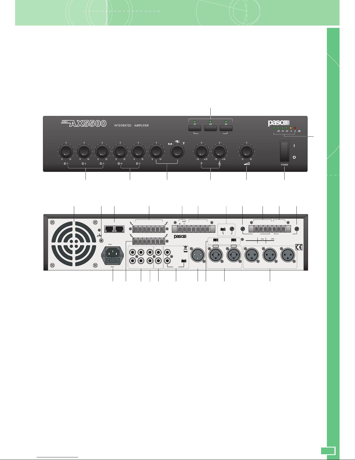
1.1 Pannello frontale
1. Controlli di livello ingressi microfonici.
2. Controlli di livello ingressi 4 e 5.
3. Controllo di livello e selezione ingressi ausiliari.
4. Controlli di tono.
5. Controllo di volume generale.
6. Interruttore di rete.
7. Visualizzatore del livello d'uscita.
8. Tasti inserzione musica.
1.2 Pannello posteriore
9. Presa di aerazione ventola di raffreddamento.
10. Connessione telaio.
11. Morsettiera uscita altoparlanti.
12. Morsettiera per alimentazione esterna in corrente continua.
13. Connessioni precedenza e override.
14. Attivazione e regolazione di livello segnale di preavviso.
15. Regolazione di livello uscita MUSIC ON HOLD.
16. Uscite di linea e di potenza MUSIC ON HOLD.
17. Ingresso emergenza da centralino telefonico.
18. Regolazione di livello ingresso telefonico.
19. Ingressi microfonici.
20. Ingressi MIC/LINE.
21. Selettori modalità funzionamento ingressi 4 e 5.
22. Uscita di linea.
23. Presa per equalizzatore esterno.
24. Uscita per registratore.
25. Ingressi ausiliari.
26. Morsettiera selezione zone.
27. Spina di rete con fusibile incorporato.
28. Selettore della tensione di rete (pannello inferiore).
29. Prese per connessione postazioni microfoniche.
1. GENERAL DESCRIPTION
1.1 Front panel
1. Level control for microphone inputs.
2. Inputs 4 and 5 level control.
3. Level control and selection of auxiliary inputs.
4. Tone controls.
5. General volume control.
6. Mains switch.
7. Output level indicator.
8. Music activation keys.
1.2 Rear panel
9. Cooling fan air intake.
10. Frame connection.
11. Loudspeakers output terminal strip.
12. Terminal strip for external DC power supply.
13. Precedence and override connections.
14. Activation and level control of the warning signal.
15. MUSIC ON HOLD output level adjustment.
16. MUSIC ON HOLD line and power outputs.
17. Emergency input from PABX.
18. Telephone input level adjustment.
19. Microphone inputs.
20. MIC/LINE inputs.
21. Inputs 4 and 5 mode selector switches.
22. Power output.
23. Socket for an external equaliser.
24. Output for recorder.
25. Auxiliary inputs.
26. Zone selection terminal strip.
27. Mains plug with built-in fuse.
28. Mains voltage selector switch (bottom panel).
29. Sockets for connecting microphone stations.

DATASHEET
αα
αα
α
4
2. AVVERTENZE
2.1 Note di sicurezza
Durante il funzionamento dell’apparecchio è necessario assicurare
un’adeguata ventilazione. Evitare di racchiudere l’apparecchio in un
mobile privo di aerazione o di ostruire le fessure di ventilazione ed in
particolare la presa d’aria posteriore della ventola di raffreddamento.
Evitare inoltre di tenere l’apparecchio in prossimità di sorgenti di calore.
Questo apparecchio è predisposto per il montaggio in mobile rack
standard 19” tramite l’uso degli accessori opzionali AC5500 e AC50.
Si consiglia di interporre un pannello di aerazione tra un apparecchio e
l’altro. Ogni intervento all’interno dell’apparecchio, quale la selezione
di alcuni modi d’uso o la sostituzione di fusibili, deve essere effettuato
solo da personale specializzato: la rimozione del coperchio rende
accessibili parti con rischio di scosse elettriche. Prima di rimuovere il
coperchio accertarsi sempre che il cavo di rete sia staccato. Nel caso
di accidentale caduta di liquidi sull’apparecchio, staccare
immediatamente la spina di rete ed interpellare il centro di assistenza
PASO più vicino. La connessione di telaio (10) consente di collegare
altre apparecchiature per la sola funzione di schermatura dei segnali a
basso livello: questa presa non deve essere utilizzata per il collegamento
di sicurezza del telaio alla terra.
2.2 Alimentazione
Questi apparecchi sono predisposti per il funzionamento con tensione
di rete a 230 V ± 10% 50/60 Hz. È possibile utilizzare l’apparecchio
anche con una tensione di rete di 115 V ± 10% 50/60 Hz; a tal scopo
è necessario portare il selettore (28) posto sul pannello inferiore in
posizione “115 V”. Gli amplificatori della Serie AX5500 possono anche
essere alimentati con una sorgente esterna di corrente continua con
tensione di 24 V che deve essere applicata, rispettando le polarità, ai
relativi terminali della morsettiera (12). In accordo con le normative
di sicurezza, l’interruttore di accensione (6) agisce solo sulla tensione
di rete. In dotazione all’apparecchio é fornito un cavo di alimentazione
con filo di terra; il terminale di terra della spina di rete non deve
essere rimosso in alcun caso. Collegare la spina di rete (27)
dell’apparecchio alla rete elettrica utilizzando l’apposito cavo fornito
in dotazione; assicurarsi che la presa di corrente sia dotata di
collegamento di terra a norma di legge. L’apparecchio è protetto da
due fusibili (vedi par. 4.4).
3. CONNESSIONI
3.1 Criteri generali
Per un corretto funzionamento dell’apparecchio è opportuno osservare
alcuni criteri di massima nell’esecuzione dei collegamenti:
• non posizionare cavi e microfoni sul mobile dell’apparecchio.
• evitare di stendere le linee di segnale parallele a quelle di rete;
osservare una distanza minima di 30/40 cm.
• posizionare le linee di ingresso e le linee di uscita distanti tra loro.
• posizionare i microfoni al di fuori dell’angolo di radiazione dei diffusori
sonori per evitare il fenomeno di reazione acustica (effetto Larsen).
3.2 Ingressi microfonici
Alle prese XLR MIC.1, MIC.2 e MIC. 3 (19) è possibile collegare
microfoni PASO di tipo dinamico e ad elettrete con alimentazione
Phantom; i collegamenti a queste prese sono riportati nella Fig. 3.2.1.
Ulteriori possibilità di connessione, che sfruttano l’uso della morsettiera
(13), sono riportate al par. 3.9.
Fig. 3.2.1
1 schermo/shield
2 segnale (caldo)/signal (hot)
3 segnale (freddo)/signal (cold)
12
3
1 segnale (caldo)/signal (hot)
2 segnale (lato freddo)/signal (cold)
3 schermo/shield
12
3
Collegamento bilanciato • Balanced connection Collegamento sbilanciato • Unbalanced connection
12
1 segnale/signal
2 schermo e massa/shield and GND
1 schermo e massa/shield and GND
2 segnale/signal
3 schermo e massa/shield and GND
12
3
2. WARNINGS
2.1 Safety notes
While the equipment is working, it is necessary to provide adequate
ventilation. Do not close this equipment inside an unventilated cabinet
and do not obstruct the air vents, in particular not the air intake on the
rear for the cooling fan.
Do not keep the equipment in the vicinity of sources of heat.
This equipment has provisions for mounting in a standard 19" rack cabinet
using the optional accessories AC5500 and AC50. It is recommended
that you place a ventilation panel between one piece of equipment
and the next. Any activities inside the apparatus, such as selecting
some of the operating modes, the installation of accessories or the
replacement of fuses, must be carried out by specialized personnel
only: when the cover is removed, parts liable to cause electric shocks
are exposed. Before removing the cover, always make sure that the
power cord has been disconnected. In the event that liquid is
accidentally spilt onto the apparatus, disconnect the mains plug
immediately and contact the nearest PASO Service Centre.
The chassis connection (10) may be used to connect other equipment
only for the purpose of shielding the low signals: this socket may not
be used to connect the chassis to earth for safety purposes.
2.2 Power supply
This equipment is designed for use with a mains voltage of 230 V ± 10%
50/60 Hz. It is also possible to use the equipment with a mains voltage
of 115 V ± 10% 50/60 Hz, but to do so it is necessary to place the
selector switch (28) on the bottom panel in the “115 V” position.
The amplifiers of the AX5500 Series can also be powered by means of
an external DC power supply with a voltage of 24V, which has to be
applied to the appropriate terminals on the terminal strip (12) paying
attention to the correct polarity. As required under safety regulations,
the ON/OFF switch (6) only controls the mains voltage. The equipment
is supplied with its own power-supply cable, which is equipped with an
earthing wire. The earth terminal of the mains plug should never be
removed under any circumstances. Connect the mains plug (27) of the
equipment to the power mains using the cable included in the supply.
Make sure that the power outlet is equipped with a connection to earth
in accordance with the law. The equipment is protected by two fuses
(see point 4.4).
3. CONNECTIONS
3.1 General features
For proper unit operation, use the following instructions when making
the connections:
• Do not place cables or microphones on the unit cabinet;
• Do not lay signal lines parallel to power lines; ensure a minimum
distance of 30/40 cm between them;
• Keep input lines and the output lines far apart;
• Keep the microphones outside the operating span of the speakers
to avoid acoustic feedback (Larsen effect).
3.2 Microphone inputs
It is possible to connect PASO microphones of the dynamic or of the
electret type with a Phantom power supply to the XLR sockets MIC.1,
MIC.2 and MIC.3 (19). The connections to these sockets are shown
in Figure 3.2.1. Further possible connections exploiting the terminal
strip (13) are indicated under point 3.9.
DATASHEET
AX5500 SERIES
5
Ogni ingresso microfonico dispone di un proprio controllo di livello (1)
per dosare opportunamente l’ampiezza dei vari segnali. L’ingresso
microfonico MIC.1 dispone, inoltre, della funzione di precedenza
automatica (VOX): parlando al microfono collegato a questo ingresso
verranno automaticamente ammutoliti tutti gli ingressi (microfonici e
ausiliari) tranne quello d’emergenza telefonico.
Il livello della soglia di attivazione del circuito di precedenza automatica
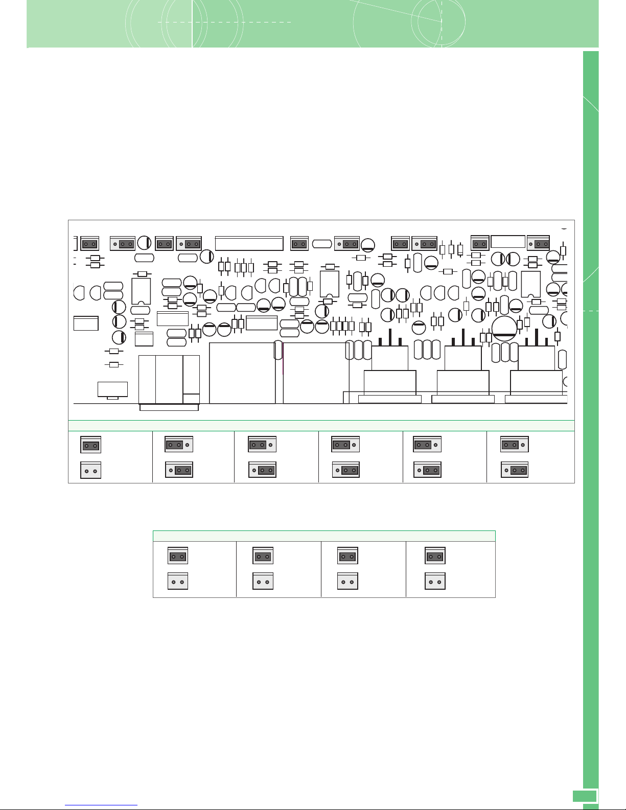
è indipendente dalla posizione del controllo MIC.1 (1). La funzione
VOX può essere disattivata estraendo il ponticello interno CN104 (vedi
tabella). Negli ingressi microfonici MIC.1, MIC.2 e MIC.3 l’alimentazione
Phantom è fissa.
Ogni ingresso microfonico è dotato di un apposito filtro parola che migliora
la riproduzione vocale, in particolar modo con diffusori a tromba.
Per inserire i filtri, spostare i jumper come indicato in tabella:
É possibile disattivare la funzione di MUTING degli ingressi MIC.2 -
MIC.3 - INPUT 4 - INPUT 5 togliendo il relativo jumper, come indicato
in tabella:
3.3 Ingressi MIC/LINE
Le prese INPUT 4 ed INPUT 5 (20) sono configurabili in modo
indipendente come ingressi microfonici (con o senza alimentazione
Phantom) o come ingressi di linea. La selezione della modalità è ottenuta
tramite i deviatori a tre posizioni (21):
• in posizione MIC, si seleziona la sensibilità microfonica con
alimentazione phantom disattivata;
• in posizione PH, si seleziona la sensibilità microfonica attivando
l’alimentazione phantom (per microfoni elettrete 12/24V);
• in posizione LINE, si seleziona la sensibilità di linea.
É possibile effettuare il collegamento sia con spine di tipo XLR maschio
che con spinotto jack 1/4”. I collegamenti a queste prese sono riportati
nella Fig. 3.2.1. Ogni ingresso dispone di un proprio controllo di livello
(2) per dosare opportunamente l’ampiezza dei vari segnali.
R
C127
R129
CN126
R136
C130
R199
C192
C190
U104
R198
C18
8
C191
R102
R103
R202
C182
G
R197
MIC108 MIC107
MIC109
C183
C193
C194
R107
R108
R106
C187
R2
C128
C186
C102
R109
C103
R1
C196
R101
R128
C107
R110
C101
C198
R131
C197
C105
C104
C184
C112
R104
R105
C199
R114
R116
Q112 Q113 Q111
R115
R118
C113C109
C110
C136
R139
R142
C134
C135
R137
R133
R135
D103
CN104
R130
R132
C131 C129
CN127
CN128
R138
C137
CN130 CN129
CN138
C185
C115
C116
C111
R113
R112
R120
R122
R117
R119R123
R134
C117
U105
R140
R111
R141
C108
R147
R143
R167
R144
R154
C118
Q116 Q117
R126
R125
C125C121
R121
C133
C132
C120 C123
CN101
CN133
R145
R149
R152
R148
R151
C141
R153
C157
R150
C143
C158
C162
R193
R194
C155
C155
R189 C144
R190
C156 C159
R191
R192
C152
C124
R124C122C119
Q114 Q115
C163
DJMIC1
DJMIC2
R195
R196
C150
C161
CN147
C148
R188
R186
R185
C160
CN144
CN140
C151
C153
C139
R200
R201
C132
C131
R147
C145
R169
R170
CN136
R171
C154
U106
SW102
C140
Q123Q124
72
MIC111
* impostazione di fabbrica/factory setting.
Each microphone input has its own level control (1) so that the amplitude
of the various different signals can be suitably adjusted. The MIC.1
microphone input also has an automatic priority function (VOX): when
speaking through the microphone connected to this input, all the
inputs (microphone and auxiliary) will be muted except for the
emergency telephone input.
The level of the threshold for activating the automatic priority circuit
does not depend on the position of the MIC.1 control (1). The VOX
function can be de-activated by removing internal jumper CN104 (see
table). In microphone inputs MIC.1, MIC.2 and MIC.3 the Phantom
power supply is fixed.
Each microphone input has a special speech filter that improves the
reproduction of speech, in particular with horn loudspeakers.
To include the filters, move the jumpers as shown in the table:
It is possible to de-activate the MUTING function of inputs MIC.2 -
MIC.3 - INPUT 4 and INPUT 5 by removing the relevant jumper, as
shown in the table:
3.3 MIC/LINE Inputs
The INPUT 4 and INPUT 5 sockets (20) can be separately configured
as microphone inputs (with or without phantom power supply) or as
line inputs. The modes are selected by means of the three-position
(21):
• in the MIC position the sensitivity of the microphone with the
phantom power supply de-activated is selected;
• in the PHANTOM position the sensitivity of the microphone with the
phantom power supply activated (for 12/24V electret microphones)
is selected;
• in the LINE position the sensitivity of the line is selected.
It is possible to make the connections either with male XLR plugs or
with 1/4” jacks. The connections to these sockets are shown in Figure
3.2.1. Each input has its own level control (2) so as to be able to
adjust the amplitude of the various different signals suitably.
CN129
MIC.3
Filter ON
MIC.3
Filter OFF*
CN127
MIC.2
Filter ON
MIC.2
Filter OFF*
CN131
INPUT 4
Filter ON
INPUT 4
Filter OFF*
CN145
INPUT 5
Filter ON
INPUT 5
Filter OFF*
CN104
VOX MIC.1
ON*
VOX MIC.1
OFF
CN126
MIC.1
Filter ON
MIC.1
Filter OFF*
CN128
MIC.2
Mute ON*
MIC.2
Mute OFF
CN136
INPUT 5
Mute ON*
INPUT 5
Mute OFF
CN132
INPUT 4
Mute ON*
INPUT 4
Mute OFF
CN130
MIC.3
Mute ON*
MIC.3
Mute OFF
DATASHEET
αα
αα
α
6
3.4 Ingressi ausiliari
Alle prese phono TUNER, TAPE e CD (25) è possibile collegare 3
sorgenti musicali ad alto livello (lettore di compact disc, riproduttore a
nastro, sintonizzatore, radioricevitore per microfoni senza filo, ecc.).
La doppia presa consente un veloce collegamento della sorgente
all’amplificatore tramite cavetto stereo: la miscelazione dei due canali
destro e sinistro (L/R) è realizzata internamente. La selezione e la
regolazione di livello della sorgente avviene tramite l’apposito controllo
(3) posto sul pannello frontale dell’apparecchio. La sorgente selezionata
è soggetta all’ammutolimento sia per precedenza automatica (VOX)
degli ingressi TELEPHONE e MIC.1 che per la chiusura del contatto PR
(precedenza).
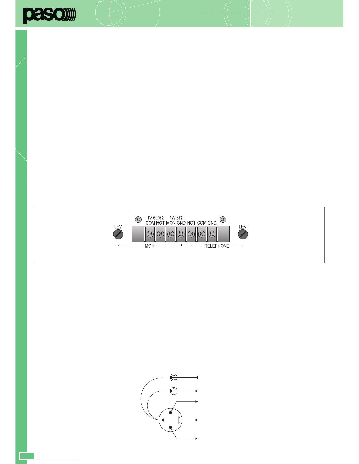
3.6 Uscita “Music On Hold” (MOH)
A questi morsetti (16) è disponibile il segnale della sola sorgente
selezionata sugli ingressi ausiliari (25); tale segnale non è soggetto
all’azione di precedenza microfonica o telefonica. In particolare, l'uscita
bilanciata a trasformatore (morsetti COM-HOT di fig. 3.6.1) può essere
utilizzata per il pilotaggio di un ulteriore amplificatore, di un centralino
telefonico od altro; l'uscita di potenza (morsetti MON-GND) è in grado
di pilotare direttamente un piccolo altoparlante monitor da 8 ohm con
potenza massima di 1 W. É possibile regolare il livello di uscita agendo
sul controllo LEV. (15).
3.5 Ingresso telefonico
L’apparecchio è predisposto per il collegamento ad un sistema telefonico
tramite la morsettiera TELEPHONE (17). Tale ingresso è bilanciato a
trasformatore, possiede un proprio controllo di livello - LEV. (18) - ed
è dotato di circuito VOX per la diffusione dei messaggi con priorità più
elevata rispetto a qualsiasi altro ingresso.
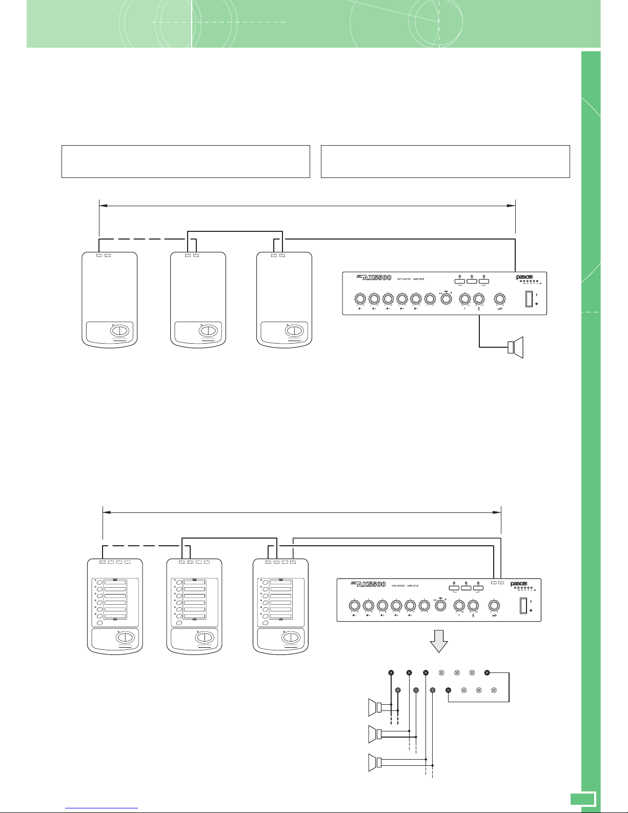
3.7 Collegamento alle postazioni
Agli amplificatori della Serie AX5500 possono essere collegate in modo
semplice e veloce due tipologie di postazioni microfoniche:
1) Postazioni non preamplificate, mod. B701-M e B701-P
2) Postazioni preamplificate, mod. B711 e B711/6
1) Le postazioni microfoniche B701-M e B701-P, caratterizzate
rispettivamente da un microfono dinamico e da uno elettrete, sono
entrambe dotate di due tasti: uno a rilascio - per i messaggi brevi ed uno a ritenuta, per messaggi lunghi. Per il collegamento è
necessario inserire la spina XLR della base in uno qualsiasi degli
ingressi microfonici dell'amplificatore; il cavetto di colore bianco
deve essere collegato al terminale +12V della morsettiera di
precedenza e quello di colore verde al terminale di precedenza
(PR).
2
3
1
Bianco
+ 12V
Verde
PREC.
SIGNAL +
SHIELD
SIGNAL –
White
Green
Nota: se il modello B701-P viene collegato agli
ingressi INPUT 4 o INPUT 5, è indispensabile
posizionare il relativo selettore in posizione 'PH'.
In questo caso, se non si vuole utilizzare la
precedenza, i cavetti di colore bianco e verde NON
devono essere collegati. È possibile utilizzare
contemporaneamente queste postazioni e
l'ingresso telefonico.
Fig. 3.6.1
5: TEL (ingresso - lato caldo)
(input - warm side)
6: TEL (ingresso - lato freddo)
(input - cold side)
7: TEL (massa schermo)
(GND and shield)
1: 600Ω (linea - lato freddo)
(line - cold side)
2: 600Ω (linea - lato caldo)
(line - warm side)
3: 1W/8Ω uscita altoparlanti
loudspeakers output
4: massa e schermo
GND and shield
Fig. 3.7.1
3.4 Auxiliary inputs
It is possible to connect two high-level sources of music (CD player,
tape recorder, tuner, radio-receiver for wireless microphones, etc.) to
the TUNER, TAPE and CD (25) phono sockets. Thanks to the fact
that there are two sockets, it is easy to connect the source rapidly to
the amplifier by means of a stereo cable: mixing of the two channels
(left and right - L/R) is carried out internally. The source is selected by
means of the selector (3) provided for this purpose on the front panel
of the equipment. The source that is selected is subject to muting both
as a result of automatic priority (VOX) of the TELEPHONE and MIC.1
inputs and due to closing of the PR contact (priority).
3.6 “Music On Hold” output (MOH)
The signal of the only source selected on the auxiliary inputs (25) is
available on these terminals (16). This signal is not affected by the
use of telephone precedence. In particular, the balanced transformer
output (strips COM-HOT, Fig. 3.6.1) can be used to drive an additional
amplifier, a telephone exchange or other equipment. The power output
(terminals MON-GND in Figure 3.6.1) is capable of driving directly a
small 8 ohm monitoring loudspeaker with a maximum output of 1 W. It
is possible to adjust the output level by means of the LEV. control
(15).
3.5 Telephone input
The equipment has provisions for connection of a telephone system
by means of the TELEPHONE terminal strip (17). This input is balanced
by a transformer, has its own level control - LEV. (18) - and is equipped
with a VOX circuit for broadcasting messages with a higher priority
level than any other input.
3.7 Connection to microphone stations
It is possible to connect two types of microphone stations to the
amplifiers of the AX5500 range:
1) Non-preamplified stations, models B701-M and B701-P
2) Preamplified stations, models B711 and B711/6
1) The B701-M and B701-P microphone stations, characterised by a
dynamic microphone and by an electret microphone respectively,
both have two keys, one of which is a hold-down button for short
messages and the other a toggle button for long messages. To
make the connection, it is necessary to plug the XLR connector of
the base into any of the microphone inputs on the amplifier. The
white lead must be connected to the +12V terminal on the
precedence terminal strip and the green lead must be connected
to the (PR) precedence terminal.
Note: If the B701-P is connected to INPUT 4 or
INPUT 5, it is essential to position the related
switch on 'PH'. In this case, if you do not want to
use the precedence, the white and green leads
must NOT be connected. It is possible to use this
station and the telephone input simultaneously.
1234567
DATASHEET
AX5500 SERIES
7
PROGRAMINSERTION
ON
AUDIO IN
Up to B711/6 - MAX 100 m3
ALL
PTT LOCK
PTT LOCK
IN
OUT
7÷12
1÷6
CONTACT IN
ALL
PTT LOCK
PTT LOCK
IN
OUT
7÷12
1÷6
ALL
PTT LOCK
PTT LOCK
IN
OUT
7÷12
1÷6
0VZ10V
Z2
ZONE
1
ZONE
2
0V
Z3
ZONE
3
8
VIN
50VC170VC2100V
C3
2) Le postazioni microfoniche preamplificate B711 e B711/6 sono
caratterizzate entrambe da un microfono elettrete e consentono di
inviare messaggi su una o più zone d'ascolto. Per il collegamento
di questi due modelli, è INDISPENSABILE utilizzare dei cavi
STP CAT5.E (schermati).
La regolazione del livello d'uscita è disponibile al controllo TELEPHONE
LEV. (fig. 3.6.1).
PROGRAMINSERTION
ON
AUDIO IN
AUDIO OUT
AUDIO IN
AUDIO IN
AUDIO OUT
AUDIO IN
AUDIO OUT
Up to B711 - MAX 100 m3
PTT LOCK
PTT LOCK
PTT LOCK
PTT LOCK
PTT LOCK
PTT LOCK
Importante!
Queste basi non devono essere utilizzate contemporaneamente
all’ingresso telefonico.
3.8 Selezione zone d’ascolto
Gli apparecchi consentono l’attivazione/disattivazione della musica di
sottofondo nella zona prescelta tramite gli interruttori Z1, Z2 e Z3
‘PROGRAM INSERTION’ posti sul frontale (8). L’avvenuta attivazione
della musica nella zona desiderata è evidenziata dal relativo led. Nel
caso si utilizzino le postazioni B711/6, la selezione zone verrà
automaticamente effettuata tramite la connessione alla presa
CONTACT IN: nella fig. 3.8.1 viene illustrato l’esempio di collegamento
per un impianto di chiamata a tre zone. Qualora si volesse invece
effettuare questa commutazione zone senza utilizzare le postazioni, è
possibile sfruttare i contatti C1, C2 e C3 collegandoli al +12V.
Fig. 3.8.1
Fig. 3.7.2
2) The B711 and B711/6 preamplified microphone stations are both
characterised by electret microphones and can be used to send
messages to one or more listening zones. To connect these two
models, it is ESSENTIAL to use STP CAT 5.E cables (shielded).
It is possible to adjust the output level by means of the TELEPHONE
LEV. control (fig. 3.6.1).
3.8 Selection of listening zones
The equipment enables background music to be activated/de-activated
in a chosen zone by means of the ‘PROGRAM INSERTION’ Z1, Z2
and Z3 switches on the front panel (8). The LED associated with the
zone in question will light up to show that the music has been activated.
If B711/6 stations are used, the zones will be selected automatically
by connection to the CONTACT IN socket: Fig. 3.8.1 shows an
example of connection for a three-zone calling system. If, instead,
you wish to carry out switching of the zones without using the stations,
it is possible to exploit contacts C1, C2 and C3, connecting them to
the +12V terminal.
Important!
These bases must not be used at the same time as the telephone
input.

DATASHEET
αα
αα
α
8
3.9 Precedenza microfonica e segnale di preavviso
Chiudendo i contatti PR e +12V della morsettiera (13) vengono
ammutoliti tutti gli ingressi tranne MIC.1; gli ingressi MIC.2, MIC.3,
INPUT 4 e INPUT 5 possono non essere ammutoliti togliendo i relativi
ponticelli CN128, CN130, CN132 e CN136 posti all’interno
dell’amplificatore stesso. La chiusura del contatto genera un segnale
di preavviso a due toni (CHIME) quando il selettore CHIME (14) si
trova in posizione ON: è possibile modificare il livello del segnale di
preavviso agendo sul relativo trimmer LEV. Per sfruttare efficacemente
la funzione di precedenza è possibile utilizzare il microfono PASO mod.
M906 e le basi B701-M e B701-P (le basi nel numero massimo di
tre). Nelle postazioni B711 e B711/6 il segnale di preavviso din-don
(disinseribile) è integrato nelle postazioni: nel caso si decida di utilizzare
questa funzione, è necessario disabilitare il din-don dell'amplificatore
portando il selettore CHIME in posizione OFF.
3.10 Uscite di potenza
Le uscite di potenza per i diffusori sono disponibili sulla morsettiera
(11). È possibile realizzare un impianto di diffusione sonora utilizzando
sia diffusori a bassa impedenza, sia diffusori dotati di traslatore di
linea. In entrambi i casi il carico complessivo non deve essere tale da
sovraccaricare l’amplificatore: non applicare cioè diffusori o gruppi di
diffusori con impedenza più bassa di quella nominale della presa alla
quale sono collegati. Si raccomanda inoltre di porre particolare
attenzione al calcolo delle impedenze nel caso si debbano realizzare
impianti di diffusione misti (a bassa impedenza e a tensione costante).
In tabella 3.10.1 sono riportati i valori nominali di tensione ed impedenza
per le diverse uscite.
Tab. 3.10.1
Uscita • Output AX5524 AX5512Z AX5509Z
8 Ω 43,8 V 31 V 26,8 V
50 V 10,4 Ω 20,8 Ω 27,8 Ω
70 V 20,4 Ω 40,8 Ω 54,4 Ω
100 V 41,7 Ω 83,3 Ω 111 Ω
3.10.1 Sistemi a bassa impedenza
In applicazioni che richiedono l’uso di pochi altoparlanti, la linea di
collegamento può essere connessa tra il terminale comune 0 V e la
presa 8 ohm della morsettiera (11). Il collegamento degli altoparlanti,
di tipo serie o parallelo o misto, deve fornire un’impedenza calcolata
pari o superiore ad 8 ohm. In figura 3.10.2 é riportato un esempio di
collegamento.
• Calcolo dell’impedenza nei collegamenti in serie
Nel caso di diffusori collegati in serie tra loro, l’impedenza totale è la
somma delle singole impedenze:
impedenza totale = Z1 + Z2 + Z3 + ....
• Calcolo dell’impedenza nei collegamenti in parallelo
Nel caso di diffusori collegati in parallelo tra loro, l’impedenza totale può
essere determinata mediante la seguente formula:
1
1
Z11 Z2
+
1
Z3
+ + ......
impedenza totale =
Fig. 3.10.2 Fig. 3.10.3
3.9 Microphone precedence and warning signal
When the contacts PR and +12V of the terminal strip (13) are closed,
all the inputs are muted except for MIC.1; it is possible to avoid
muting the MIC.2, MIC.3, INPUT 4 and INPUT 5 inputs by removing
the associated jumpers CN128, CN130, CN132 and CN136 situated
inside the amplifiers. Closing the contact will generate a two-tone
warning signal (CHIME) if the CHIME selector (14) is in the ON position:
it is possible to alter the level of the warning signal by means of the
associated LEV. trimmer. To exploit the precedence function effectively,
it is possible to use the PASO M906 microphone and the B701-M or
B701-P bases (a maximum of three bases).
At B711 and B711/6 stations, the warning chime (which can be
excluded) is built into the stations. If it is decided to use this function,
it is necessary to disable the chime of the amplifier by placing the
CHIME selector switch in the OFF position.
3.10 Power outputs
The power outputs for the loudspeakers are available on the terminal
strip (11). It is possible to set up a sound-broadcasting system using
either low-impedance loudspeakers or loudspeakers equipped with a
line transformer. In both cases the overall load must not be such as to
overload the amplifier. This means that you must not apply loudspeakers
or groups of loudspeakers with an impedance lower than the rated
impedance of the socket to which they are connected. It is also
necessary to pay particular attention to calculating the impedance
values if mixed broadcasting systems (low impedance and constant
voltage) are to be set up. Table 3.10.1 shows voltage and impedance
rated values for the various outputs.
3.10.1 Low-impedance systems
In applications that require the use only of a few loudspeakers, the
connecting line may be connected between the common terminal 0 V
and the 8 ohm socket of the terminal strip (11). The loudspeaker
connection, whether of the serial or parallel type or mixed, should
provide an impedance calculated to be equal to or higher than 8 ohm.
An example of a connection is shown in Figure 3.10.2.
• Calculating the impedance value in series connections
In the case of loudspeakers connected to one another in series, the
total impedance is the sum of the single impedance values:
total impedance = Z1 + Z2 + Z3 + ....
• Calculating the impedance value in parallel connections
In the event of loudspeakers connected in parallel to one another the
total impedance can be calculated by means of the following formula:
1
1
Z11 Z2
+
1
Z3
+ + ......
total impedance =
24V
C3C2C1VINZ3Z2Z1
100V70V50V8W0V0V0V OVR+24VGND+12VPR
S.p.A. -ITALY
: DO NOT OBSTRUCT
NING.REPLACE FUSE
IN AUDIO IN
ASE
16 16
24V
C3C2C1VINZ3Z2Z1
100V70V50V8W0V0V0V OVR+24VGND+12VPR
S.p.A. -ITALY
: DO NOT OBSTRUCT
NING.REPLACE FUSE
IN AUDIO IN
ASE
20 W 20 W

DATASHEET
AX5500 SERIES
9
3.10.2 Sistemi a tensione costante
Nel caso di impianti con un gran numero di diffusori e/o con distanze tra
amplificatori ed altoparlanti molto elevate é preferibile utilizzare un
sistema di distribuzione a tensione costante (definito anche ad alta
impedenza). In questo tipo di impianto, i diffusori, provvisti di
trasformatori di adattamento di impedenza, sono tutti collegati in
derivazione alla linea (vedi es. di Fig. 3.10.3); questo particolare rende
di facile realizzazione l’impianto e, nel caso in cui un altoparlante
dovesse per qualche motivo scollegarsi dalla linea, il resto dell’impianto
proseguirebbe nel suo regolare funzionamento. Le tensioni costanti
disponibili in uscita dall’amplificatore sono 50, 70 e 100 V.
• Calcolo del numero di diffusori (tramite le potenze)
Si supponga di avere definito sia l'amplificatore (cioè la sua potenza di
uscita) che il tipo di diffusore con relativa potenza assorbita.
In questo caso il massimo numero di diffusori collegabile sulla linea è
determinato dalla seguente formula:
potenza amplificatore
potenza diffusore
numero diffusori =
Esempio: si utilizzino un amplificatore AX5524 con plafoniere modello
Paso C58/6-TB. L'amplificatore è in grado di erogare una potenza
pari a 240 W, mentre un diffusore assorbe una potenza di 6 W.
Per sapere quanti diffusori sono collegabili alla linea di uscita si calcola:
240 W
6 W
= 40
numero diffusori =
• Calcolo del numero di diffusori (tramite le impedenze)
Se il dato disponibile è l'impedenza del diffusore, il numero massimo di
diffusori collegabili ad una linea è:
numero diffusori =
impedenza diffusore
impedenza amplificatore
NOTA BENE: nel caso più generale in cui i diffusori sono di diverso tipo
e/o collegati con differente potenza, è importante verificare sempre
che la potenza complessiva richiesta dai diffusori (ottenuta
semplicemente dalla somma delle singole potenze) sia inferiore a quella
nominale dell’amplificatore.
dove l'impedenza nominale dell'amplificatore è ricavabile dalla
tabella 3.10.1.
Esempio: si utilizzino un amplificatore AX5524 con diffusori tipo
Paso C55, che presentano una impedenza pari a 500 ohm.
Dalla tabella 3.10.1 si trova che l'impedenza nominale di carico della
linea a 100 V è pari a 41,7 ohm. Quindi:
500 Ω
41,7 Ω
numero diffusori =
= 12
3.11 Uscita registratore e presa equalizzatore
Nei casi in cui fosse richiesta una elaborazione acustica del segnale,
è possibile collegare un equalizzatore, od altro elaboratore di
segnale, alle prese PWR IN e PRE OUT (23) dell’apparecchio. Per
l'inserzione dell'equalizzatore, l'interrutore LINK posto sul retro
dell'apparecchio deve essere nella posizione OFF. Questa
realizzazione permette la correzione acustica di ambienti
particolarmente riverberanti e la soppressione della retroazione
acustica diffusore-microfono (effetto Larsen). Se all'amplificatore
non sono collegate, tramite le prese PWR IN e PRE OUT,
apparecchiature esterne, l'interruttore LINK deve essere posto in
posizione ON per mantenere la continuità della catena amplificatrice.
Alla presa di uscita TAPE OUT (25) è disponibile il segnale di
pilotaggio della parte di potenza costituito dalla miscelazione delle
diverse sorgenti prima del controllo di volume generale (5). Tale
segnale può essere utilizzato per il pilotaggio di unità di potenza e/
o inviato ad una piastra di registrazione.
L’uscita LINE OUT (22) è un uscita bilanciata che può essere
sfruttata per il collegamento ad un eventuale amplificatore di
potenza esterno (booster).
3.10.2 Constant voltage systems
When a large number of speakers is used and/or the speakers are
placed far from the amplifiers, constant voltage distribution system
should be used (also known as high-impedance systems). In this
type of system, the speakers are fitted with impedance adaptation
transformers and all of them have shunt line connections (see example
of Fig. 3.10.3). This simplifies the layout of the system and if, for any
reason, a loudspeaker is disconnected from the line, the rest of the
system will continue to work properly. The constant voltages output
from the amplifier are 50, 70 and 100 V.
• Determining the number of speakers (through power values)
If both the amplifier (i.e. its output power) and the type of speaker
with its power consumption have been established, the maximum
number of speakers which may be connected to the line may be
determined as follows:
amplifier power
speaker power
number of speakers =
Example: in a system including a AX5524 amplifier with ceiling
speakers type Paso C58/6-TB is used, the amplifier can supply 240 W
power whereas the speaker has a power consumption of 6 W.
The number of speakers which may be connected to the output line is:
240 W
6 W
= 40
number of speakers =
• Determining the number of speakers (through impedance)
If the impedance of the speaker is known, the maximum number of
speakers which may be connected to the line is:
number of speakers =
speaker impedance
amplifier impedance
N. B.: In the more general case of a system including loudspeakers of
different types or connected with different outputs, it is always
important to make sure that the overall power required by the
loudspeakers (which can be calculated simply by adding up the output
power of the single units) is lower than the rated power of the amplifier.
where the amplifier rated impedance may be determined referring to
Table 3.10.1.
Example: If a AX5524 amplifier is used with speakers type Paso C55
having a 500 ohm impedance, the rated load impedance of the
line at 100 V may be determined from Table 3.10.1 as being equal to
41,7 ohm. Thus:
500 Ω
41,7 Ω
= 12
3.11 Recorder output and equaliser socket
In those cases in which acoustic processing of the signal is required, it
is possible to connect an equaliser or other signal processing equipment
to the PWR IN and PRE OUT sockets (23) on the equipment. When
inserting the equaliser, the LINK switch on the rear of the equipment
must be in the OFF position. This application enables acoustic correction
of rooms subject to particularly severe reverberation and the
suppression of acoustic feedback between loudspeakers and
microphones (Larsen effect).
If no external equipment is connected to the amplifier by means of the
PWR IN and PRE OUT sockets, the LINK switch must be in the ON
position in order to maintain continuity of the amplifier chain.
The signal driving the power part consisting of the signal resulting
from the mixing of the various sources before the master volume control
(5) is available on the TAPE OUT output socket. This signal can be
used to drive power units and/or sent to a recording deck.
The LINE OUT output (22) is a balanced output that can be used for
a connection to a possible external power amplifier (booster).
number of speakers =

DATASHEET
αα
αα
α
10
4. USO DELL’APPARECCHIO
4.1 Accensione
Prima di mettere in funzione l'apparecchio accertarsi di avere realizzato
tutte le connessioni necessarie al completamento dell'impianto e di
aver effettuato le impostazioni di funzionamento.
Portare l'interruttore di rete (6) in posizione ON.
Se necessario, regolare il livello di ascolto tramite il controllo (5) e
ritoccare i livelli delle sorgenti sonore per una corretta equalizzazione
dei segnali tramite i controlli di livello (1), (2), (3) e (4).
4.2 Controllo di volume principale
Il controllo di volume principale (5) regola il livello complessivo del segnale
d’uscita, derivato dalla miscelazione dei vari segnali di ingresso. Per
ottenere in uscita un segnale privo di distorsione, si raccomanda di
controllare che sull'indicatore del livello di uscita (7) non si accenda la
spia di colore rosso (0 dB) o, comunque, che ciò avvenga saltuariamente;
in caso contrario, è necessario diminuire il livello di uscita agendo sul
comando (5). La potenza di uscita nominale è segnalata dall'accensione
della spia luminosa rossa (0 dB).
4.3 Correzione acustica
I controlli BASS e TREBLE (4) modificano la tonalità del segnale di
uscita derivato dalla miscelazione dei vari segnali di ingresso.
• Controllo toni bassi (BASS)
Il controllo BASS regola le prestazioni dell'amplificatore alle basse
frequenze. La posizione di centro, indicata dallo “0”, fornisce una
risposta lineare; per avere una esaltazione delle frequenze basse
ruotare la manopola in senso ORARIO. Utilizzando diffusori a tromba è
opportuno tramite il comando BASS, attenuare le frequenze basse; un
eccessivo livello delle basse frequenze potrebbe danneggiare la
membrana del diffusore.
• Controllo toni acuti (TREBLE)
Il controllo TREBLE regola le prestazioni acustiche dell'amplificatore
alle alte frequenze. La posizione di centro, indicata dallo “0”, fornisce
una risposta di tipo lineare; per avere una esaltazione delle frequenze
alte ruotare la monopola in senso ORARIO. L’attenuazione dei toni
acuti è utlie per minimizzare un eccessivo livello di fruscio o per rendere
più dolci suoni particolarmente sibilanti.
4.4 Sovraccarico e protezione
Applicare un valore di impedenza di carico inferiore a quella nominale
significa richiedere all'apparecchio una potenza superiore a quella
erogabile con continuità. Questo potrebbe portare al danneggiamento
degli stadi finali di potenza e dei trasformatori di alimentazione e di
uscita. Per non incorrere in questi inconvenienti gli amplificatori della
Serie AX5500 sono abbondantemente dotati di circuiti e dispositivi di
protezione contro i sovraccarichi ed i cortocircuiti:
• circuito limitatore di picco della corrente di uscita: il suo intervento
è istantaneo ed agisce tipicamente nel caso di sovraccarico.
• interruttore termico ripristinabile: posto a contatto del dissipatore
dei transistor di potenza, interrompe l’alimentazione dei circuiti di
pilotaggio, e di conseguenza annulla il segnale di uscita, nel caso in
cui la temperatura dei finali raggiunga valori pericolosi. Il ripristino
è automatico non appena la temperatura rientra nel range di normale
funzionamento.
• fusibili di rete - accessibile sulla presa rete (27) - e di alimentazione
interna a bassa tensione (accessibile all’interno dell’apparecchio,
sul circuito d’alimentazione): questi dispositivi garantiscono il blocco
immediato del funzionamento dell’amplificatore in caso di guasto
interno dello stesso.
Da segnalare infine che tutti i modelli sono dotati di ventola di
raffreddamento, con controllo automatico della velocità in funzione
della temperatura del dissipatore su cui sono applicati i dispositivi di
potenza.
4. OPERATION
4.1 Power on
Before starting up the equipment, make sure that all the connections
required for completing the system have been made and that all the
settings for correct operation have been made. Set the mains switch
(6) to the ON position. If necessary, adjust the listening level by
means of the control (5) and adjust the levels of the sound sources for
correct equalisation of the signals by means of the level controls (1),
(2), (3) and (4).
4.2 Master volume control
The master volume control (5) adjusts the output signal overall level
as generated by mixing different input signals.
To obtain a flutter-free output signal, check that the red LED indicator
(0 dB) on the output level indicator (7) is not on, or at any rate that
it does not light up frequently; otherwise, the output level should be
reduced by the control (5). The rated output power is reached when
the red LED indicator (0 dB) lights up.
4.3 Acoustic adjustment
The BASS and TREBLE controls (4) adjust the output signal tone
generated by mixing the different input signals.
• Bass control (BASS)
The BASS control adjusts the amplifier performance at low frequencies.
The center position “0”. provides a linear response. To emphasize low
frequencies, turn the knob clockwise; to attenuate them, turn the
knob CLOCKWISE. When horn-type speakers are used, low frequencies
should be attenuated by means of the BASS control. An excessive low
frequency level could damage the speaker diaphragm.
• Treble control (TREBLE)
The TREBLE control adjusts the amplifier performance at high
frequencies. The center position “0” provides a linear response.
To emphasize high frequencies, turn the knob clockwise; to attenuate
them, turn the knob CLOCKWISE. Attenuation of the treble tones is
useful for minimising and excessive level of rustling or in order to
soften hissing sounds.
4.4 Overload and protection
Applying a load impedance value lower than the rated loan means that
the equipment is required to supply power in excess of the capacity
that can be delivered with continuity. This could lead to damage to the
final power stages and of the power supply and output transformers.
In order not to incur these upsets, the amplifiers of the AX5500
Series are equipped with a large number of circuits and devices
protecting them against overloads and short circuits:
• output current peak limiting circuit: this is tripped instantaneously
and its typical function is in the event of overloads.
• resettable thermal circuit-breaker: this is placed in contact with the
heat sink of the power transistors. It cuts off power to the driving
circuits and therefore cancels the output signal if the temperature
of the end stages reaches hazardous levels. It resets automatically
as soon as the temperature returns to within the normal operating
range.
• Mains fuses - accessible on the mains plug (27) - and on the internal
low-voltage power supply (accessible inside the equipment, on the
power supply circuit): these devices stop the amplifier working
immediately in case of internal failure inside it.
It should be pointed out, lastly, that all the models have cooling fans,
with automatic speed control depending on the temperature of the
heat sink on which the power devices are applied.

DATASHEET
AX5500 SERIES
11
CARATTERISTICHE TECNICHE AX5509Z AX5512Z AX5524 TECHNICAL SPECIFICATIONS
Potenza di uscita nominale (230 VCA) 90 W 120 W 240 W Rated output power (230 VAC)
Potenza di uscita nominale (24 VCC) 80 W 100 W 170 W Rated output power (24 VDC)
Uscite a tensione costante 50, 70, 100 V Constant voltage outputs
Uscite a bassa impedenza 8 Ω Low impedance outputs
Distorsione alla potenza nominale <1% Distortion at rated power
Controllo toni Tones control
Toni gravi ± 11 dB (100 Hz) Bass tones
Toni acuti ± 11 dB (10 kHz) Treble tones
Ingressi microfonici 1, 2 e 3 Microphone inputs 1, 2 and 3
Sensibilità/impedenza 1 mV / 1000 Ω Input sensitivity/impedance
Rapporto segnale/disturbo 65 dB S/N Ratio
Risposta in frequenza 30 ÷ 20.000 Hz (0/-3 dB) Frequency response
Alimentazione Phantom 16,9 V Phantom supply
Ingressi microfonici 4 e 5 (pos. LINE) Microphone inputs 4 and 5 (LINE pos.)
Sensibilità/impedenza 85 mV / 1000 Ω Input sensitivity/impedance
Rapporto segnale/disturbo 80 dB S/N Ratio
Risposta in frequenza 100 ÷ 20.000 Hz (0/-3 dB) Frequency response
Ingressi microfonici 4 e 5 (pos. MIC) Microphone inputs 4 and 5 (MIC pos.)
Sensibilità/impedenza 1 mV / 1000 Ω Input sensitivity/impedance
Rapporto segnale/disturbo 62 dB S/N Ratio
Risposta in frequenza 30 ÷ 20.000 Hz (0/-3 dB) Frequency response
Ingressi ausiliari Auxiliary inputs
Sensibilità/impedenza ingresso CD 500 mV / 10 kΩ CD Input sensitivity/impedance
Sensibilità/impedenza ingresso TAPE 250 mV / 6 kΩ TAPE Input sensitivity/impedance
Sensibilità/impedenza ingresso TUNER 250 mV / 6 kΩ TUNER Input sensitivity/impedance
Rapporto segnale/disturbo 80 dB S/N Ratio
Risposta in frequenza 30 ÷ 20.000 Hz (0/-3 dB) Frequency response
Attenuazione precedenza 45 dB Precedence attenuation
Ingresso telefonico Telephone input
Sensibilità/impedenza 100 mV / 5,6 kΩ Input sensitivity/impedance
Rapporto segnale/disturbo > 80 dB S/N Ratio
Risposta in frequenza 350 ÷ 10.000 Hz Frequency response
Uscite di segnale Signal outputs
Linea MOH 1,6 V / 300 Ω MOH Line
Potenza monitor MOH 1 W / 8 Ω MOH Monitor power
Uscita PRE OUT 0,6 V / 500 Ω PRE OUT output
Uscita TAPE OUT 1,3 V / 500 Ω TAPE OUT output
Uscita LINE OUT 2,6 V / 1000 Ω LINE OUT output

DATASHEET
αα
αα
α
12
SOMMAIRE
1. Description générale
1.1 Panneau frontal ............................................................13
1.2 Panneau postérieur ....................................................... 13
2. Précautions
2.1 Conseils de securite ......................................................14
2.2 Alimentation .................................................................. 14
3. Connexions
3.1 Criteres generaux ......................................................... 14
3.2 Entrées micro ................................................................14
3.3 Entrées MIC/LINE ......................................................... 15
3.4 Entrées auxiliaires ......................................................... 16
3.5 Entrée téléphonique......................................................16
3.6 Sortie ‘Music On Hold’ (MOH) .........................................16
3.7 Raccordement aux postes microphoniques .................... 16
3.8 Selection de zones d'ecoute ..........................................17
3.9 Priorité microphonique et signal de préavis .................... 18
3.10 Sorties de puissance .....................................................18
3.10.1 Systèmes à basse impédance ............................ 18
3.10.2 Systèmes à tension constante ...........................19
3.11 Sortie enregistreur et prise egaliseur ............................. 19
4. Utilisation de l’appareil
4.1 Mise en marche ..................................................................... 20
4.2 Contrôle de volume principal .................................................. 20
4.3 Correction acoustique ........................................................... 20
- Contrôle tonalité basses (BASS) .......................................... 20
- Contrôle tonalité aigues (TREBLE) .......................................20
4.4 Surcharge et protection......................................................... 20
Caractéristiques techniques .................................................21
INHALTSANGABE
1. Allgemeine Beschreibung
1.1 Frontpaneel ..................................................................13
1.2 Rückpaneel ................................................................... 13
2. Hinweise
2.1 Sicherheitsanweisungen ................................................ 14
2.2 Einspeisung ................................................................... 14
3. Anschlüsse
3.1 Allgemeine Hinweise ...................................................... 14
3.2 Mikrofoneingänge ......................................................... 14
3.3 Eingänge MIC/LINE .......................................................15
3.4 Hilfseingänge ................................................................ 16
3.5 Telefoneingang ............................................................. 16
3.6 Ausgänge ‘Music On Hold’ (MOH) ................................... 16
3.7 Anschluss an die Sprechstellen ......................................16
3.8 Auswahl der Klangzone .................................................17
3.9 Mikrofonvorrang und Ankündigungssignal ...................... 18
3.10 Leistungausgänge ......................................................... 18
3.10.1 System mit niedriger Impedanz ..........................18
3.10.2 Systeme mit konstanter Spannung ..................... 19
3.11 Ausgang Aufnahmegerät und Buchse Equalizer .............19
4. Gebraüch des Gerates
4.1 Einschalten
............................................................................ 20
4.2 Steuerung der Hauptlautstärke ............................................. 20
4.3 Tonkorrektur ......................................................................... 20
- Tiefenkontrolle (BASS) ........................................................20
- Kontrolle hohe töne (TREBLE).............................................. 20
4.4 Überlastung und Schutz......................................................... 20
Technische Eigenschaften .....................................................21
GARANTIE
Für dieses Produkt wird eine Garantie für Rohmaterialfehler und
Montagefehler gewährt; die Garantiezeit unterliegt den gültigen gesetzlichen
Bestimmungen. Paso repariert das garantierte Produkt kostenlos, wenn
sich herausstellt, dass der Defekt während des normalen Gebrauchs
aufgetreten ist; die Garantie erstreckt sich demnach nicht auf Produkte, die
falsch gebraucht und installiert oder mechanisch, durch Flüssigkeiten oder
Umwelteinflüsse beschädigt wurden. Das defekte Produkt muss franco
Versandkosten für den Hin- und Rücktransport zu und von Paso gesendet
werden. Diese Garantie schließt keine weiteren, expliziten oder impliziten
Leistungen und Folgeschäden an Personen, Gegenständen oder Unfälle
ein. Bitte wenden Sie sich an PASO-Fachhandel in Ihrer Gegend, wenn Sie
weitere Informationen zu dieser Garantie wünschen.
Wichtig! Der Kunde muss einen Verkaufsbeleg (Rechnung oder Quittung)
vorlegen, wenn er Serviceleistungen, die unter die Garantie fallen, in
Anspruch nehmen möchte. Er muss zu diesem Zweck außerdem das
Kaufdatum angeben sowie das Modell und die Seriennummer, die auf dem
Gerät vermerkt sind. Diese Daten müssen in den unten stehenden Textkasten
eingetragen werden.
Les amplificateurs PASO sont construits conformément aux normes
internationales de sécurité. Pour étendre cette garantie également aux
installations dont ces appareils font partie intégrante, il est important de
prendre connaissance de toutes les caractéristiques en lisant attentivement
ces instructions et en particulier les notices de sécurité.
Die PASO - Geräte werden unter Befolgung der internationalen
Sicherheitsvorschriften gebaut.Um diese Garantie auch auf Einbauten
auszudehnen, von denen diese Geräts ein wesentlicher Bestandteil sind, ist
es wichtig über aller Eigenschaften Bescheid zu wissen und insbesondere
der Sicherheitsanweisungen aufmerksam zu lesen.
GARANTIE
Ce produit est garanti comme étant exempt de défauts de matières
premières et de fabrication. La durée de la garantie est conforme aux
normes en vigueur. Paso réparera gratuitement tout produit défectueux
en garantie dès lors que l'anomalie se vérifiera dans le cadre d'une
utilisation normale du produit. La garantie ne couvre donc pas les
produits utilisés et installés de façon erronée, endommagés mécaniquement
ou encore souillés par des liquides ou des agents atmosphériques. Le
produit défectueux devra être envoyé à Paso franco de frais d'expédition
et de réexpédition. La présente garantie n'en inclut aucune autre, explicite
ou implicite, et ne couvre pas les lésions ou dommages causés aux
personnes ou aux choses. Pour plus d'informations sur la garantie,
veuillez contacter le distributeur PASO de votre zone.
Important! L'utilisateur devra présenter une preuve d'achat (facture ou
récépissé) pour pouvoir bénéficier de l'assistance en garantie. Il devra par
ailleurs fournir la date d'achat, le modèle et le numéro de série reportés sur
l'appareil. Veuillez à cette fin remplir le mémento des données demandées
dans le cadre ci-dessous.
MODÈLE / MODELL: ............................................................................................................................................................................................
NUMÉRO DE SÉRIE / SERIENNUMMER: ...............................................................................................................................................................
DATE D'ACHAT / DATUM DES ERWERBS: ............................................................................................................................................................
Ce produit est conforme aux Directives de la Communauté
européenne auxquelles il est soumis.
Dieses Produkt entspricht den diesbezüglichen EU-Richtlinien.

DATASHEET
AX5500 SERIES
13
1. DESCRIPTION GÉNÉRALE
1.1 Panneau frontal
1. Contrôles de niveau des entrées micro.
2. Contrôle niveau entrées 4 et 5.
3. Contrôle de niveau et sélection des entrées auxiliaires.
4. Contrôles tonalités.
5. Contrôle volume général.
6. Interrupteur de secteur.
7. Indicateur de niveau de sortie.
8. Touches d'insertion de la musique.
1.2 Panneau postérieur
9. Prise d'air ventilateur de refroidissement.
10. Connexion châssis.
11. Plaquette de connexions sorties haut-parleurs.
12. Plaquette de connexions pour alimentation externe en c.c.
13. Connexions priorité et override.
14. Activation et réglage du niveau du signal de préavis.
15. Réglage niveau de sortie MUSIC ON HOLD.
16. Sorties de ligne et de puissance MUSIC ON HOLD.
17. Entrée urgence par standard téléphonique.
18. Réglage niveau entrée téléphonique.
19. Entrées micro équilibrée.
20. Entrées MIC/LINE.
21. Sélecteur modalité de fonctionnement entrées 4 et 5.
22. Sortie de ligne.
23. Prise pour égaliseur externe.
24. Sortie pour enregistreur.
25. Entrées auxiliaires.
26. Bornier de sélection des zones.
27. Fiche de secteur à fusible incorporé.
28. Sélecteur de tension de secteur (panneau inférieur).
29. Prises pour connexions postes microphoniques.
1. ALLGEMEINE BESCHREIBUNG
1.1 Frontpaneel
1. Stufenkontrolle der Mikrofoneingänge.
2. Stufenkontrolle Eingänge 4 und 5.
3. Stufenkontrolle und Auswahl der Hilfseingänge.
4. Klangkontrolle.
5. Kontrolle der allgemeinen Lautstärke.
6. Netzschalter.
7. Anzeige der Ausgangsstufe.
8. Musikschalttasten.
1.2 Rückpaneel
9. Zuluftöffnung Kühlventilator.
10. Anschluss Rahmen.
11. Klemmenbrett der Lautsprecherausgänge.
12. Klemmenbrett für die ext. Gleichstromversorgung.
13. Anschlüsse Vorrang und Erzwingen.
14. Aktivierung und Einstellung der Signalstufe der Vorankündigung.
15. Einstellung der Ausgangsstufe MUSIC ON HOLD.
16. Leitungs- und Leistungsausgang MUSIC ON HOLD.
17. Eingang für Notmeldung von der Telefonzentrale.
18. Stufenregelung Telefoneingang.
19. Symmetrische Mikrofoneingänge.
20. Eingänge mic/line.
21. Wählschalter Betriebsart Eingänge 4 und 5.
22. Leistungsausgang.
23. Buchse für externen Equalizer.
24. Ausgang für Aufnahmegerät.
25. Hilfseingänge.
26. Klemmenbrett Zonenauswahl.
27. Netzstecker mit integrierter Sicherung.
28. Wählschalter für Netzspannung (unteren Paneel).
29. Ausgänge für den Anschluss der Mikrofonsprechstellen.
45 6
8
7
321
PROGRAM INSERTION
ON
19
9 11 1312 14 1615 17 1810
LINE OUT
TUNER
CD
LINK
INPUT 5
PWR IN
INPUT 4
TAPE
PRE OUT
TAPEOUT
MIC. 3
MIC. 2 MIC. 1
ON
OFF
V 50/60Hz
EQUIPMENT DELIVERED
CONNECTED FOR 230V~.
MAINS VOLTAGESELECTOR
ON THE BOTTOM
24V
C3C2C1VINZ3Z2Z1
100V70V50V8W0V0V0V OVR+24VGND+12VPR GNDCOMHOTGNDMONHOTCOM
1V 600W 1W 8W
MOH TELEPHONE
LEV. LEV.
L
R
LEV.
CHIME
ON OFF
LINE PH.MIC. LINE PH. MIC.
S.p.A. -ITALY
AMPLIFIER
AX5524
CAUTION: DO NOT OBSTRUCT
THE OPENING.REPLACE FUSE
WITH SAME TYPEAND VALUE
POWER RATING240 W
600 W 320 W
CONSUMPT.
SUPPLY
V
24V
202122232426 2527
CONTACTIN AUDIO IN
BASE
FUSE T6.3A
L
29
28

DATASHEET
αα
αα
α
14
2. PRÉCAUTIONS
2.1 Conseils de securité
Pour un bon fonctionnement de l'appareil il est nécessaire d'assurer
une ventilation correcte. Veiller à éviter de placer l'appareil à l'intérieur
d'un meuble sans aération et à ne pas obstruer les ouvertures de
ventilation, en particulier la prise d'air postérieure du ventilateur de
refroidissement. Éviter en outre de placer l'appareil à proximité de
sources de chaleur. Cet appareil est prévu pour être installé dans un
meuble rack standard 19" en utilisant les accessoires optionnels
AC5500 et AC50. Il est recommandé d'intercaler un panneau
d'aération entre les appareils. Toute intervention à l’intérieur de
l’appareil, comme la sélection de certains modes d’emploi, l’application
d’accessoires ou la substitution de fusibles, doit être exclusivement
effectuée par un personnel expert: le retrait du couvercle rend
accessibles certaines parties présentant des risques d’électrocution.
Avant d’enlever le couvercle, contrôler toujours que le cordon
d’alimentation est débranché. En cas de chute accidentelle de liquides
sur l’appareil, débrancher immédiatement la fiche d’alimentation et
contacter le centre d’assistance PASO le plus proche. Il est possible
de relier d’autres appareils à la connexion de masse du châssis (10)
seulement pour la fonction de protection des signaux à bas niveau:
cette prise ne doit pas être utilisée pour la connexion de sécurité du
châssis à la terre.
2.2 Alimentation
L’appareil est prévu pour être alimenté sur secteur à une tension de
230 V ± 10% 50/60 Hz. Il est possible d'utiliser l'appareil également
avec une tension de secteur de 115 V ±10% 50/60 Hz. Il faut pour cela
placer le sélecteur (28) présent sur le panneau inférieur sur la position
“115 V”. Les amplificateurs de la Série AX5500 peuvent également
être alimentés par une source externe en courant continu (24V), laquelle
doit être branchée, en veillant à respecter les polarités, aux bornes
correspondantes du bornier (12). Conformément aux normes de
sécurité, l'interrupteur d'allumage (6) est actif uniquement sur
l'alimentation de secteur. L'appareil est fourni avec un câble
d'alimentation pourvu de conducteur de terre; la terminaison de terre
de la fiche de branchement sur secteur ne doit en aucun cas être retirée.
Brancher la fiche (27) de l'appareil au secteur d'alimentation électrique
en utilisant le câble fourni à cet effet et s'assurer que la prise de secteur
est raccordée à la mise à la terre conformément à la réglementation.
L'appareil est protégé par deux fusibles (voir chap. 4.4).
3. CONNEXIONS
3.1 Criteres generaux
Pour un bon fonctionnement de l’appareil il est conseillé de suivre certains
critères généraux pour l’exécution de connexions:
• éviter le positionnement de câbles et de microphones sur le meuble de
l’appareil.
• éviter de placer les lignes de signal parallèles à celles de réseau;
observer une distance minimum de 30/40 cm.
• positionner les lignes d’entrée et sortie séparées les unes des autres.
• positionner les microphones hors de l’angle de radiation des diffuseurs
sonores pour éviter le phénomène de réaction acoustique (effet
Larsen).
3.2 Entrées microphoniques
Les prises XLR MIC.1, MIC.2 et MIC. 3 (19) permettent de connecter
les microphones PASO de type dynamique et à électret avec
alimentation phantom; les connexions à ces prises sont indiquées à la
Fig. 3.2.1. D'autres possibilités de connexion, qui se servent du bornier
(13), sont indiquées au par. 3.9.
Fig./Abb. 3.2.1
1 blindage / Abschirmung
2 signal (chaud) / Signal (warme )
3 signal (froid) / Signal (kalte)
12
3
1 signal (chaud) / Signal (warme)
2 signal (froid) / Signal (kalte)
3 blindage / Abschirmung
12
3
Branchement équilibrée • Symmetrische Anschlüsse Branchement déséquilibrée • Asymmetrische Anschlüsse
12
1/3 Blindage et masse /
Abschirmung und Erdung
2 Signal / Signal
12
3
2. HINWEISE
2.1 Sicherheitsanweisungen
Füreinen fehlerfreien Betriebs des Geräts ist einen geeignete Belüftung
erforderlich. Vermeiden Sie es, das Gerät in einem Möbelstück ohne
Luftzufuhr zu installieren oder die Lüftungsschlitze und insbesondere
die rückseitige Luftzufuhröffnung des Kühlungsventilators zu schließen.
Vermeiden Sie außerdem das Aufstellen des Geräts in der Nähe von
Wärmequellen. Dieses Gerät ist für die Montage in einem 19"-StandardRack konzipiert, die mit Hilfe der optionalen Zubehörteile AC5500 und
AC50 vorgenommen wird. Es wird empfohlen ein Belüftungspaneel
zwischen nebeneinander installierten Geräten zu montieren. Jeder Eingriff
im Innern des Geräts, wie die Wahl einiger Anwendungen, die Montage
von Zubehör oder das Auswechseln von Schmelzsicherungen darf nur
von Fachpersonal vorgenommen werden: die Entfernung des Deckels
legt Komponenten mit Stromschlaggefahr frei. Vor Öffnen des Deckels ist
immer sicherzustellen, daß der Netzstecker abgezogen ist. Bei
versehentlichem Vergießen von Flüssigkeiten auf dem Gerät muß der
Netzstecker unver züglich abgezogen und das nächste PASO
Kundendienstzentrum verständigt werden. Die Verbindung des
Erdschutzleiters des Gehäuses (10) erlaubt auch die Verbindung anderer
Geräte, allerdings mit auschließlicher Schutzfunktion gegen
Niederfrequenzsignale: dieser Anschluß darf nicht für die Verbindung
des Erdschutzleiters verwendet werden.
2.2 Einspeisung
Diese Geräte sind für den Betrieb mit einer Netzspannung von 230 V ±
10% 50/60 Hz ausgelegt. Es besteht auch die Möglichkeit, das Gerät mit
einer Netzspannung von 115 V ± 10% 50/60 Hz zu betreiben; hierfür
muss der Wahlschalter (28) am unteren Paneel in die Position “115 V”
gebracht werden.
Die Verstärker der Serie AX5500 können auch über
eine externe Gleichstromspeisung mit einer Spannung von 24 V versorgt
werden, die unter Berücksichtigung der Pole an die entsprechenden
Endstücke des Klemmenbretts (12) angelegt wird. Gemäß den
Sicherheitsvorschriften wirkt der Schalter Ein/Aus (6) nur auf die
Netzstromversorgung. Mit dem Gerät wird ein Stromkabel mit
Erdschutzleiter geliefert; das Erdschutz-Endstück des Netzsteckers
darf auf keinen Fall entfernt werden. Stecken Sie den Netzstecker
(27) des Geräts in die Steckdose und versichern Sie sich, dass die
Steckdose einen normentsprechenden Erdleiter besitzt. Das Gerät ist
durch zwei Sicherungen geschützt (siehe Abschnitt 4.4).
3. ANSCHLÜSSE
3.1 Allgemeine Hinweise
Für einen korrekten Betrieb des Gerätes müssen folgende Hinweise
für die Anschlüsse beachtet werden:
• Kabel und Mikrophone nie auf das Möbel des Gerätes legen.
• Mikrophonleitungen und Netzkabel nie parallel führen, sondern
einen Mindestabstand von 30-40 cm einhalten.
• Eingangs- und Ausgangsleitungen immer entfernt voneinander
legen.
• Aufstellen von Mikrophonen vor Lautsprechern erzeugt einen
Pfeifton (Larsen-Effekt).
3.2 Mikrofoneingänge
An die Buchsen XLR MIC.1, MIC.2 und MIC. 3 (19) können dynamische
oder Elektretmikrofone von Paso mit Phantomspeisung angeschlossen
werden; die Anschlüsse an diese Buchsen sind in der Abb. Fig. 3.2.1
dargestellt. Weitere Anschlussmöglichkeiten, bei denen das
Klemmenbrett (13) verwendet wird, sind in Abschnitt 3.9 dargestellt.
1 Signal / Signal
2 Blindage et masse /
Abschirmung und Erdung

DATASHEET
AX5500 SERIES
15
Chaque entrée microphonique dispose de son contrôle de niveau (1)
afin de doser de façon appropriée l'amplitude des différents signaux.
L'entrée microphonique MIC.1 présente en outre la fonction de priorité
automatique (VOX): en parlant au microphone relié à cette entrée,
toutes les entrées (microphoniques et auxiliaires) seront
automatiquement assourdies, à l'exception de l'entrée d'urgence
téléphonique. Le niveau du seuil d'activation du circuit de priorité
automatique est indépendant de la position du contrôle MIC.1 (1).
La fonction VOX peut être désactivée en enlevant le pontet interne
CN104 (voir tableau). Pour les entrées microphoniques MIC.1, MIC.2
et MIC.3 l'alimentation Phantom est fixe. Chaque entrée microphonique
est équipée d'un filtre ad hoc pour la voix qui améliore la reproduction
vocale, en particulier avec les diffuseurs à pavillon.
Pour insérer les filtres, déplacer les cavaliers comme cela est indiqué
dans le tableau:
Il est possible de désactiver la fonction de MUTING des entrées MIC.2
- MIC.3 - INPUT 4 - INPUT 5 en enlevant le cavalier correspondant,
comme cela est indiqué dans le tableau:
3.3 ENTRÉES MIC/LINE
Les prises INPUT 4 et INPUT 5 (20) peuvent être configurées en mode
indépendant comme des entrées microphoniques (avec ou sans
alimentation phantom) ou comme des entrées de ligne. La sélection du
mode a lieu à l'aide de déviateurs à trois positions (21):
• la position MIC sélectionne la sensibilité microphonique avec
l'alimentation phantom désactivée;
• la position PH sélectionne la sensibilité microphonique en activant
l'alimentation phantom (pour les microphones à électret 12/24V);
• la position LINE sélectionne la sensibilité de ligne.
Il est possible d'effectuer le branchement avec des fiches de type XLR
mâle ou avec un jack 1/4". Les branchements à ces prises sont indiqués
à la Fig. 3.2.1 (voir page précédente). Chaque entrée dispose de son
propre contrôle de niveau (2) afin de pouvoir doser de façon appropriée
l'amplitude des différents signaux.
Jeder Mikrofoneingang verfügt über eine eigene Stufenkontrolle (1),
um die Amplitüde der verschiedenen Signale entsprechend regulieren
zu können. Der Mikrofoneingang MIC.1 verfügt darüberhinaus über
die automatische Vorrangfunktion (VOX): wenn an dem an diesen
Eingang angeschlossenen Mikrofon gesprochen wird, werden alle
anderen Eingänge (Mikrofon und AUX) mit Ausnahme der telefonischen
Notrufmeldung automatisch stumm geschaltet. Die Stufe der
Aktivierungsschwelle des automatischen Vorrangschaltkreises ist
unabhängig von der Position der Kontrolle MIC.1 (1). Die Funktion
VOX kann durch Herausziehen der internen Überbrückung CN104 (s.
Abb.) deaktiviert werden. Bei den Mikrofoneingängen MIC.1, MIC.2
und MIC.3 ist die Phantomspeisung ständig. Jeder Mikrofoneingang
verfügt über einen entsprechenden Sprachfilter, der die
Stimmwiedergabe verbessert, insbesondere bei Trichterlautsprechern.
Für das Einsetzen der Filter muss der Jumper verstellt werden, wie in
der Tabelle angegeben:
Die Funktion MUTING der Eingänge MIC.2 - MIC.3 - INPUT 4 - INPUT
5 kann deaktviert werden, indem der entsprechende Jumper entfernt
wird, wie in der Tabelle angegeben:
3.3 MIC/LINE EINGÄNGE
Die Buchsen INPUT 4 und INPUT 5 (20) können unabhängig als
Mikrofoneingänge (mit oder ohne Phantomspeisung) oder als
Leitungseingänge programmiert werden. Die Auswahl dieser Modalität
erfolgt mittels Ableitern mit drei Positionen (21):
• In der Position MIC wird bei deaktivierter Phantomspeisung die
Mikrofonempfindlichkeit ausgewählt;
• In der Position PH wird durch Aktivierung der Phantomspeisung die
Mikrofonempfindlichkeit ausgewählt (bei Elektretmikrofonen 12/24V);
• In der Position LINE wird die Leitungsempfindlichkeit ausgewählt.
Es besteht die Möglichkeit des Anschlusses sowohl mit XLR-Steckern als
mit 1/4" Jack-Steckern. Die Anschlüsse an diese Buchsen sind in der
Abb. 3.2.1 dargestellt (s. vorherige Seite).Jeder Eingang verfügt über
eine eigene Stufenkontrolle (2), um die Amplitüde der verschiedenen
Signale entsprechend regulieren zu können.
* réglage d'usine/werkseitige Einstellung.
CN128
MIC.2
Mute ON*
MIC.2
Mute OFF
CN136
INPUT 5
Mute ON*
INPUT 5
Mute OFF
CN132
INPUT 4
Mute ON*
INPUT 4
Mute OFF
CN130
MIC.3
Mute ON*
MIC.3
Mute OFF
R
C127
R129
CN126
R136
C130
R199
C192
C190
U104
R198
C18
8
C191
R102
R103
R202
C182
G
R197
MIC108 MIC107
MIC109
C183
C193
C194
R107
R108
R106
C187
R2
C128
C186
C102
R109
C103
R1
C196
R101
R128
C107
R110
C101
C198
R131
C197
C105
C104
C184
C112
R104
R105
C199
R114
R116
Q112 Q113 Q111
R115
R118
C113C109
C110
C136
R139
R142
C134
C135
R137
R133
R135
D103
CN104
R130
R132
C131 C129
CN127
CN128
R138
C137
CN130 CN129
CN138
C185
C115
C116
C111
R113
R112
R120
R122
R117
R119R123
R134
C117
U105
R140
R111
R141
C108
R147
R143
R167
R144
R154
C118
Q116 Q117
R126
R125
C125C121
R121
C133
C132
C120 C123
CN101
CN133
R145
R149
R152
R148
R151
C141
R153
C157
R150
C143
C158
C162
R193
R194
C155
C155
R189 C144
R190
C156 C159
R191
R192
C152
C124
R124C122C119
Q114 Q115
C163
DJMIC1
DJMIC2
R195
R196
C150
C161
CN147
C148
R188
R186
R185
C160
CN144
CN140
C151
C153
C139
R200
R201
C132
C131
R147
C145
R169
R170
CN136
R171
C154
U106
SW102
C140
Q123Q124
72
MIC111
CN129
MIC.3
Filter ON
MIC.3
Filter OFF*
CN127
MIC.2
Filter ON
MIC.2
Filter OFF*
CN131
INPUT 4
Filter ON
INPUT 4
Filter OFF*
CN145
INPUT 5
Filter ON
INPUT 5
Filter OFF*
CN104
VOX MIC.1
ON*
VOX MIC.1
OFF
CN126
MIC.1
Filter ON
MIC.1
Filter OFF*

DATASHEET
αα
αα
α
16
3.4 Entrées auxiliaires
Aux prises phono TUNER, TAPE et CD (25) il est possible de relier 3
sources musicales de haut niveau (lecteur de CD, lecteur de cassette,
tuner, récepteur radio pour micro sans fil, etc.). La double prise permet
un branchement rapide de la source à l'amplificateur par l'intermédiaire
du câble stéréo: le mixage des deux canaux, droite et gauche (L/R),
s'effectue à l'intérieur de l'appareil. La sélection et le réglage du niveau
de la source se font à l'aide du contrôle (3) présent sur le panneau
avant de l'appareil. La source sélectionnée peut être assourdie soit
par la priorité automatique (VOX) des entrées TELEPHONE et MIC.1,
soit par la fermeture du contact PR (priority).
3.6 Sortie “Music On Hold” (MOH)
Seul le signal de la source sélectionnée sur les entrées auxiliaires (25)
est disponible sur ces bornes (16); ce signal n'est pas soumis à l'action
de la priorité microphonique ou téléphonique. En particulier, la sortie
équilibrée à transformateur (bornes COM-HOT, Fig. 3.6.1) peut être
utilisée pour le pilotage d'un autre amplificateur, d'un standard
téléphonique ou autre; la sortie de puissance (bornes MON-GND) est
à même de piloter directement un petit haut-parleur moniteur de 8
ohm avec une puissance maximum de 1 W. Il est possible de régler le
niveau de sortie en agissant sur le contrôle LEV. (15).
3.5 Entrée téléphonique
L'appareil est prévu pour pouvoir être raccordé à un système
téléphonique par l'intermédiaire de la borne TELEPHONE (17). Cette
entrée est une entrée à transformateur de type équilibrée; elle est
équipée de son propre contrôle de niveau - LEV. (18) - et est également
dotée d'un circuit VOX pour la diffusion des messages à niveau de
priorité supérieur par rapport à toutes les autres entrées.
3.7 Raccordement aux postes microphoniques
Il est possible de relier de façon simple et rapide deux types de postes
microphoniques aux amplificateurs de la Série AX5500:
1) Postes non préamplifiés, mod. B701-M et B701-P
2) Postes préamplifiés, mod. B711 et B711/6
1) Les postes microphoniques B701-M et B701-P, caractérisés
respectivement par un microphone dynamique et par un microphone
électrète, sont tous deux munis de deux touches : une à relâchement
(pour les messages brefs) et l'autre à retenue (pour les messages
longs). Pour le branchement, il est nécessaire d'insérer la fiche XLR
de la base dans n'importe quelle entrée microphonique de
l'amplificateur. Le cordon de couleur blanche doit être relié à la
borne +12V du bornier de priorité et le cordon de couleur verte
doit être relié à la borne de priorité (PR).
2
3
1
Bianco
+ 12V
Verde
PREC.
SIGNAL +
SHIELD
SIGNAL –
White
Green
Remarque: si le modèle B701-P est relié aux
entrées INPUT 4 ou INPUT 5, il est indispensable
de placer le sélecteur correspondant sur la
position 'PH'. Dans ce cas, si l'on ne souhaite pas
utiliser la priorité, les cordons de couleur blanche
et verte NE doivent PAS être connectés. Il est
possible d'utiliser en même temps ces postes et
l'entrée téléphonique.
Fig./Abb. 3.6.1
5: TEL (entrée - côté chaud)
(Eingang - warme Seite)
6: TEL (entrée - côté froid)
(Eingang - kalte Seite)
7: TEL (masse et blindage)
(Erdung und Abschirmung)
1: 600Ω (ligne - côté froid)
(Leitung - kalte Seite)
2: 600Ω (ligne - côté chaud)
(Leitung - warme Seite)
3: 1W/8Ω sortie haut-parleurs
Lautsprecherausgang
4: masse et blindage
Erdung und Abschirmung
Fig./Abb. 3.7.1
3.4 Hilfseingänge
An die Phono-Buchsen TUNER, TAPE und CD (25) können 3
Musikquellen mit hoher Stufenschaltung angeschlossen werden (CDSpieler, Kassettenabspielgerät, Tuner, Radioempfänger für schnurlose
Mikrofone, etc.). Die Doppelbuchse ermöglicht mit Hilfe eines Stereokabels
einen schnellen Anschluss der Tonquelle an den Verstärker: die Mischung
der beiden Kanäle rechts und links (L/R) erfolgt im Geräteinnern. Die
Auswahl und Einstellung der Stufe der Tonquelle erfolgt mit Hilfe der
dafür vorgesehenen Kontrolle (3) an der Forderseite des Geräts. Die
ausgewählte Quelle wird sowohl bei automatischer Vorrangschaltung
(VOX) der Eingänge TELEPHONE und MIC.1 als auch bei Schließen des
Kontakts PR (Priority) stummgeschaltet.
3.6 “Music On Hold” Ausgang (MOH)
An diesen Klemmenbretter (16) ist nur das Signal an den Hilfseingängen
(25) verfügbar; dieses Signal wird nicht von der Mikrofon- oder
Telefonvorrangschaltung beeinflusst. Insbesondere es kann auch der
symmetrierte Ausgang mit Transformator (Klemmen COM-HOT in Abb.
3.6.1) für die Steuerung eines weiteren Verstärkers, einer
Telefonzentrale o. A. verwendet werden; der Leistungsausgang
(Klemmen MON-GND) kann direkt einen 8 ohm-Verstärkermonitor mit
einer maximalen Leistung von 1 W steuern. Die Ausgangsstufe kann
durch Betätigen der Kontrolle LEV. eingestellt werden (15).
3.5 Telefoneingang
Das Gerät ist für den Anschluss an eine Telefonanlage mit Hilfe des
Klemmenbretts TELEPHONE (17) ausgelegt. Der symmetrische
Telefoneingang mit Transformator besitzt eine eigene Stufenkontrolle LEV. (18) - und ist mit einer VOX -Schaltung für die Verbreitung von
Meldungen mit höherem Vorrang gegenüber anderen Eingängen
ausgerüstet.
3.7 Anschluss an die Sprechstellen
An die Verstärker der Serie AX5500 können einfach und schnell zwei
Typen von Mikrofonsprechstellen angeschlossen werden.
1) Nicht vorverstärkte Sprechstellen, Mod. B701-M und B701-P
2) Vorverstärkte Sprechstellen, Mod. B711 und B711/6
1) Die Mikrofonsprechstellen B701-M und B701-P, die jeweils ein
dynamisches bzw. ein Elektretmikrofon besitzen, sind mit zwei Tasten
ausgestattet: Eine Auslösetaste für kurze Meldungen und eine
Haltetaste für lange Durchsagen. Für den Anschluss muss der XLRStecker der Sprechstelle in einen der Mikrofoneingänge des Verstärkers
gesteckt werden; das weiße Kabel muss an das Endstück +12V des
Klemmenbretts der Vorrangschaltung und das grüne Kabel an das
Endstück des Vorrangs (PR) angeschlossen werden.
Anmerkung: Wenn das Modell B701-P an die
Eingänge INPUT 4 oder INPUT 5 angeschlossen
wird, muss der entsprechende Schalter in die
Position 'PH' gebracht werden. In diesem Fall
dürfen die wei?en und die grünen Kabel nicht
angeschlossen werden, falls der Vorrang nicht
verwendet werden soll. Diese Sprechstellen und
der Telefoneingang können gleichzeitig verwendet
werden.
1234567

DATASHEET
AX5500 SERIES
17
PROGRAMINSERTION
ON
AUDIO IN
Up to B711/6 - MAX 100 m3
ALL
PTT LOCK
PTT LOCK
IN
OUT
7÷12
1÷6
CONTACT IN
ALL
PTT LOCK
PTT LOCK
IN
OUT
7÷12
1÷6
ALL
PTT LOCK
PTT LOCK
IN
OUT
7÷12
1÷6
0VZ10V
Z2
ZONE
1
ZONE
2
0V
Z3
ZONE
3
8
VIN
50VC170VC2100V
C3
2) Les postes microphoniques préamplifiés B711 et B711/6 présentent
tous deux un microphone électrète et permettent d'envoyer des
messages sur une ou plusieurs zones d'écoute. Pour le
branchement de ces deux modèles, il est INDISPENSABLE
d'utiliser des cordons STP CAT5.E (blindés).
Il est possible de régler le niveau de sortie par l'intermédiaire du contrôle
TELEPHON LEV. (fig. 3.6.1).
PROGRAMINSERTION
ON
AUDIO IN
AUDIO OUT
AUDIO IN
AUDIO IN
AUDIO OUT
AUDIO IN
AUDIO OUT
Up to B711 - MAX 100 m3
PTT LOCK
PTT LOCK
PTT LOCK
PTT LOCK
PTT LOCK
PTT LOCK
Important!
Ces bases ne doivent pas être utilisées en même temps que l'entrée
téléphonique.
3.8 Sélection des zones d'écoute
Les appareils permettent l'activation/désactivation de la musique
d'ambiance dans la zone présélectionnée à l'aide des interrupteurs
Z1, Z2 et Z3 'PROGRAM INSERTION' présents en façade (8).
L'activation de la musique dans la zone désirée est signalée par les
diodes électroluminescentes prévues à cet effet. En cas d'utilisation
des postes B711/6, la sélection des zones sera automatiquement
effectuée par l'intermédiaire de la connexion à la prise CONTACT IN:
la figure 3.8.1. illustre un exemple de connexion pour une installation
d'appel vers trois zones. Pour effectuer par contre cette commutation
des zones sans utiliser les postes, il est possible d'utiliser les contacts
C1, C2 et C3 et de les connecter au +12V.
Fig./Abb. 3.8.1
Fig./Abb. 3.7.2
2) 2) Die vorverstärkten Mikrofonsprechstellen B711 und B711/6
besitzen ein Elekretmikrofon und bieten die Möglichkeit, Meldungen
in eine oder mehrere Klangzonen zu senden. Für den Anschluss
dieser beiden Modelle ist es UNERLÄSSLICH, STP CAT5.E
(geschirmte Kabel) zu verwenden.
Die Stufe ist mittels der Kontrolle TELEPHON LEV. (Abb. 3.6.1) auf der
Rückseite des Geräts einstellbar.
3.8 Auswahl der Klangzone
Die Geräte ermöglichten die Aktivierung/Deaktivierung von
Hintergrundmusik in der ausgewählten Zone mit Hilfe der Schalter Z1,
Z2 und Z3 'PROGRAM INSERTION' am Frontpaneel (8). Die erfolgte
Aktivierung der Musik in der gewünschten Zone wird durch die
entsprechende LED angezeigt. Falls die Sprechstellen B711/6
verwendet werden, erfolgt die Zonenauswahl automatisch über den
Anschluss an die Buchse CONTACT IN: In Abb. 3.8.1 wird das Beispiel
eines Anschlusses einer 3-Zonen-Rufanlage erläutert. Falls diese
Zonenschaltung ohne den Einsatz der Sprechstellen erfolgen soll,
können die Kontakte C1, C2 und C3 verwendet werden, indem man
diese an das Endstück +12V anschließt.
Wichtig!
Diese Sprechstellen dürfen nicht gleichzeitig mit dem Telefoneingang
verwendet werden.

DATASHEET
αα
αα
α
18
3.9 Priorité microphonique et signal de préavis
En fermant les contacts PR et +12V du bornier (13), toutes les
entrées sont assourdies à l'exception de l'entrée MIC.1; les entrées
MIC.2, MIC.3, INPUT 4 et INPUT 5 peuvent ne pas être
assourdies en enlevant les cavaliers correspondants CN128,
CN130, CN132 et CN136 situés à l'intérieur de l'amplificateur
même. La fermeture du contact génère un signal de préavis à deux
tons (CHIME) lorsque le sélecteur CHIME (14) est en position ON:
il est possible de modifier le niveau du signal de préavis en agissant
sur le trimmer LEV. correspondant. Pour exploiter efficacement la
fonction de priorité, il est possible d'utiliser le microphone PASO
mod. M906 et les bases B701-M et B701-P (trois bases maximum).
Pour les postes B711 et B711/6, le signal de préavis ding-dong
(désactivable) est incorporé; pour utiliser cette fonction, il est
nécessaire de désactiver le ding-dong de l'amplificateur en mettant
le sélecteur CHIME sur la position OFF.
3.10 Sorties de puissance
Les sorties de puissance pour les haut-parleurs sont disponibles sur le
bornier (11). Il est possible de réaliser un système de diffusion sonore
en utilisant aussi bien des diffuseurs à basse impédance que des
diffuseurs dotés de transformateurs de ligne. Dans les deux cas, la
charge totale ne doit pas surcharger l'amplificateur: aussi est-il
important de ne pas relier de diffuseurs ni de groupes de diffuseurs
d'impédance inférieure à l'impédance nominale de la prise à laquelle ils
sont reliés. Il est recommandé en outre d'accorder une grande attention
au calcul des impédances dans le cas où devraient être réalisées des
installations de diffusion mixtes (à basse impédance et tension
constante). Le tableau 3.10.1 indique les valeurs nominales de tension
et d'impédance pour les différentes sorties.
Tab. 3.10.1
Sortie • Ausgang AX5524 AX5512Z AX5509Z
8 Ω 43,8 V 31 V 26,8 V
50 V 10,4 Ω 20,8 Ω 27,8 Ω
70 V 20,4 Ω 40,8 Ω 54,4 Ω
100 V 41,7 Ω 83,3 Ω 111 Ω
3.10.1 Systèmes à basse impédance
Pour les applications prévoyant l'utilisation d'un nombre réduits de
haut-parleurs, la ligne de connexion peut être raccordée entre la borne
commune 0 V et la prise 8 ohm de la plaquette de connexions (11). Le
raccordement des haut-parleurs, de type série, parallèle ou mixte,
doit fournir une impédance égale ou supérieure à 8 ohm. La figure
3.10.2 montre un exemple de raccordement.
• Calcul de l'impédance sur les branchements en série
Dans le cas de diffuseurs reliés les uns aux autres en série, l'impédance
totale correspond à la somme de toutes les impédances:
Impédance totale = Z1 + Z2 + Z3 + ....
• Calcul de l'impédance sur les branchements en parallèle
Dans le cas de diffuseurs reliés les uns aux autres en parallèle, l'impédance
totale peut être calculée par l'intermédiaire de la formule suivante:
Fig./Abb. 3.10.2 Fig./Abb. 3.10.3
3.9 Mikrofonvorrang und Ankündigungssignal
Bei Schließen der Kontakte PR und +12V des Klemmenbretts (13)
werden alle Eingänge außer MIC.1 stummgeschaltet; die Eingänge
MIC.2, MIC.3, INPUT 4 und INPUT 5 könnten nicht stummgeschaltet
werden, wenn die entsprechenden Überbrückungen CN128, CN130,
CN132 und CN136 im Innern des Verstärkers entfernt wurden. Das
Schließen des Kontakts generiert ein Zweiton-Vorankündigungssignal
(CHIME), wenn der Wahlschalter CHIME (14) auf ON steht: Durch
Betätigen des Trimmers LEV. kann die Stufe des Vorankündigungssignals
verändert werden. Zur wirksamen Nutzung der Vorrangfunktion können
das Mikrofon PASO Mod. M906 und die Sprechstellen B701-M und
B701-P (bis max. drei Sprechstellen) verwendet werden. Bei den
Sprechstellen B711 und B711/6 ist das Ankündigungssignal DingDong (ausschaltbar) in die Sprechstellen integriert: Falls entschieden
werden sollte, diese Funktion zu verwenden, muss das Ding-DongSignal des Verstärkers ausgeschaltet werden, indem der Wahlschalter
CHIME auf OFF gesetzt wird.
3.10 Leistungausgänge
Die Leistungsausgänge der Lautsprecher sind auf dem Klemmenbrett
(11) installiert. Es können Beschallungsanlagen sowohl durch
Lautsprecher mit niedriger Impedanz als auch durch Lautsprecher mit
Linientransformator aufgebaut werden. In beiden Fällen darf die
Gesamtlast den Verstärker nicht überbelasten: verwenden Sie keine
Lautsprecher oder Lautsprechergruppen mit einer niedrigeren Impedanz
als der Nennimpedanz der Buchse, an die sie angeschlossen sind.
Außerdem wird empfohlen, der Berechnung der Impedanz besondere
Aufmerksamkeit zu widmen, wenn gemischte Beschallungsanlagen
installiert werden sollen (mit niedriger Impedanz und Gleichspannung).
Die Tabelle 3.10.1 enthält eine Liste der Spannungs- und
Impedanznennwerte für die verschiedenen Ausgänge.
3.10.1 System mit niedriger Impedanz
Bei Anwendungen, die den Einsatz von nur wenigen Lautsprechern
erfordern, kann die Verbindungsleitung zwischen dem gemeinsamen
Endstück 0 V und der Buchse 8 ohm des Klemmenbretts angeschlossen
werden (11). Der Anschluss der Lautsprecher, seriell oder parallel
oder auch gemischt, muss eine Impedanz liefern, die gleich oder höher
ist als 8 ohm. Die Abbildung 3.10.2 zeigt ein Anschlussbeispiel dar.
• Berechnung der Impedanz bei Reihenschaltungen
Bei der Reihenschaltung von Lautsprechern ist die Gesamtimpedanz
die Summe der einzelnen Impedanzwerte:
Gesamtimpedanz = Z1 + Z2 + Z3 + ....
• Berechnung der Impedanz bei Parallelschaltungen
Bei parallelgeschalteten Lautsprechern, wird die Gesamtimpedanz nach
der folgenden Formel berechnet:
24V
C3C2C1VINZ3Z2Z1
100V70V50V8W0V0V0V OVR+24VGND+12VPR
S.p.A. -ITALY
: DO NOT OBSTRUCT
NING.REPLACE FUSE
IN AUDIO IN
ASE
16 16
24V
C3C2C1VINZ3Z2Z1
100V70V50V8W0V0V0V OVR+24VGND+12VPR
S.p.A. -ITALY
: DO NOT OBSTRUCT
NING.REPLACE FUSE
IN AUDIO IN
ASE
20 W 20 W
1
1
Z11 Z2
+
1
Z3
+ + ......
Impédance totale =
1
1
Z11 Z2
+
1
Z3
+ + ......
Gesamtimpedanz =

DATASHEET
AX5500 SERIES
19
3.10.2 Systèmes à tension constante
Pour les installations nécessitant un grand nombre de diffuseurs et/ou
prévoyant une grande distance entre amplificateurs et haut-parleurs, il
est préférable d'utiliser un système de distribution à tension constante
(appelé aussi système à haute impédance). Sur ce type d'installation, les
diffuseurs, dotés de transformateurs d'impédance, sont tous raccordés
sur la ligne en dérivation (voir Fig.3.10.3). Ceci permet de faciliter la
réalisation de l'installation, en outre si un haut-parleur devait, pour une
quelconque raison, se débrancher, cela n'empêche pas le reste de
l'installation de fonctionner normalement. Les tensions constantes
disponibles en sortie d'amplificateur sont de 50, 70 et 100 V.
• Calcul du nombre de diffuseurs (par les puissances)
Supposons d’avoir défini aussi bien l’amplificateur (c’est-à-dire sa
puissance de sortie) que le type de diffuseur, avec la puissance
correspondante absorbée. Dans ce cas, le nombre maximum de diffuseurs
connectables sur la ligne est déterminé par la formule suivante:
Puissance amplificateur
Puissance diffuseur
Nombre diffuseurs =
Exemple: Emploi d'un amplificateur AX5524 avec un plafonnier modèle
Paso C58/6-TB. L'amplificateur est en mesure d'émettre une puissance
équivalente à 240 W alors qu'un diffuseur absorbe une puissance de
6 W. Pour savoir combien de diffuseurs peuvent être reliés à la ligne
de sortie on fait l'opération suivante:
240 W
6 W
= 40
Nombre diffuseurs =
• Calcul du nombre de diffuseurs (par les impedances)
Si la donnée disponible est l’impedance du diffuseur, le nombre maximum
de diffuseurs pouvant être relés à la ligne de sortie on fait l’opération
suivante:
Nombre diffuseurs =
Impédance diffuseur
Impédance amplificateur
N.B.: dans le cas où les diffuseurs seraient de types différents et/ou
branchés à différentes puissances (le cas le plus fréquent), il est important
de bien s'assurer que la puissance totale requise pour les diffuseurs
(qu'il est possible d'obtenir en faisant simplement la somme de toutes les
puissances) est inférieure à la puissance nominale de l'amplificateur.
où l'impédance nominale de l'amplificateur peut être obtenue avec le
tableau 3.10.1.
Exemple: Emploi d'un amplificateur AX5524 avec des diffuseurs de
type Paso C55 présentant une impédance de 500 ohm.
Le tableau 3.10.1 nous indique que l'impédance normale de charge de
la ligne à 100 V est de 41,7 ohm.
Par conséquent:
500 Ω
41,7 Ω
Nombre diffuseurs =
= 12
3.11 Sortie enregistreur et prise egaliseur
Dans le cas où il serait nécessaire de soumettre le signal à un traitement
acoustique, il est possible de brancher un égaliseur ou un élaborateur
de signal, aux prises PWR IN et PRE OUT (23) de l'appareil. Pour
l'activation de l'égaliseur, l'interrupteur LINK présent sur la partie
postérieure de l'appareil doit se trouver sur la position OFF. Cette
configuration permet la correction acoustique dans les espaces
produisant de fortes réverbérations et la suppression des phénomènes
de rétroaction acoustique diffuseur-micro (ou effet Larsen). Dans le cas
où aucun autre appareil externe ne serait relié à l'amplificateur par
l'intermédiaire des prises PWR IN et PRE OUT, l'interrupteur LINK doit
être placé sur la position ON pour garantir la continuité de la chaîne
d'amplification. La prise de sortie TAPE OUT (25) fournit le signal de
commande de la section de puissance constitué du mixage des différentes
sources en aval du contrôle de volume général (5). Ce signal peut être
utilisé pour la commande d'une unité de puissance et/ou dévié vers un
appareil d'enregistrement.
La sortie LINE OUT (22) est une sortie équilibrée qui peut être utilisée
pour le branchement à un éventuel amplificateur de puissance extérieur
(booster).
3.10.2 Systeme mit konstanter Spannung
Bei Anlagen mit einer großen Zahl von Lautsprechern bzw. großen
Abständen zwischen Verstärkern und Lautsprechern, ist eine
Gleichspannungsversorgung vozuziehen (definiert auch als “hohe
Impedanz”). Bei dieser Art von Anlagen, sind die mit Anpassungstransformatoren ausgerüsteten Lautsprecher mit Abzweigleitungen
angeschlossen (s. Beispiel in Abbildung 3.10.3); Dieses Detail
vereinfacht den Aufbau der Anlage und gewährleistet bei eventueller
Unterbrechung des Lautsprecheranschlusses den ordnungs-gemäßen
Betrieb der Gesamtanlage. Die am Lautsprecherausgang zulässigen
Gleichspannungen sind entweder 50, 70 oder 100 V.
• Berechnung der lautsprecheranzahl (durch die leistungen)
Es wird vorausgesetzt, daß sowohl der Verstärker (d.h. seine
Ausgangsleistung) als auch der Lautsprechertyp mit entsprechender
Leistungsaufnahme definiert ist. In diesem Fall wird die höchste Anzahl
der auf der Leitung anschließbaren Lautsprecher durch die folgende
Formel festgelegt:
Beispiel: Es wird ein Verstärker AX5524, Modell Paso C58/6-TB,
verwendet. Der Verstärker kann eine Leistung von 240 W abgeben,
wohingegen der Lautsprecher eine Leistung von 6 W aufnimmt. Um zu
wissen, wie viele Lautsprecher an die Ausgangsleitung angeschlossen
werden können, wird gerechnet:
• Berechnung der lautsprecheranzahl (durch die impedanzen)
Wenn die Impedanz des Lautsprechers die zur Verfügungstehende
Größe ist, ist die maximale Anzahl von Lautsprechern, die an eine
Leitung angeschlossen werden können, die folgende:
N.B.: in dem häufiger vorkommenden Fall, dass die Lautsprecher
unterschiedlichen Typs sind und/oder unterschiedliche Leistungen
besitzen, ist es wichtig, immer die von den Lautsprechern geforderte
Gesamtleistung zu überprüfen (durch Summierung der einzelnen
Leistungen), die niedriger als die Nennleistung des Verstärkers sein muss.
Die Nennimpedanz des Verstärkers kann aus der Tabelle 3.10.1
entnommen werden.
Beispiel: Es wird ein Verstärker AX5524 mit Lautsprechern Paso
C55 verwendet, die eine Impedanz von 500 ohm aufweisen.
Aus der Tabelle 3.10.1 ist ersichtlich, daß die Nennlastimpedanz der
Leitung bei 100 V gleich 41,7 ohm ist.
Daraus folgt:
3.11 Ausgang Aufnahmegerät und Buchse Equalizer
An den Fällen, in denen eine Tonbearbeitung des Signals erfolgen soll,
kann ein Equalizer oder ein anderes Gerät für die Tonbearbeitung an
die Buchsen PWR IN und PRE OUT (23) des Geräts angeschlossen
werden. Für den Anschluss des Equalizers muss der Schalter LINK auf
der Rückseite des Geräts in die Position OFF gesetzt werden.
Durch diese Operation ist die akustische Korrektur in besonders
hallenden Räumen und die Unterdrückung der akustischen
Rückkopplung zwischen Lautsprecher und Mikrofon (Larsen-Effekt)
möglich. Wenn über die Buchsen PWR IN und PRE OUT keine externen
Geräte angeschlossen sind, muss der Schalter LINK in die Position ON
gestellt werden, um die Kontinuität der Verstärkerkette zu
gewährleisten. An der Ausgangsbuchse TAPE OUT (25) ist das
leistungsseitige Steuersignal verfügbar, das aus der Mischung der
verschiedenen Quellen vor der generellen Lautstärkekontrolle (5)
besteht. Dieses Signal kann für die Steuerung der Leistungseinheiten
verwendet werden und/oder an ein Aufnahmegerät geleitet werden.
Der Ausgang LINE OUT (22) ist ein symmetrischer Ausgang, der für
den Anschluss an einen externen Verstärker (Booster) verwendet
werden kann.
Leistung Verstärker
Leistung Lautsprecher
Anzahl Lautsprecher =
240 W
6 W
= 40
Anzahl Lautsprecher =
A
nzahl Lautsprecher =
Lautsprecherimpedanz
Impedanz Verstärker
500 Ω
41,7 Ω
A
nzahl Lautsprecher =
= 12

DATASHEET
αα
αα
α
20
4. UTILISATION DE L’APPAREIL
4.1 Mise en marche
Avant d'allumer l'appareil, s'assurer que tous les branchements
nécessaires à l'installation ont bien été effectués de même que les
configurations de fonctionnement. Placer l'interrupteur d'alimentation
(6) en position ON. Si nécessaire, régler le volume d'écoute par
l'intermédiaire du contrôle (5) et ajuster le niveau des sources audio
pour obtenir la bonne égalisation des signaux par l'intermédiaire des
contrôles de volume (1), (2), (3) et (4).
4.2 Contrôle de volume principal
Le contrôle de volume principal (5) règle le volume général du signal
de sortie, dérivant du mixage des différents signaux d'entrée. Pour
obtenir en sortie un signal sans distorsion, il est conseillé de contrôler
que le voyant rouge (0 dB) de l'indicateur du niveau de sortie (7)
ne s'allume pas ou, tout au plus, que cela n'ait lieu que de temps à
autre; autrement, il faudra diminuer le niveau de sortie en actionnant
la commande (5). La puissance de sortie nominale est signalée par
l'allumage du voyant lumineux rouge (0 dB).
4.3 Correction acoustique
Les contrôles BASS et TREBLE (4) permettent de modifier la tonalité
du signal de sortie dérivant du mixage des différents signaux d'entrée.
• Contrôle tonalité basses (BASS)
La commande BASS règle les prestations de l'amplificateur pour les
basses fréquences. La position médiane 0 fournit une réponse de type
linéaire; pour avoir une exaltation des fréquences basses, tourner le
bouton en sens HORAIRE. En utilisant des diffuseurs à pavillon il est
conséillé d'atténuer les fréquences basses à l'aide de la commande
BASS; un niveau excessif des basses fréquences pourrait endommager
la membrane du diffuseur.
• Contrôle tonalité aigues (TREBLE)
Le contrôle TREBLE règle les prestations acoustiques de l'amplificateur
pour les hautes fréquences. La position médiane 0 fournit une réponse
de type linéaire; pour avoir une exaltation des fréquences hautes,
tourner le bouton en sens HORAIRE. L'atténuation des tonalités aiguës
permet de réduire un niveau de bruit excessif et d'adoucir les sons
particulièrement chuintant.
4.4 Surcharge et protection
Appliquer une valeur d'impédance de charge inférieure à la valeur
nominale a pour effet de demander à l'appareil une puissance supérieure
à celle disponible en continuité. Dans ce cas, les paliers terminaux de
puissance sont susceptibles d'être endommagés, de même que les
transformateurs d'alimentation et de sortie. Pour prévenir ce type de
problème, les amplificateurs de la Série AX5500 sont dotés de nombreux
circuits et dispositifs de protection contre les surcharges et les courtscircuits:
• ircuit de limitation des pics de courant de sortie: son intervention
est instantanée en cas de surcharge.
• interrupteur thermique à réarmement automatique: installé au
contact du dissipateur des transistors de puissance, il coupe
l'alimentation des circuits de commande et annule par conséquent
le signal de sortie dans le cas où la température des paliers terminaux
attendrait des valeurs dangereuses. Le réarmement est automatique
dès que la température est à nouveau en deçà de la limite de
fonctionnement.
• fusible de secteur - accessible sur la prise de secteur (27) - et
fusible d'alimentation interne à basse tension (accessible à l'intérieur
de l'appareil sur le circuit d'alimentation): ces deux fusibles assurent
l'interruption immédiate du fonctionnement de l'appareil en cas
d'anomalie interne.
À signaler enfin que tous les modèles sont munis d'un ventilateur de
refroidissement, avec contrôle automatique de la vitesse en fonction
de la température du dissipateur sur lequel les dispositifs de puissance
sont appliqués.
4. GEBRAÜCH DES GERATES
4.1 Einschalten
Vor Einschalten des Geräts muss sichergestellt werden, dass alle für
die komplette Installation der Anlage erforderlichen Anschlüsse
hergestellt und die Betriebseinstellungen vorgenommen wurden.
Den Netzschalter (6) auf ON schalten. Falls erforderlich, die
Lautstärkestufe mit Hilfe der Kontrolle (5) einstellen und die
Feineinstellung der Stufen der Tonquellen zum Zweck eines richtigen
Ausgleichs der Signale vornehmen (1), (2), (3) und (4).
4.2 Steuerung der Hauptlautstärke
Die Hauptkontrolle der Lautstärke (5) reguliert die Gesamtstufe des
Ausgangssignals, das aus der Mischung der verschiedenen
Eingangssignale stammt. Um ein Ausgabesignal ohne Verzerrung zu
erhalten, wird empfohlen, zu überprüfen, ob sich auf dem
Ausgangspegelanzeiger (7) nicht die rote Kontrollampe einschaltet
(0 dB) oder ob dies in unregelmäßigen Abständen geschieht; wenn
nicht, ist es notwendig, den Ausgabepegel durch Betätigung der
Steuerung (5) herabzusetzen. Die Ausgangsnennleistung wird durch
das Einschalten die rote Kontrollampe (0 dB) angezeigt.
4.3 Tonkorrektur
Die Kontrollen BASS und TREBLE (4) ändern den Ton des Ausgang-
signals, das aus der Mischung der verschiedenen Eingangssignale stammt.
• Tiefenkontrolle (BASS)
Die BASS-Steuerung reguliert die Tonleistung des Verstärkers bei
niedriger Frequenz. Die zentrale Position 0 gibt eine lineare Antwort;
für eineVerstärkung der Niederfrequenzen den Drehknopf im
UHRZEIGERSINN drehen. Bei Benutzung trichterförmiger Lautsprecher
ist es angebracht, die niedrigen Frequenzen mit der BASS-Steuerung
zu dämpfen; übertrieben niedrige Frequenzen könnten die Membran
des Lautsprechers beschädigen.
• Kontrolle hohe töne (TREBLE)
Die TREBLE-Steuerung reguliert die Tonabgabe des Verstärkers bei
hoher Frequenz. Die zentrale Position 0 gibt eine lineare Antwort; für
eine Verstärkung der hohen Frequenzen den Drehknopf im Uhrzeigersinn
drehen; für eine Dämpfung der hohen Frequenzen den Knopf gegen
den UHRZEIGERSINN drehen. Die Abschwächung von Hochtönen ist
für die Minimierung eines zu hohen Nebengeräuschpegels hilfreich sowie
auch für die Abschwächung von zu stark pfeifenden Tönen.
4.4 Überlastung und Schutz
Die Verwendung eines niedrigeren Verbraucherimpedanzwertes als dem
des Nennwertes entsprechenden Wertes bedeutet, vom Gerät eine
höhere Leistung als die kontinuierlich lieferbare Leistung zu verlangen.
Dies kann zur Beschädigung der Endleistungsstadien sowie der
Speisungstransformatoren und Ausgangstransformatoren führen.
Um dies zu vermeiden, besitzen die Verstärker der Serie AX5500 eine
große Zahl an Sicherungsschaltkreisen und -vorrichtungen gegen
Überlastungen und Kurzschlüsse:
• Schaltkreis für die Stromspitzenbegrenzung am Ausgang: sein
Einsetzen erfolgt unmittelbar, er setzt bei Überlastung ein.
• Rückstellbarer Wärmeschalter: liegt am Kontakt des Verteilers der
Leistungstransistoren, unterbricht die Versorgung der
Steuerschaltkreise und annulliert dementsprechend das
Ausgangssignal, wenn die Temperatur der Endstufen gefährliche
Werte erreicht. Die Wiederaufnahme erfolgt automatisch sobald
die Temperatur in den Bereich des normalen Betriebs zurückkehrt.
• Netzsicherungen - Zugang an der Netzbuchse (27) - und Sicherungen
der internen Niederspannungsspeisung (Zugang über den
Innenraum des Geräts, sie liegen auf dem Versorgungsschaltkreis):
diese Vorrichtungen gewährleisten die unmittelbare Blockierung des
Betriebs des Verstärkers, wenn in dessen Innern ein Schaden
vorhanden ist.
Es wird abschließend darauf hingewiesen, dass alle Modelle einen
Kühlventilator mit automatischer Geschwindigkeitskontrolle je nach
Temperatur der Wärmeableiter, an die die Leistungsverstärker
angeschlossen sind, ausgerüstet sind.

DATASHEET
AX5500 SERIES
21
CARACTÉRISTIQUES TECHNIQUES AX5509Z AX5512Z AX5524 TECHNISCHE EIGENSCHAFTEN
Puissance nominale de sortie (230 VCA) 90 W 120 W 240 W Nominale Ausgangsleistung (230 VAC)
Puissance nominale de sortie (24 VCC) 80 W 100 W 170 W Nominale Ausgangsleistung (24 VDC)
Sorties à tension constante 50, 70, 100 V Ausgänge bei Gleichspannung
Sorties à basse impédance 8 Ω Ausgänge bei niedriger Impedanz
Distorsion à la puissance nominale <1% Verzerrung bei Nominalleistung
Correction de tonalité Tonkorrektur
Graves ± 11 dB (100 Hz) Tieftöne
Aigus ± 11 dB (10 kHz) Hochtöne
Entrées microphoniques 1, 2 et 3 Mikrofoneingänge 1, 2 und 3
Sensibilité/impédance 1 mV / 1000 Ω Empfindlichkeit/Impedanz
Rapport signal/bruit 65 dB Verhältnis von Signal/Störung
Réponse en fréquence 30 ÷ 20.000 Hz (0/-3 dB) Frequenzgang
Alimentation Phantom 16,9 V Phantomsleitung
Entrées microphoniques 4 et 5 (p. LINE) Mikrofoneingänge 4 und 5 (LINE p.)
Sensibilité/impédance 85 mV / 1000 Ω Empfindlichkeit/Impedanz
Rapport signal/bruit 80 dB Verhältnis von Signal/Störung
Réponse en fréquence 100 ÷ 20.000 Hz (0/-3 dB) Frequenzgang
Entrées microphoniques 4 et 5 (p. MIC) Mikrofoneingänge 4 und 5 (MIC p.)
Sensibilité/impédance 1 mV / 1000 Ω Empfindlichkeit/Impedanz
Rapport signal/bruit 62 dB Verhältnis von Signal/Störung
Réponse en fréquence 30 ÷ 20.000 Hz (0/-3 dB) Frequenzgang
Entrées auxiliaires Hilfseingänge
Sensibilité/impédance entrée CD 500 mV / 10 kΩ CD-Empfindlichkeit/Impedanz
Sensibilité/impédance entréeTAPE 250 mV / 6 kΩ TAPE-Empfindlichkeit/Impedanz
Sensibilité/impédance enttrée TUNER 250 mV / 6 kΩ TUNER-Empfindlichkeit/Impedanz
Rapport signal/bruit 80 dB Verhältnis von Signal/Störung
Réponse en fréquence 30 ÷ 20.000 Hz (0/-3 dB) Frequenzgang
Atténuation priorité 45 dB Vorrangdämpfung
Entrée telephonique Telefoneingang
Sensibilité/impédance 100 mV / 5,6 kΩ Empfindlichkeit/Impedanz
Rapport signal/bruit > 80 dB Verhältnis von Signal/Störung
Réponse en fréquence 350 ÷ 10.000 Hz Frequenzgang
Sorties de signal Signalausgänge
Ligne MOH 1,6 V / 300 Ω Leitung MOH
Puissance moniteur MOH 1 W / 8 Ω Leistung Monitor MOH
Sortie PRE OUT 0,6 V / 500 Ω PRE OUT Ausgang
Sortie TAPE OUT 1,3 V / 500 Ω TAPE OUT Ausgang
Sortie LINE OUT 2,6 V / 1000 Ω LINE OUT Ausgang

DATASHEET
αα
αα
α
22
INHOUD
1. Algemene beschrijving
1.1 Frontpaneel .................................................................. 23
1.2 Achterpaneel ................................................................ 23
2. Aanwijzingen
2.1 Opmerkingen over de veiligheid ..................................... 24
2.2 Voeding.........................................................................24
3. Aansluitingen
3.1 Algemene criteria ..........................................................24
3.2 Microfooningangen ....................................................... 24
3.3 MIC/LINE ingangen .......................................................25
3.4 Hulpingangen ................................................................26
3.5 Telefooningang ............................................................. 26
3.6 ‘Music On Hold’ uitgang (MOH) ...................................... 26
3.7 Aansluiting op de microfoonposten ................................ 26
3.8 Selectie van luisterzones ............................................... 27
3.9 Voorrang van microfoon en waarschuwingssignaal......... 28
3.10 Vermogensuitgangen.....................................................28
3.10.1 Systemen met een lage impedantie.................... 28
3.10.2 Constante spanningssystemen ..........................29
3.11 Uitgang recorder en aansluiting equalizer ......................29
4. Gebruik van het apparaat
4.1 Aanzetten ............................................................................. 30
4.2 Hoofdvolumeregeling ............................................................. 30
4.3 Akoestische correctie ............................................................30
- Regeling lage tonen (BASS) ................................................. 30
- Regeling hoge tonen (TREBLE) ............................................30
4.4 Overbelasting en beveiliging .................................................. 30
Technische kenmerken .........................................................31
SUMARIO
1. Descripción general
1.1 Panel frontal ................................................................. 23
1.2 Panel trasero ................................................................ 23
2. Advertencias
2.1 Notas para la seguridad ................................................24
2.2 Alimentación ................................................................. 24
3. Conexiones
3.1 Criterios generales ........................................................ 24
3.2 Entradas microfónicas ...................................................24
3.3 Entradas MIC/LINE .......................................................25
3.4 Entradas auxiliares .......................................................26
3.5 Entrada telefónica ........................................................ 26
3.6 Salidas ‘Music On Hold’ (MOH)........................................26
3.7 Conexión con los puestos microfónicos .......................... 26
3.8 Selección de zonas de escucha ...................................... 27
3.9 Precedencia microfónica y señal de preaviso .................28
3.10 Salidas de potencia .......................................................28
3.10.1 Sistemas con baja impedancia............................ 28
3.10.2 Sistemas de tensión constante .......................... 29
3.11 Salida grabadora y toma ecualizador .............................29
4. Uso del aparato
4.1 Encendido ............................................................................. 30
4.2 Control de volumen principal .................................................. 30
4.3 Corrección acústica ...............................................................30
- Control tonos bajos (BASS) .................................................30
- Control tonos agudos (TREBLE) ........................................... 30
4.4 Sobrecarga y protección........................................................ 30
Características técnicas ........................................................31
GARANTÍA
Este producto está garantizado libre de defectos en sus materias primas
y en su montaje; el periodo de garantía se rige por las normas vigentes.
La Paso reparará gratuitamente el producto defectuoso aquí garantizado
si el defecto resultará haberse presentado durante el uso normal; la
garantía no ampara pues los productos utilizados e instalados de manera
errónea, dañados mecánicamente, dañados por líquidos o por agentes
atmosféricos. El producto, que haya resultado defectuoso, deberá ser
enviado a la Paso con portes pagados de envío y de vuelta. Esta
garantía no incluye otras, explícitas o implícitas, y no incluye daños o
accidentes consiguientes a personas o cosas. Contactar con los
distribuidores PASO de la zona para más información acerca de la garantía.
¡Importante! El usuario tiene la responsabilidad de presentar una prueba
de compra (factura o recibo) si desea utilizar la asistencia amparada por
la garantía. Deberá así mismo demostrar la fecha de compra e indicar el
modelo y el número de serie indicados en el aparato; con tal fin, rellenar
como memorando de los datos necesarios el cuadro siguiente.
Al het apparatuur van PASO is vervaardigd met inachtneming van de
internationale wettelijke veiligheidsvoorschriften en overeenkomstig de
vereisten van de Europese Gemeenschap. Voor een correct en doelmatig
gebruik van het apparaat is het van belang kennis te nemen van alle
kenmerken ervan en de bijgaande aanwijzingen aandachtig te lezen, waarbij
bijzondere aandacht aan de veiligheidsregels dient te worden besteed.
Todos los aparatos PASO están fabricados conforme a las más severas
normas internacionales de seguridad y según los requisitos de la Comunidad
Europea. Para una utilización correcta y eficaz del aparato es importante
tener conocimiento de todas las características, leyendo detenidamente
estas instrucciones y en particular las notas de seguridad.
GARANTIE
Dit product is gegarandeerd vrij van materiaal- en constructiefouten; de
garantieduur wordt geregeld door de geldende wettelijke voorschriften.
Paso voert de reparatie van de hier gegarandeerde defecte producten
kosteloos uit, indien blijkt dat het defect tijdens normaal gebruik is opgetreden.
De garantie heeft dus geen betrekking op verkeerd gebruikte of geïnstalleerde
producten, producten die mechanisch beschadigd zijn of beschadigingen
hebben opgelopen door vloeistoffen of de invloed van weersomstandigheden.
Producten waarbij een defect is geconstateerd dienen franco verzend- en
retourkosten aan Paso opgestuurd te worden. Deze garantie omvat geen
enkele andere expliciete of impliciete garantie en dekt geen schade aan
personen of zaken. Voor verdere informatie over de garantie dient contact
opgenomen te worden met de dichtstbijzijnde PASO distributeur.
Belangrijk! De gebruik(st)er is verantwoordelijk voor het overleggen
van een aankoopbewijs (factuur of ontvangstbewijs), indien hij/zij gebruik
wenst te maken van door de garantie gedekte assistentie. Bovendien moet
hij/zij opgave doen van de aankoopdatum, het model en serienummer, die
op het apparaat zijn aangebracht. Vul daarom de gevraagde gegevens
hieronder in, als geheugensteun.
MODEL / MODELO: .............................................................................................................................................................................................
SERIENUMMER / NÚMERO DE SERIE: .................................................................................................................................................................
AANKOOPDATUM / FECHA DE COMPRA: ...........................................................................................................................................................
Dit product is conform de Richtlijnen van de Europese
Gemeenschap waaronder het valt.
Este producto cumple con sus correspondientes Directivas de
la Comunidad Europea.

DATASHEET
AX5500 SERIES
23
1. ALGEMENE BESCHRIJVING
1.1 Frontpaneel
1. Niveauregeling microfooningangen.
2. Niveauregelingen ingangen 4 en 5.
3. Niveauregelaar en keuze hulpingangen.
4. Toonregelaars.
5. Algemene volumeregelaar.
6. Netschakelaar.
7. Display uitgangsniveau.
8. Toetsen inschakeling muziek.
1.2 Achterpaneel
9. Luchtinlaat koelventilator.
10. Frameaansluiting.
11. Klemmenstrook luidsprekeruitgangen.
12. Klemmenstrook voor ext. gelijkstroomvoeding.
13. Aansluitingen voorrang en override.
14. Activering en regeling van niveau waarschuwingssignaal.
15. Niveauregeling uitgang MUSIC ON HOLD.
16. Lijn- en vermogensuitgangen MUSIC ON HOLD.
17. Ingang noodsignaal afkomstig uit telefooncentrale.
18. Niveauregeling telefooningang.
19. Microfooningangen.
20. MIC/LINE ingangen.
21. Keuzeschakelaars bedrijfsmodi ingangen 4 en 5.
22. Lijnuitgang.
23. Stopcontact voor externe equalizer.
24. Uitgang voor bandrecorder.
25. Hulpingangen.
26. Klemmenstrook zoneselectie.
27. Netstekker met ingebouwde zekering.
28. Keuzeschakelaar netspanning (onderste paneel).
29. Bussen voor aansluitingen microfoonplaatsen.
1. DESCRIPCIÓN GENERAL
1.1 Panel frontal
1. Controles de nivel de las entradas microfónicas.
2. Mandos de nivel entradas 4 y 5.
3. Control de nivel y selección entradas auxiliares.
4. Mandos de tono.
5. Mando de volumen general.
6. Interruptor de red.
7. Visualizador del nivel de salida.
8. Teclas activación música.
1.2 Panel trasero
9. Toma de ventilación rotor de enfriamiento.
10. Conexión bastidor.
11. Terminal de conexión salidas altavoces.
12. Terminal de conexión para alimentación externa en c.c.
13. Conexiones precedencia y override.
14. Activación y regulación de nivel señal de preaviso.
15. Regulación nivel salida MUSIC ON HOLD.
16. Salidas de línea y de potencia MUSIC ON HOLD.
17. Entrada emergencia desde centralita telefónica.
18. Regulación nivel entrada telefónica.
19. Entradas microfónicas.
20. Entradas MIC/LINE.
21. Selectores modalidad funcionamiento entradas 4 y 5.
22. Salida de línea.
23. Toma para ecualizador externo.
24. Salida para grabadora.
25. Entradas auxiliares.
26. Bornera selección zonas.
27. Clavija de red con fusible incorporado.
28. Selector de la tensión de red (panel inferior).
29. Tomas para conexión puestos microfónicos.
45 6
8
7
321
PROGRAM INSERTION
ON
19
9 11 1312 14 1615 17 1810
LINE OUT
TUNER
CD
LINK
INPUT 5
PWR IN
INPUT 4
TAPE
PRE OUT
TAPEOUT
MIC. 3
MIC. 2 MIC. 1
ON
OFF
V 50/60Hz
EQUIPMENT DELIVERED
CONNECTED FOR 230V~.
MAINS VOLTAGESELECTOR
ON THE BOTTOM
24V
C3C2C1VINZ3Z2Z1
100V70V50V8W0V0V0V OVR+24VGND+12VPR GNDCOMHOTGNDMONHOTCOM
1V 600W 1W 8W
MOH TELEPHONE
LEV. LEV.
L
R
LEV.
CHIME
ON OFF
LINE PH.MIC. LINE PH. MIC.
S.p.A. -ITALY
AMPLIFIER
AX5524
CAUTION: DO NOT OBSTRUCT
THE OPENING.REPLACE FUSE
WITH SAME TYPEAND VALUE
POWER RATING240 W
600 W 320 W
CONSUMPT.
SUPPLY
V
24V
202122232426 2527
CONTACTIN AUDIO IN
BASE
FUSE T6.3A
L
29
28

DATASHEET
αα
αα
α
24
2. AANWIJZINGEN
2.1 Opmerkingen over de veiligheid
Wanneer het apparaat aan staat, dient voor een adequate ventilatie te
worden gezorgd. Plaats het apparaat niet in een kast zonder ventilatie
en sluit de ventilatiesleuven en in het bijzonder de achterste luchtinlaat
van de koelventilator niet af. Stel het apparaat bovendien niet op in de
buurt van warmtebronnen. Dit apparaat is ontworpen om in een
standaard rack-kast 19" te worden geïnstalleerd met gebruik van de
optionele accessoires AC5500 en AC50. Er wordt aanbevolen een
ventilatiepaneel tussen de apparaten te plaatsen. Ingrepen aan de
binnenkant van het apparaat, zoals de selectie van bepaalde
gebruiksmodes, het aanbrengen van hulpstukken of het vervangen van
zekeringen, mag uitsluitend door gespecialiseerd personeel verricht
worden: Indien u de deksel verwijdert krijgt u toegang tot de delen die
gevaar op elektrische schokken kunnen opleveren. Controleer altijd of
de netstekker is losgekoppeld alvorens het deksel te verwijderen. Indien
er per ongeluk vloeistof op het apparaat valt, dient u onmiddellijk de
stekker uit de contactdoos te verwijderen en het dichtstbijzijnde PASO
servicecentrum te hulp te roepen. De frame-massaverbinding (10) maakt
mogelijk dat andere apparatuur verbonden wordt met als enige functie
dat signalen met een laagniveau worden afgeschermd: dit
stroomafnamepunt mag niet gebruikt worden voor de
veiligheidsverbindingen tussen frame en aarding.
2.2 Voeding
Deze apparaten zijn geschikt om te functioneren op een netspanning
van 230 V ± 10% 50/60 Hz. Het apparaat kan ook gebruikt worden met
een netspanning van 115 V ± 10% 50/60 Hz; hiervoor moet de
keuzeschakelaar (28) op het onderste paneel op de stand “115 V”
gebracht worden. De versterkers van de Serie AX5500 kunnen ook
gevoed worden met een externe gelijkstroombron met een spanning
van 24V die, volgens de juiste polariteit, moet worden verbonden met
de betreffende klemmen van de klemmenstrook (12). De startschakelaar
(6) werkt, volgens de veiligheidsvoorschriften, alleen op de netspanning.
Bij het apparaat wordt een voedingskabel met een aarddraad geleverd;
de overeenkomstige klem op de netstekker mag in geen enkel geval
worden verwijderd. Sluit de netstekker (27) van het apparaat aan op
het lichtnet, waarbij u de speciale bijgeleverde kabel gebruikt; ga na of
het stopcontact overeenkomstig de wettelijke voorschriften geaard is.
Het apparaat is beveiligd met twee zekeringen (zie par. 4.4).
3. AANSLUITINGEN
3.1 Algemene criteria
Voor een goede werking van het apparaat verdient het aanbeveling
enkele algemene criteria in acht te nemen bij het uitvoeren van de
aansluiting van de versterkerinstallatie:
• plaats kabels en microfoons niet op het meubel van het apparaat;
• leg de signaallijnen niet parallel aan die van het elektriciteitsnet; houd
een afstand van tenminste 30/40 cm aan;
• plaats de ingangs- en uitgangslijnen (luidsprekers) op een afstand
van elkaar.
• plaats de microfoons buiten de straalhoek van de luidsprekers ter
voorkoming van het akoestischerondzing verschijnsel (Larseneffect).
3.2 Microfooningangen
Op de XLR MIC.1, MIC.2 en MIC. 3 bussen (19) kunnen PASO
dynamische microfoons en electreetmicrofoons met phantomvoeding
aangesloten worden; op afb. 3.2.1. staan de aansluitingen op die
bussen aangegeven. Nog meerdere aansluitmogelijkheden waarbij de
klemmenstrook (13) wordt gebruikt staan vermeld in par. 3.9.
Afb./Fig. 3.2.1
1 afscherming / blindaje
2 signaal (warme)/señal (caliente)
3 signaal (koude)/señal (frío)
12
3
1 signaal (warme)/señal (caliente)
2 signaal (koude)/signal (frío)
3 afscherming / blindaje
12
3
Gebalanceerde type • Tipo balanceado Niet-gebalanceerde type • Tipo no balanceado
12
1 signaal/señal
2 afscherming en massa
blindaje y masa
1/3 afscherming en massa
blindaje y masa
2 signaal/señal
12
3
2. ADVERTENCIAS
2.1 Notas sobre la seguridad
Durante el funcionamiento del aparato es necesario asegurar una
adecuada ventilación. Evítese encerrar el aparato en un mueble sin
ventilación o tapar las ranuras de ventilación, y en particular la toma
de aire trasera del rotor de enfriamiento. Evítese así mismo poner el
aparato cerca de fuentes de calor.
Este aparato está preparado para el montaje en mueble rack estándar
de 19" utilizando los accesorios opcionales AC5500 y AC50.
Se aconseja intercalar un panel de ventilación entre un aparato y el
otro. Toda intervención dentro del aparato, como cuando se debe
seleccionar algunos modos de uso o cambiar fusibles, debe ser
efectuada por personal especializado: quitando la tapa se deja al
descubierto las partes a riesgo con el peligro de sacudidas eléctricas.
Antes de quitar la tapa cerciorarse siempre que el cable de conexión
con la red esté desenchufado. Si accidentamente se vierten líquidos
en el aparato, desenchufar inmediatamente el aparato y contactar el
centro de asistencia posventa PASO más cercano. La conexión de
masa de bastidor (10) permite conectar otros equipos solamente para
la función de protección de las señales de bajo nivel: esta toma no
debe ser utilizada para la conexión de seguridad del bastidor a tierra.
2.2 Alimentación
Estos aparatos están preparados para el funcionamiento con tensión de
red de 230 V ± 10% 50/60 Hz. Es posible utilizar el aparato también
con una tensión de red de 115 V ± 10% 50/60 Hz; con tal fin es
necesario poner el selector (28), situado en el panel inferior, en la
posición “115 V”. Los amplificadores de la Serie AX5500 también se
pueden alimentar con una fuente externa de corriente continua con
tensión de 24V, que se debe aplicar, respetando las polaridades, en
los correspondientes terminales de la bornera (12). Conforme a las
normas de seguridad, el interruptor de encendido (6) actúa sólo sobre
la tensión de red. Junto con el aparato es suministrado un cable de
alimentación con hilo de tierra; el terminal de tierra de la clavija de red
no se debe quitar nunca. Conectar la clavija de red (27) del aparato a
la red eléctrica utilizando el cable previsto incluido en el suministro;
comprobar que la toma de corriente disponga de conexión de tierra
conforme a las normas de ley. El aparato está protegido por dos fusibles
(ver párr. 4.4).
3. CONEXIONES
3.1 Criterios generales
Para un correcto funcionamiento del aparato es necesario observar
algunos criterios de máxima cuando se efectúan las conexiones de la
instalación de amplificación:
• evitar el posizionamiento de cables y de micrófonos sobre el mueble
del aparato;
• evitar extender las líneas de señal paralelas a las de la red eléctrica;
dejar una distancia mínima de 30/40 cm;
• posicionar las líneas de entrada y las líneas de salida (altavoces)
distantes entre ellas;
• posicionar los micrófonos fuera del alcance del ángulo de los difusores
sonoros para evitar el fenómeno de reacción acústica (efecto Larsen).
3.2 Entradas microfónicas
Con las tomas XLR MIC.1, MIC.2 y MIC. 3 (19) es posible conectar
micrófonos PASO de tipo dinámico y de electreto con alimentación
phantom; las conexiones con estas tomas se muestran en la Fig.
3.2.1. Ulteriores posibilidades de conexión, que utilizan la bornera
(13), se indican en el párr. 3.9.

DATASHEET
AX5500 SERIES
25
Elke microfooningang beschikt over een eigen niveauregelaar (1) om
de amplitude van de verschillende signalen correct te kunnen doseren.
De microfooningang MIC.1 beschikt bovendien over een automatische
voorrangsfunctie (VOX): wanneer door een op deze ingang
aangesloten microfoon wordt gesproken, worden alle (microfoon- en
hulp-) ingangen automatisch uitgesloten, behalve de telefooningang
voor noodgevallen. Het niveau van de activeringsdrempel van het
circuit van automatische voorrang is niet afhankelijk van de stand van
MIC.1 (1). De VOX- functie kan uitgeschakeld worden door de interne
brug CN104 te verwijderen (zie tabel). De microfooningangen MIC.1,
MIC.2 en MIC.3 hebben een vaste phantomvoeding.
Elke microfooningang is met een speciaal spraakfilter uitgerust dat de
stemweergave verbetert, met name bij hoornluidsprekers. Verplaats
de jumpers zoals aangegeven in de tabel, voor het inbrengen van de
filters:
De MUTE functie van de ingangen MIC.2 - MIC.3 - INPUT 4 - INPUT
5 kan uitgeschakeld worden door de betreffende jumper weg te nemen,
zoals aangegeven in de tabel:
3.3 MIC/LINE ingangen
De bussen INPUT 4 en INPUT 5 (20) kunnen onafhankelijk als
microfooningangen (met of zonder phantomvoeding) of als lijningangen
geconfigureerd worden. De selectie van de modus kan verkregen worden
met behulp van schakelaars met drie standen (21):
• op MIC wordt de microfoongevoeligheid geselecteerd bij een
uitgeschakelde phantomvoeding;
• op PH wordt de microfoongevoeligheid geselecteerd als de
phantomvoeding wordt ingeschakeld (voor elektreetmicrofoons 12/
24V);
• op LINE wordt de lijngevoeligheid geselecteerd.
De aansluiting kan tot stand gebracht worden met stekkers van het
mannetjestype XLR of met een jack 1/4" bus. De aansluitingen op deze
bussen staan aangegeven op afb. 3.2.1 (zie vorige pagina).
Elke ingang beschikt over een eigen niveauregelaar (2) om de amplitude
van de verschillende signalen naar wens te kunnen doseren.
Cada entrada microfónica dispone de un propio mando de nivel (1)
para ajustar oportunamente la amplitud de las varias señales. La
entrada microfónica MIC.1 dispone, además, de la función de
precedencia automática (VOX): hablando al micrófono conectado con
este entrada se cortan automáticamente todas las entradas
(microfónicas y auxiliares) salvo la entrada de emergencia telefónica.
El nivel del umbral de activación del circuito de precedencia automática
es independiente de la posición del mando MIC.1 (1). La función VOX
se puede desactivar quitando el puente interno CN104 (véase la tabla).
En las entradas microfónicas MIC.1, MIC.2 y MIC.3 la alimentación
Phantom es fija. Cada entrada microfónica tiene un idóneo filtro vocal
que mejora la reproducción de la voz, en particular modo con difusores
de trompeta.
Para activar los filtros, desplazar los puentes como indicado en la tabla:
Es posible desactivar la función de MUTING de las entradas MIC.2 -
MIC.3 - INPUT 4 - INPUT 5 quitando el correspondiente puente, como
indicado en la tabla:
3.3 Entradas MIC/LINE
Las tomas INPUT 4 y INPUT 5 (20) se pueden configurar de forma
independiente como entradas microfónicas (con o sin alimentación
phantom) o como entradas de línea. La selección de la modalidad se
efectúa trámite los desviadores con tres posiciones (21):
• en la posición MIC, se selecciona la sensibilidad microfónica con
alimentación phantom desactivada;
• en la posición PH, se selecciona la sensibilidad microfónica
activando la alimentación phantom (para micrófonos de electreto
12/24V);
• en la posición LINE, se selecciona la sensibilidad de línea.
Es posible efectuar la conexión tanto con clavijas de tipo XLR macho
que con clavijas jack 1/4". Las conexiones con estas tomas se indican
en la Fig. 3.2.1 (ver la página anterior). Cada entrada tiene su propio
mando de nivel (2) para ajustar oportunamente la amplitud de las
varias señales.
R
C127
R129
CN126
R136
C130
R199
C192
C190
U104
R198
C18
8
C191
R102
R103
R202
C182
G
R197
MIC108 MIC107
MIC109
C183
C193
C194
R107
R108
R106
C187
R2
C128
C186
C102
R109
C103
R1
C196
R101
R128
C107
R110
C101
C198
R131
C197
C105
C104
C184
C112
R104
R105
C199
R114
R116
Q112 Q113 Q111
R115
R118
C113C109
C110
C136
R139
R142
C134
C135
R137
R133
R135
D103
CN104
R130
R132
C131 C129
CN127
CN128
R138
C137
CN130 CN129
CN138
C185
C115
C116
C111
R113
R112
R120
R122
R117
R119R123
R134
C117
U105
R140
R111
R141
C108
R147
R143
R167
R144
R154
C118
Q116 Q117
R126
R125
C125C121
R121
C133
C132
C120 C123
CN101
CN133
R145
R149
R152
R148
R151
C141
R153
C157
R150
C143
C158
C162
R193
R194
C155
C155
R189 C144
R190
C156 C159
R191
R192
C152
C124
R124C122C119
Q114 Q115
C163
DJMIC1
DJMIC2
R195
R196
C150
C161
CN147
C148
R188
R186
R185
C160
CN144
CN140
C151
C153
C139
R200
R201
C132
C131
R147
C145
R169
R170
CN136
R171
C154
U106
SW102
C140
Q123Q124
72
MIC111
CN129
MIC.3
Filter ON
MIC.3
Filter OFF*
CN127
MIC.2
Filter ON
MIC.2
Filter OFF*
CN131
INPUT 4
Filter ON
INPUT 4
Filter OFF*
CN145
INPUT 5
Filter ON
INPUT 5
Filter OFF*
CN104
VOX MIC.1
ON*
VOX MIC.1
OFF
CN126
MIC.1
Filter ON
MIC.1
Filter OFF*
* fabrieksinstelling/configuración de fábrica.
CN128
MIC.2
Mute ON*
MIC.2
Mute OFF
CN136
INPUT 5
Mute ON*
INPUT 5
Mute OFF
CN132
INPUT 4
Mute ON*
INPUT 4
Mute OFF
CN130
MIC.3
Mute ON*
MIC.3
Mute OFF

DATASHEET
αα
αα
α
26
3.4 Hulpingangen
Op de phono-aansluitingen TUNER, TAPE en CD (25) kunnen 3
muziekbronnen van hoog niveau (cd-lezer, bandrecorder, tuner, radioontvanger voor draadloze microfoons, etc.).
De dubbele aansluiting maakt een snelle aansluiting van de bron op de
versterker mogelijk door middel van een stereokabeltje: het mengen
van de twee kanalen, rechts en links (L/R) gebeurt intern.
De selectie en de niveauregeling van de bron vindt plaats door middel
van de speciale besturing (3) op het frontpaneel van het apparaat.
De geselecteerde bron wordt uitgesloten zowel bij automatische
voorrang (VOX) van de ingangen TELEPHONE en MIC.1 als door
afsluiting van het contact PR (priority).
3.6 “Music On Hold” uitgang (MOH)
Bij deze klemmen (16) is het signaal van alleen de bron die via de
hulpingangen (25) is geselecteerd beschikbaar; dat signaal is niet
onderhevig aan de voorrang van microfoon of telefoon. De
gebalanceerde uitgang met transformator (klemmen COM-HOT op
afb. 3.6.1) kan met name gebruikt worden voor de besturing van nog
een versterker, een telefooncentrale of iets anders; de
vermogensuitgang (klemmen MON-GND) kan rechtstreeks een kleine
monitor luidspreker van 8 ohm met een maximum vermogen van 1 W
besturen. Het uitgangsniveau kan met de regelaar LEV. (15) worden
geregeld.
3.5 Telefooningang
Het apparaat is geschikt om aangesloten te worden op een
telefoonsysteem via de klemmenstrook TELEPHONE (17). Deze ingang
is met een transformator gebalanceerd en heeft een eigen
niveauregelaar - LEV. (18) - en is voorzien van een VOX circuit voor de
verspreiding van mededelingen met een prioriteit die hoger is dan die
van alle andere ingangen.
3.7 Aansluiting op de microfoonposten
Op de versterkers van de Serie AX5500 kunnen twee soorten
microfoonposten eenvoudig en snel aangesloten worden:
1) Niet-voorversterkte posten, mod. B701-M en B701-P
2) Voorversterkte posten, mod. B711 e B711/6
1) Beide microfoonposten, B701-M en B701-P, gekenmerkt door
respectievelijk een dynamische microfoon en een elektret microfoon,
hebben twee toetsen: een toets die ingedrukt gehouden moeten
worden - voor korte berichten - en een houdtoets, voor lange
berichten. Voor de aansluiting moet de XLR-stekker van de basis op
een willekeurige microfooningang van de versterker aangesloten
worden; het witte draadje op de +12V klem van de
voorrangsklemmenstrook en het groene draadje op de
voorrangsklem (PR).
2
3
1
Bianco
+ 12V
Verde
PREC.
SIGNAL +
SHIELD
SIGNAL –
White
Green
Opmerking: als het model B701-P op de
ingangen INPUT 4 of INPUT 5 aangesloten
wordt, moet de bestreffende keuzeschakelaar op
'PH' gebracht wordt. Als men geen gebruik wil
maken van de voorrang mogen in dit geval het
witte en het groene draadje NIET aangesloten
worden. Deze microfoonposten kunnen gelijktijdig
met de telefooningang gebruikt worden.
Afb./Fig. 3.6.1
5: TEL (ingang - warme kant)
(entrada - lado caliente)
6: TEL (ingang - koude kant)
(entrada - lado frío)
7: TEL (massa en afscherming)
(masa y blindaje)
1: 600Ω (lijn - koude kant)
(línea - lado frío)
2: 600Ω (lijn - warme kant)
(línea - lado caliente)
3: 1W/8Ω luitsprekersuitgang
salida altavoz
4: massa en afscherming
masa y blindaje
Afb./Fig. 3.7.1
3.4 Entradas auxiliares
En las tomas phono TUNER, TAPE y CD (25) es posible conectar 3
fuentes de música de alto nivel (lector de discos compactos, platina de
cintas, sintonizador, radioreceptor para micrófonos inalámbricos, etc.).
La doble toma permite una conexión rápida de la fuente al amplificador
mediante cable estéreo: la mezcla de los dos canales derecho e
izquierdo (L/R) es realizada internamente.
La selección y la regulación de nivel de la fuente se realiza a través del
correspondiente mando (3) situado en el panel frontal del aparato. La
fuente seleccionada está sujeta al corte tanto por efecto de la
precedencia automática (VOX) de las entradas TELEPHONE y MIC.1
como por efecto del cierre del contacto PR (priority).
3.6 Salida “Music On Hold” (MOH)
En estos bornes (16) está disponible la señal sólo de la fuente
seleccionada en las entradas auxiliares (25); dicha señal no está sujeta
a la acción de precedencia microfónica o telefónica. En particular, la
salida balanceada con transformador (bornes COM-HOT en la fig.
3.6.1) se puede utilizar para pilotar un ulterior amplificador, una
centralita telefónica u otro aparato; la salida de potencia (bornes
MON-GND) puede pilotar directamente un pequeño altavoz monitor
de 8 ohm con una potencia máxima de 1 W. Es posible ajustar el nivel
de salida actuando sobre el mando LEV. (15).
3.5 Entrada telefónica
El aparato está predispuesto para la conexión a un sistema telefónico
mediante el terminal de conexión TELEPHONE (17).
Dicha entrada está balanceada a transformador, tiene su proprio
mando de nivel - LEV. (18) - y dispone de circuito VOX para la difusión
de los mensajes con prioridad más alta que la de cualquier otra entrada.
3.7 Conexión con los puestos microfónicos
Con los amplificadores de la serie AX5500 se pueden conectar, de una
forma simple y rápida, dos tipos de puestos microfónicos:
1) Puestos no preamplificados, mod. B701-M y B701-P
2) Puestos preamplificados, mod. B711 y B711/6
1) Los puestos microfónicos B701-M y B701-P, que se distinguen
respectivamente por un micrófono dinámico y por uno electret,
tienen ambos dos teclas: una pulsadora - para los mensajes breves
- y una con retención, para mensajes largos. Para la conexión es
necesario enchufar la clavija XLR de la base en una cualquiera de
las entradas microfónicas del amplificador; el cable de color blanco
se debe conectar con el terminal +12V de la regleta de precedencia
y el cable de color verde con el terminal de precedencia (PR).
Nota: Si el modelo B701-P se conecta con las
entradas INPUT 4 ó INPUT 5, es indispensable
poner el correspondiente selector en la posición
'PH'. En tal caso, si no se desea utilizar la
precedencia, NO se deben conectar los cables de
color blanco y verde. Es posible utilizar
contemporáneamente estos puestos y la entrada
telefónica.
1234567

DATASHEET
AX5500 SERIES
27
PROGRAMINSERTION
ON
AUDIO IN
Up to B711/6 - MAX 100 m3
ALL
PTT LOCK
PTT LOCK
IN
OUT
7÷12
1÷6
CONTACT IN
ALL
PTT LOCK
PTT LOCK
IN
OUT
7÷12
1÷6
ALL
PTT LOCK
PTT LOCK
IN
OUT
7÷12
1÷6
0VZ10V
Z2
ZONE
1
ZONE
2
0V
Z3
ZONE
3
8
VIN
50VC170VC2100V
C3
2) De voorversterkte microfoonposten B711 en B711/6 worden beide
gekenmerkt door een elektret microfoon en kunnen berichten
verzenden naar één of meer luisterzones. Voor de aansluiting
van deze twee modellen MOETEN ABSOLUUT de snoeren
STP CAT5.E (afgeschermd) gebruikt worden.
Het uitgangsniveau kan geregeld worden met behulp van de aan de
achterkant van het apparaat aangebrachte TELEPHONE LEV. regelknop
(Afb. 3.6.1).
PROGRAMINSERTION
ON
AUDIO IN
AUDIO OUT
AUDIO IN
AUDIO IN
AUDIO OUT
AUDIO IN
AUDIO OUT
Up to B711 - MAX 100 m3
PTT LOCK
PTT LOCK
PTT LOCK
PTT LOCK
PTT LOCK
PTT LOCK
Belangrijk!
Deze basissen mogen niet gelijktijdig met de telefooningang gebruikt
worden.
3.8 Selectie van luisterzones
Met behulp van de apparaten kan de achtergrondmuziek in een
voorgeselecteerde zone geactiveerd/gedeactiveerd worden via de
schakelaars Z1, Z2 en Z3 'PROGRAM INSERTION' op het frontpaneel
(8). De betreffende led geeft aan dat de muziek in de gewenste zone
geactiveerd is. In het geval gebruik gemaakt wordt van de posten
B711/6, wordt de selectie van de zone automatisch uitgevoerd door
aansluiting op de bus CONTACT IN: in afb. 3.8.1 wordt een
aansluitvoorbeeld getoond voor een installatie waarbij naar drie zones
omroepberichten worden verzonden. Mocht men deze zones willen
inschakelen zonder gebruik van de microfoonposten, dan kunnen de
contacten C1, C2 en C3 worden gebruikt door deze op de +12V-klem
aan te sluiten.
Afb./Fig. 3.8.1
Afb./Fig. 3.7.2
2) Los puestos microfónicos preamplificados B711 y B711/6 se
distinguen ambos por un micrófono electret y permiten enviar
mensajes a una o más zonas de escucha. Para la conexión de
estos dos modelos, es INDISPENSABLE utilizar unos cables
STP CAT5.E (blindados).
Regular el nivel de salida con el control TELEPHONE LEV. (fig. 3.6.1)
ubicado en la parte trasera del aparato.
3.8 Selección de las zonas de escucha
Los aparatos permiten la activación/desactivación de la música de fondo
en la zona elegida a través de los interruptores Z1, Z2 y Z3 'PROGRAM
INSERTION' situados en la parte frontal (8). La efectiva activación de
la música en la zona deseada queda indicada por el correspondiente
LED. Si se utilizan los puestos B711/6, la selección de zonas será
efectuada automáticamente a través de la conexión con la toma
CONTACT IN: en la fig. 3.8.1 se muestra el ejemplo de conexión para
una instalación de llamada a tres zonas. Si al contrario se deseara
efectuar esta conmutación de zonas sin utilizar los puestos, es posible
utilizar los contactos C1, C2 y C3 conectándolos con el +12V.
¡Importante!
Estas bases no se deben utilizar simultáneamente con la entrada
telefónica.

DATASHEET
αα
αα
α
28
3.9 Voorrang van microfoon en waarschuwingssignaal
Door de contacten PR en +12V van de klemmenstrook (13) af te
sluiten, worden alle ingangen uitgeschakeld behalve de MIC.1; om te
vermijden dat de ingangen MIC.2, MIC.3, INPUT 4 en INPUT 5
uitgeschakeld worden kunnen de betreffende bruggen CN128, CN130,
CN132 en CN136 worden verwijderd die zich binnenin de versterker
bevinden. Afsluiting van het contact genereert een waarschuwingssignaal
met twee tonen (CHIME) wanneer de CHIME schakelaar (14) op ON
staat: het niveau van het waarschuwingssignaal kan gewijzigd worden
met de betreffende trimmer LEV. Voor een efficiënte toepassing van de
voorrangsfunctie kan gebruik gemaakt worden van de microfoon PASO
mod. M906 en de basissen B701-M en B701-P (maximaal 3 basissen).
Bij de posten B711 en B711/6 is het ding-dong waarschuwingssignaal
(dat uitgezet kan worden) in de posten geïntegreerd: in het geval
besloten wordt deze functie te gebruiken, moet het ding-dong signaal
van de versterker gedeactiveerd worden, door de schakelaar CHIME
op OFF te zetten.
3.10 Vermogensuitgangen
De vermogensuitgangen voor de geluidverspreiders zijn beschikbaar op
het klemmenbord (11). Het is mogelijk een geluidverspreiderinstallatie
tot stand te brengen zowel met gebruik van lage impedantiegeluidverspreiders als met geluidverspreiders voorzien van lijnversterker.
In beide gevallen moet de totale belasting zodanig zijn dat de versterker
niet overbelast wordt: gebruik geen luidsprekers of luidsprekergroepen
met een lagere impedantie dan de nominale impedantie van de
aansluiting waarmee ze zijn verbonden. Bovendien dient bijzondere
aandacht te worden besteed aan de berekening van de impedanties
indien het gaat om gemengde geluidssystemen (met lage impedantie
en constante spanning). In tabel 3.10.1 zijn de nominale spanningsen impedantiewaarden voor de diverse uitgangen aangegeven.
Tab. 3.10.1
Uitgang • Salida AX5524 AX5512Z AX5509Z
8 Ω 43,8 V 31 V 26,8 V
50 V 10,4 Ω 20,8 Ω 27,8 Ω
70 V 20,4 Ω 40,8 Ω 54,4 Ω
100 V 41,7 Ω 83,3 Ω 111 Ω
3.10.1 Systemen met lage impedantie
Bij toepassingen waarbij niet veel luidsprekers nodig zijn, kan de
verbindingslijn worden aangesloten tussen de gewone klem 0 V en de
bus 8 ohm van de klemmenstrook (11). De aansluiting van de
luidsprekers, serieel, parallel of gemengd, moet een impedantie
opbrengen van tenminste 8 ohm. Op afbeelding 3.10.2 staat een
voorbeeld van een aansluiting.
• Berekening van de impedantie bij serieschakeling
In het geval van onderling in serie geschakelde luidsprekers, is de
totale impedantie de som van de afzonderlijke impedanties:
Totale impedantie = Z1 + Z2 + Z3 + ....
• Berekening van de impedantie bij parallelschakeling
In het geval van luidsprekers die onderling parallel zijn geschakeld, kan
de totale impedantie worden vastgesteld aan de hand van de volgende
formule:
1
1
Z11 Z2
+
1
Z3
+ + ......
Totale impedantie =
Afb./Fig. 3.10.2
Afb./Fig. 3.10.3
3.9 Precedencia microfónica y señal de preaviso
Cerrando los contactos PR y +12V de la regleta (13) se enmudecen
todas las entradas salvo MIC.1; las entradas MIC.2, MIC.3, INPUT
4 y INPUT 5 se pueden enmudecer quitando los correspondientes
puentes CN128, CN130, CN132 y CN136 situados dentro del propio
amplificador. El cierre del contacto genera una señal de preaviso de
dos tonos (CHIME) cuando el selector CHIME (14) está en la posición
ON: es posible modificar el nivel de la señal de preaviso actuando
sobre el correspondiente condensador de ajuste LEV. Para explotar
eficazmente la función de precedencia es posible utilizar el micrófono
PASO mod. M906 y las bases B701-M y B701-P (las bases en un
número máximo de tres). En los puestos B711 y B711/6 la señal de
preaviso din-don (desactivable) está incorporada en los puestos: Si se
decide utilizar esta función, es necesario inhabilitar el din-don del
amplificador poniendo el selector CHIME en la posición OFF.
3.10 Salidas de potencia
Las salidas de potencia para los difusores se encuentran en la regleta
(11). Es posible realizar una instalación de difusión sonora utilizando
difusores de baja impedancia o difusores dotados con traslador de
línea. En ambos casos la carga total no debe ser tal que sobrecargue
el amplificador: es decir no aplicar difusores o grupos de difusores con
impedancia más baja que la nominal de la toma a la cual están
conectados. Se recomienda así mismo prestar particular atención al
cálculo de las impedancias si se deben realizar instalaciones de difusión
mixtas (de baja impedancia y con tensión constante).
En la tabla 3.10.1 se indican los valores nominales de tensión y de
impedancia para las diferentes salidas.
3.10.1 Sistemas con baja impedancia
En aplicaciones que precisan la utilización de pocos altavoces, la línea
de conexión se puede conectar entre el terminal común 0 V y la toma
8 ohm del terminal de conexión (11). La conexión de los altavoces, de
tipo serie o paralelo o mixto, debe proporcionar una impedancia
calculada equivalente o superior a 8 ohm. En la figura 3.10.2 se muestra
un ejemplo de conexión.
• Cálculo de las impedancias en las conexiones en serie
En el caso de difusores conectados in serie entre ellos, la impedancia
total es la suma de las impedancias individuales:
Impedancia total = Z1 + Z2 + Z3 + ....
• Cálculo de las impedancias en las conexiones en paralelo
En el caso de difusores conectados en paralelo entre ellos, la impedancia
total se puede determinar mediante la siguiente fórmula:
1
1
Z11 Z2
+
1
Z3
+ + ......
Impedancia total =
24V
C3C2C1VINZ3Z2Z1
100V70V50V8W0V0V0V OVR+24VGND+12VPR
S.p.A. -ITALY
: DO NOT OBSTRUCT
NING.REPLACE FUSE
IN AUDIO IN
ASE
16 16
24V
C3C2C1VINZ3Z2Z1
100V70V50V8W0V0V0V OVR+24VGND+12VPR
S.p.A. -ITALY
: DO NOT OBSTRUCT
NING.REPLACE FUSE
IN AUDIO IN
ASE
20 W 20 W

DATASHEET
AX5500 SERIES
29
3.10.2 Constante spanningssystemen
Bij installaties met een groot aantal geluidverspreiders en/of zeer grote
afstand tussen versterkers en luidsprekers, is het beter een
verspreidingssysteem met constante spanning (ook wel hoge impedantie
genoemd) te gebruiken. Bij dit soort installatie zijn de geluidverspreiders,
voorzien van impedantieanpassingstransformatoren, alle shuntverbonden
(zie voorbeeld van Afb. 3.10.3). Deze bijzonderheid vergemakkelijkt de
totstandbrenging van de installatie en indien een luidspreker om de
een of andere reden van de lijn los mocht raken, werkt het overige
deel van de installatie gewoon door. De in de versterkeruitgang
beschikbare constante spanningen liggen tussen de 50, 70 en 100 V.
• Berekening van het aantal klankverspreiders (via de kracht)
Er wordt vanuit gegaan dat zowel de versterker bepaald is (d.w.z. de
uitgangskracht van de versterker) als het type klankverspreider met
relatief opgenomen vermogen. In dit geval wordt het maximaal aantal
klankverspreiders dat met de lijn verbonden kan worden, vastgesteld
met behulp van de volgende formule:
Voorbeeld: gebruik van een AX5524 versterker met
plafondverbinding model Paso C58/6-TB. De versterker kan een
kracht van 240 W afgeven, terwijl een klankverspreider een kracht
van 6 W opneemt. Om vast te stellen hoeveel klankverspreiders op de
uitgangslijn zijn aangesloten, berekent men:
240 W
6 W
= 40
Aantal klankverspreiders =
• Berekening van het aantal klankverspreiders
(via de impedanties)
Indien men de impedantie van de klankverspreider kent, is het maximaal
aantal op een lijn verbindbare klankverspreiders:
N.B.: in het meer algemene geval waarin de luidsprekers van verschillende
types zijn en/of met verschillend vermogen zijn aangesloten, is het
belangrijk na te gaan of het totale door de luidsprekers gevraagde
vermogen (dit is eenvoudigweg de som van de afzonderlijke vermogens)
lager is dan het nominale vermogen van de versterker.
waar de nominale versterkerimpedantie afgeleid kan worden uit
tabel 3.10.1.
Voorbeeld: gebruik van een AX5524 versterker met
klankverspreiders model Paso C55, met een impedantie gelijk aan
500 ohm. Op tabel 3.10.1 ziet men dat de nominale 100 V
lijnbelastingsimpedantie gelijk is aan 41,7 ohm.
Dus:
3.11 Uitgang recorder en aansluiting equalizer
In gevallen waarin akoestische bewerking van het signaal vereist
is, is het mogelijk een equalizer of andere signaalverwerker aan te
sluiten op de aansluitingen PWR IN en PRE OUT (23) van het
apparaat. Voor installatie van de equalizer moet de schakelaar LINK
op de achterkant van het apparaat in de stand OFF staan. Deze
installatie maakt akoestische correctie van ruimtes met bijzonder
veel galm en onderdrukking van akoestische feedback luidsprekermicrofoon (Larsen effect) mogelijk. Indien er geen externe
apparatuur is aangesloten via de aansluitingen PWR IN e PRE
OUT, moet de schakelaar LINK in de stand ON staan om de
continuïteit van de versterkingsketen te handhaven.
Op de uitgangsaansluiting TAPE OUT (25) is het stuursignaal van
het vermogensdeel beschikbaar, bestaand uit de menging van de
verschillende bronnen vóór de algemene volumeregeling (5).
Dit signaal kan gebruikt worden voor het besturen van
vermogenseenheden en/of naar een opnameplaat gestuurd worden.
De uitgang LINE OUT (22) is een gebalanceerde uitgang, die gebruikt
kan worden voor de aansluiting op een eventueel aanwezige
versterker met een extern vermogen (booster).
3.10.2 Sistemas de tensión constante
En caso de instalaciones con muchos difusores y/o con distancias largas
entre amplificadores y altavoces es preferible utilizar un sistema de
distribución de tensión constante (definido también como de alta
impedancia). En este tipo de instalación, todos los difusores, provistos
de transformadores de adaptación de impedancia, están conectados en
derivación de la línea (ver el ejemplo de la Fig. 3.10.3); esto facilita la
realización de la instalación y además permite que el resto de la instalación
continúe funcionando regularmente cuando un altavoz, por cualquier
motivo, se desconecta de la línea. Las tensiones constantes disponibles
a la salida del amplificador son de 50, 70 y 100 V.
• Cálculo del número de difusores (mediante las potencias)
Supongamos que hemos definido tanto el amplificador (es decir su
potencia de salida) como el tipo de difusor con la correspondiente
potencia absorbida. En este caso el máximo número de difusores que
se puede conectar a la línea está determinado por la siguiente fórmula:
Ejemplo: utilicen un amplificador AX5524 con un plafón modelo Paso
C58/6-TB. El amplificador es capaz de suministrar una potencia
equivalente a 240 W, mientras un difusor absorbe una potencia de 6 W.
Para saber cuántos difusores se pueden conectar a la línea de salida
se calcula:
• Cálculo del número de difusores
(mediante las impedancias)
Si el dato a disposición es la impedancia del difusor, el número máximo
de difusores que se pueden conectar a una línea es:
N.B: En el caso más general en que los difusores sean de tipo diferente
y/o estén conectados con diferente potencia, es importante verificar
siempre que la potencia total requerida por los difusores (conseguida
simplemente sumando las potencias individuales) sea inferior a la nominal
del amplificador.
donde la impedancia nominal del amplificador se halla mediante la
tabla 3.10.1.
Ejemplo: utilicen un amplificador AX5524 con difusores tipo Paso
C55, que presentan una impedancia equivalente a 500 ohm.
On la tabla 3.10.1 se ve que la impedancia nominal de carga de la línea
a 100 V equivale a 41,7 ohm.
Por consiguiente:
3.11 Salida grabadora y toma equalizador
En los casos en que fuese necesaria una elaboración acústica de la
señal, es posible conectar un ecualizador, u otro procesador de
señal, en las tomas PWR IN y PRE OUT (23) del aparato. Para la
activación del ecualizador el interruptor LINK, situado en la parte
trasera del aparato, debe estar en la posición OFF. Esta realización
permite corregir acústicamente ambientes particularmente
reverberadores y suprimir la retroacción acústica difusor-micrófono
(efecto Larsen). Si con el amplificador no hay conectados, mediante
las tomas PWR IN y PRE OUT, aparatos externos, el interruptor
LINK debe ponerse en la posición ON para mantener la continuidad
de la cadena amplificadora.
En la toma de salida TAPE OUT (25) hay disponible la señal de
pilotaje de la parte de potencia formada por la mezcla de las diversas
fuentes antes del mando de volumen general (5). Dicha señal puede
ser utilizada para pilotar unidades de potencia y/o ser enviada a
una platina grabadora.
La salida LINE OUT (22) es un salida balanceada que se puede utilizar
para la conexión con un eventual amplificador de potencia externo
(booster).
potencia amplificador
potencia difusor
Número de difusores =
240 W
6 W
= 40
Número de difusores =
Número de difusores =
impedancia difusor
impedancia nominal amplificador
500 Ω
41,7 Ω
Número de difusores = = 12
kracht versterker
kracht klankverspreider
Aantal klankverspreiders =
impedantie klankverspreider
nominale versterkerimpedantie
Aantal klankverspreiders =
500 Ω
41,7 Ω
= 12
Aantal klankverspreiders =

DATASHEET
αα
αα
α
30
4. GEBRUIK VAN HET APPARAAT
4.1 Aanzetten
Alvorens het apparaat in werking te stellen, dient u zich ervan te
verzekeren dat alle vereiste aansluitingen tot stand zijn gebracht en
dat de gebruiksinstellingen zijn uitgevoerd.
Zet de elektriciteitsnetschakelaar (6) op ON. Stel indien gewenst het
geluidsniveau in, met behulp van de besturing (5) en stel de niveau's
van de geluidsbronnen af voor een correcte vereffening van de signalen
met behulp van de niveauregelaars (1), (2), (3) en (4).
4.2 Hoofdvolumeregeling
De hoofdbesturing van het volume (5) regelt het totaalniveau van het
uitgangssignaal, dat voortkomt uit de menging van de verschillende
ingangssignalen. Ter verkrijging van een uitgangssignaal zonder
vervormingen, wordt aangeraden op de uitgangsniveauwijzer (7) te
kijken totdat het rode controlelampje (0 dB) gaat branden of in ieder
geval of dit zo nu en dan gaat branden. Is dit niet het geval, dan moet
het uitgangsniveau met behulp van de regelaar (5) verlaagd worden.
De nominale uitgangskracht wordt aangegeven doordat het rode lampje
(0 dB) gaat branden.
4.3 Akoestiche correctie
De besturingen BASS en TREBLE (4) wijzigen de toon van het uitgangs-
signaal dat voortkomt uit de menging van de verschillende
ingangssignalen.
• Regeling lage tonen (BASS)
Met regelknop BASS worden de prestaties van de lagefrequentieversterker geregeld. De middelste positie, aangegeven met
“0”, levert een rechtlijnige respons. Draai de knop naar rechts voor
het accentueren van de lage frequenties. Bij hoornklankverspreiders
is het beter de lage frequenties met behulp van de regelknop BASS te
verzachten. Een te hoog niveau van de lage frequenties zou de
membraan van de klankverspreider kunnen beschadigen.
• Regeling hoge tonen (TREBLE)
De regelknop TREBLE regelt de akoestische prestaties van de
hogefrequentieversterker. De middelste positie, aangegeven met “0”,
levert een rechtlijnige respons. Draai de knop naar rechts voor het
accentueren van de hoge frequenties. De afzwakking van de hoge
tonen is nuttig om een te hoog ruisniveau te minimaliseren of om
fluitende tonen te verzachten.
4.4 Overbelasting en beveiliging
Gebruik van een impedantiewaarde met een belasting die lager is dan
de nominale belasting, betekent dat aan het apparaat een hoger
vermogen wordt gevraagd dan dat wat continu afgegeven kan worden.
Dit kan leiden tot beschadiging van de eindvermogenstrappen en van
de voedings- en uitgangstransformatoren. Om dergelijke problemen
te voorkomen, zijn de versterkers van de Serie AX5500 rijkelijk voorzien
van circuits en inrichtingen die de apparatuur beschermen tegen
overbelasting en kortsluiting:
• circuit voor piekbeperking van de uitgangsstroom: activering van
dit circuit is onmiddellijk en het circuit werkt gewoonlijk in het geval
van overbelasting.
• thermische schakelaar met reset: bevindt zich in contact met de
dissipator van de vermogenstransistors, onderbreekt de voeding
van de stuurcircuits en annuleert daardoor het uitgangssignaal in
het geval de temperatuur van de eindtrappen gevaarlijke waarden
bereikt. De schakelaar wordt automatisch gereset zo gauw de
temperatuur weer daalt tot binnen het normale werkingsbereik.
• netzekeringen - toegankelijk op de netaansluiting (27) - en
zekeringen van de interne laagspanningvoeding (toegankelijk aan
de binnenzijde van het apparaat, op het voedingscircuit): deze
zekeringen garanderen de onmiddellijk blokkering van de werking
van de versterker in geval er zich een interne storing voordoet.
Tot slot dient nog vermeld te worden dat alle modellen uitgerust zijn
met een koelventilator met automatische snelheidsregeling afhankelijk
van de temperatuur van het koellichaam waarop de vermogensmeters
zijn aangebracht.
4. USO DEL APARATO
4.1 Encendido
Antes de poner en función el aparato se debe comprobar que se haya
realizado todas las conexiones necesarias para completar la instalación
y efectuado las configuraciones de funcionamiento. Pongan el
interruptor de red (6) en la posición ON. A ser necesario, ajustar el
nivel de escucha mediante el mando (5) y retocar los niveles de las
fuentes sonoras para conseguir una ecualización correcta de las señales
mediante los mandos de nivel (1), (2), (3) y (4).
4.2 Control principal del volumen
El control principal del volumen (5) ajusta el nivel global de la señal de
salida, resultado de la mezcla de las varias señales de entrada. Para
poder obtener en salida una señal sin distorsión, se recomienda
controlar que en el indicador del nivel de salida (7) no se encienda la
luz indicadora roja (0 dB) o, en todo caso, que esto ocurra sólo de vez
en cuando; de no ser así, habrá que disminuir el nivel de salida mediante
el mando (5). La potencia de salida nominal se indica porque se enciende
la luz indicadora roja (0 dB).
4.3 Correción acústica
Los mandos BASS y TREBLE (4) modifican el tono de la señal de
salida, resultado de la mezcla de las varias señales de entrada.
• Control tonos bajos (BASS)
El control BASS regula las prestaciones del amplificador en las bajas
frecuencias. La posición de centro, indicada por el “0”, suministra una
respuesta lineal; para tener una intensificación de las frecuencias
bajas hay que girar el botón en el sentido de las agujas del reloj;
utilizando difusores de bocina es conveniente, mediante el mando
BASS, atenuar las frecuencias bajas; un excesivo nivel de las bajas
frecuencias podría dañar la membrana del difusor.
• Control tonos agudos (TREBLE)
El control TREBLE regula las prestaciones acústicas del amplificador a
las altas frecuencias. La posición de centro, indicada por el “0”,
suministra una respuesta de tipo lineal; para obtener una intensificación
de las frecuencias altas hay que girar el botón en el sentido de las
agujas del reloj. La atenuación de los tonos agudos es de utilidad para
reducir al mínimo un excesivo nivel de ruido de fondo o para hacer más
suaves sonidos particularmente desequilibrados.
4.4 Sobrecarga y protección
Aplicar un valor de impedancia de carga inferior a la nominal significa
pedir al aparato una potencia superior a la proporcionable con
continuidad. Esto puede llevar a dañar las etapas finales de potencia
y los transformadores de alimentación y de salida. Para no tener estos
inconvenientes, los amplificadores de la Serie AX5500 están
abundantemente provistos de circuitos y dispositivos de protección
contra las sobrecarga y los cortocircuitos:
• circuito limitador de pico de la corriente de salida: su intervención
es instantánea y típicamente actúa en caso de sobrecarga.
• interruptor térmico restablecible: puesto en contacto con el disipador
de los transistores de potencia, corta la alimentación de los circuitos
de pilotaje, y por consiguiente anula la señal de salida, en el caso
de que la temperatura de los finales alcance valores peligrosos. El
restablecimiento es automático tan pronto la temperatura vuelve
dentro del rango de funcionamiento normal.
• fusibles de red - accesibles en la toma red (27) - y de alimentación
interna de baja tensión (accesible dentro del aparato, en el circuito
de alimentación): estos dispositivos garantizan el bloqueo inmediato
del funcionamiento del amplificador en caso de avería interna de
éste.
Cabe destacar por último que todos los modelos tiene rotor de
refrigeración, con control automático de la velocidad según la
temperatura del disipador sobre el cual están aplicados los dispositivos
de potencia.

DATASHEET
AX5500 SERIES
31
TECHNISCHE KENMERKEN AX5509Z AX5512Z AX5524 CARACTERÍSTICAS TÉCNICAS
Nominale uitgangsvermogen (230 VCA) 90 W 120 W 240 W Potencia de salida nominal (230 VCA)
Nominale uitgangsvermogen (24 VCC) 80 W 100 W 170 W Potencia de salida nominal (24 VCC)
Gelijkspanningsuitgangen 50, 70, 100 V Salidas a tensión constante
Lageimpedantiesuitgangen 8 Ω Salidas a baja impedancia
Vervorming bij nominaal vermogen <1% Distorsión a la potencia nominal
Toonregeling Controles de tono
Lage tonen ± 11 dB (100 Hz) Tonos bajos
Hoge tonen ± 11 dB (10 kHz) Tonos agudos
Microfooningangen 1, 2 en 3 Entradas microfónicas 1, 2 y 3
Gevoeligheid/impedantie 1 mV / 1000 Ω Sensibilidad/impedancia
Verhouding signaal/storing 65 dB Relación señal/ruido
Respons in frequentie 30 ÷ 20.000 Hz (0/-3 dB) Respuesta en frequencia
Phantom-voeding 16,9 V Alimentación Phantom
Microfooningangen 4 en 5 (p. LINE) Entradas microfónicas 4 y 5 (pos. LINE)
Gevoeligheid/impedantie 85 mV / 1000 Ω Sensibilidad/impedancia
Verhouding signaal/storing 80 dB Relación señal/ruido
Respons in frequentie 100 ÷ 20.000 Hz (0/-3 dB) Respuesta en frequencia
Microfooningangen 4 en 5 (p. MIC) Entradas microfónicas 4 y 5 (pos. MIC)
Gevoeligheid/impedantie 1 mV / 1000 Ω Sensibilidad/impedancia
Verhouding signaal/storing 62 dB Relación señal/ruido
Respons in frequentie 30 ÷ 20.000 Hz (0/-3 dB) Respuesta en frequencia
Hulpingangen Entradas auxiliares
Gevoeligheid/impedantie CD-ingang 500 mV / 10 kΩ Sensibilidad/impedancia entrada CD
Gevoeligheid/impedantie TAPE-ingang 250 mV / 6 kΩ Sensibilidad/impedancia entrada TAPE
Gevoeligheid/impedantie TUNER-ingang 250 mV / 6 kΩ Sensibilidad/impedancia entrada TUNER
Verhouding signaal/storing 80 dB Relación señal/ruido
Respons in frequentie 30 ÷ 20.000 Hz (0/-3 dB) Respuesta en frequencia
Prioriteitsdemping 45 dB Atenuación precedencia
Telefooningang Entrada telefónica
Gevoeligheid/impedantie 100 mV / 5,6 kΩ Sensibilidad/impedancia
Verhouding signaal/storing > 80 dB Relación señal/ruido
Respons in frequentie 350 ÷ 10.000 Hz Respuesta en frequencia
Signaaluitgangen Salidas de señal
MOH lijn 1,6 V / 300 Ω Línea MOH
Vermogen monitor MOH 1 W / 8 Ω Potencia monitor MOH
PRE OUT-uitgang 0,6 V / 500 Ω Salida PRE OUT
TAPE OUT-uitgang 1,3 V / 500 Ω Salida TAPE OUT
LINE OUT-uitgang 2,6 V / 1000 Ω Salida LINE OUT

Advertencias para la eliminación correcta del producto según establece la Directiva Europea 2002/96/EC
Al final de su vida útil, el producto no debe eliminarse junto a los residuos urbanos. Debe entregarse a centros específicos de recogida selectiva
establecidos por las administraciones municipales, o a los revendedores que facilitan este servicio. Eliminar por separado un aparato eléctrico o
electrónico (RAEE) significa evitar posibles consecuencias negativas para el medio ambiente y la salud derivadas de una eliminación inadecuada y
permite reciclar los materiales que lo componen, obteniendo así un ahorro importante de energía y recursos. Para subrayar la obligación de eliminar
por separado el aparato, en el producto aparece un contenedor de basura móvil listado.
Nota La PASO S.p.A rehusa cualquier responsabilidad ante daños a cosas y/o personas causados por una utilización no correcta del aparato o por
operaciones no conformes a cuanto indicado en este folleto. Siempre con la firme intención de mejorar sus productos, Paso S.p.A. se reserva el
derecho de modificar los dibujos y las características técnicas, sin preaviso alguno.
Belangrijke informatie voor de verwerking van het product in overeenstemming met de Europese Richtlijn 2002/96/EC
Aan het einde van zijn levensduur mag het product niet samen met het gewone huishoudelijke afval worden verwerkt. Het moet naar het daartoe
bestemde gemeentelijke verzamelpunt voor gescheiden afval worden gebracht, of naar een verkooppunt dat deze service verleent. Het apart
verwerken van afgedankte elektrische en elektronische apparatuur (AEEA) voorkomt mogelijk negatieve gevolgen voor het milieu en de gezondheid
die door een ongeschikte verwerking ontstaan en zorgt ervoor dat de materialen waaruit het apparaat is samengesteld teruggewonnen kunnen
worden om een aanmerkelijke besparing van energie en grondstoffen te verkrijgen. Om op de verplichting tot gescheiden verwerking van elektrische
apparatuur te wijzen, is op het product het symbool van een doorgekruiste vuilnisbak aangebracht.
Opmerking PASO S.p.A kan niet aansprakelijk worden gesteld voor schade aan voorwerpen en/of persoonlijk letsel die het gevolg zijn van een
onjuist gebruik van het apparaat of van procedures die niet overeenkomen met de voorschriften uit deze handleiding. Aangezien PASO S.p.A.
voortdurend verbeteringen aanbrengt aan haar producten, behoudt zij zich het recht voor op ieder moment zonder voorbericht de tekeningen en
technische eigenschappen aan wijzigen te onderwerpen.
Wichtiger Hinweis für die Entsorgung des produkts in übereinstimmung mit der EG-richtlinie 2002/96/EC
Am Ende seiner Nutzzeit darf das Produkt nicht zusammen mit dem Siedlungsabfall beseitigt werden, sondern es muss bei den zu diesem Zweck von
den städtischen Behörden eingerichteten Sammelstellen oder zu den Fachhändlern, die einen Rücknahmeservice anbieten, gebracht werden. Die
getrennte Entsorgung von Elektro- und Elektronik-Altgeräten (WEEE - Waste Electric and Electronic Equipment) vermeidet mögliche negative
Auswirkungen auf die Umwelt und die Gesundheit infolge einer nicht vorschriftsmäßigen Entsorgung. Zudem wird die Wiederverwertung der Materialen,
aus denen das Gerät besteht, ermöglicht, so dass eine bedeutende Einsparung an Energie und Ressourcen erzielt wird. Aus diesem Grund ist das
Produkt mit dem Symbol einer durchgestrichenen Mülltonne gekennzeichnet.
Merke PASO S.p.A lehnt jede Haftung für Schäden an Personen und / oder Gegenständen ab, die durch unzweckmäßige Verwendung oder Vorgehen
entstehen, die nicht den Anweisungen dieses Handbuches entsprechen. In der Überzeugung, die eigenen Produkte beständig verbessern zu wollen,
behält sich PASO S.p.A. das Recht vor, jederzeit und ohne Vorankündigung Änderungen an technischen Zeichnungen und - Merkmalen vorzunehmem.
Recommandations pour l'élimination du produit conformément à la Directive Européenne 2002/96/EC
Au terme de son utilisation, le produit ne doit pas être éliminé avec les déchets urbains. L'appareil doit être remis à l'un des centres de tri sélectif
agréés par l'administration communale ou à un revendeur assurant ce service. L'élimination différenciée des appareils électroniques (DEEE) permet
non seulement d'éviter les retombées négatives pour l'environnement et la santé dues à une élimination incorrecte, mais aussi de récupérer les
matériaux qui le composent et permet ainsi d'effectuer d'importantes économies en termes d'énergie et de ressources. Pour rappeler l'obligation
d'éliminer séparément les appareils électroniques, le produit porte le symbole d'un caisson à ordures barré.
Note PASO S.p.A décline toute responsabilité en cas de dommages matériels et/ou physiques provoqués par l'utilisation impropre de l'appareil ou
encore par des opérations ou des interventions ne respectant pas les instructions figurant dans la présente notice. En raison de l’amélioration
constante de ses produits, PASO S.p.A. se réserve le droit d’apporter des modifications aux dessins et caractéristiques techniques à tout instant et
sans préavis aucun.
Important information for correct disposal of the product in accordance with EC Directive 2002/96/EC
This product must not be disposed of as urban waste at the end of its working life. It must be taken to a special waste collection centre licensed
by the local authorities or to a dealer providing this service. Separate disposal of electric and/or electronic equipment (WEEE) will avoid possible
negative consequences for the environment and for health resulting from inappropriate disposal, and will enable the constituent materials to be
recovered, with significant savings in energy and resources. As a reminder of the need to dispose of this equipment separately, the product is
marked with a crossed-out wheeled dustbin.
Note PASO S.p.A will not accept any liability for damage to property and/or persons arising out of incorrect use of the equipment or of procedures
that do not comply with the instructions provided in this booklet. PASO S.p.A. strive to improve their products continuously, and therefore reserve the
right to make changes to the drawings and technical specifications at any time and without notice.
Alla fine della sua vita utile il prodotto non deve essere smaltito insieme ai rifiuti urbani, ma deve essere consegnato presso gli
appositi centri di raccolta differenziata predisposti dalle amministrazioni comunali, oppure presso i rivenditori che forniscono
questo servizio. Smaltire separatamente un rifiuto elettrico e/o elettronico (RAEE) consente di evitare possibili conseguenze
negative per l’ambiente e per la salute derivanti da un suo smaltimento inadeguato e permette di recuperare i materiali di cui è
composto al fine di ottenere un importante risparmio di energia e di risorse. Su ciascun prodotto è riportato a questo scopo il
marchio del contenitore di spazzatura barrato.
Nota La PASO S.p.A declina ogni responsabilità per danni a cose e/o persone derivanti dall'uso non corretto dell'apparecchio o da procedure non
rispondenti a quanto riportato sul presente libretto. Nel continuo intento di migliorare i propri prodotti, la PASO S.p.A. si riserva il diritto di
apportare modifiche ai disegni e alle caratteristiche tecniche in qualsiasi momento e senza alcun preavviso.
Avvertenze per lo smaltimento del prodotto ai sensi della Direttiva Europea 2002/96/EC
Via Mecenate, 90 - 20138 MILANO - ITALIA - TEL. +39-02-580 77 1 (15 linee r.a.) - FAX +39-02-580 77 277 - http://www.paso.it - UDT - 01/08 - 11/631-A
S.p.A
 Loading...