

SERIE
SERIES
5000
Amplificatori
Amplifiers
Amplificateurs
SOMMARIO
1. Descrizione generale
1.1 Pannello frontale.............................. 3
1.2 Pannello posteriore .......................... 3
2. Avvertenze generali
2.1 Installazione .................................... 4
2.2 Alimentazione................................... 4
2.3 Note di sicurezza.............................. 4
3. Connessioni
3.1 Criteri generali ................................. 5
3.2 Ingressi microfonici .......................... 5
3.3 Ingressi MIC/LINE ............................ 5
3.4 Ingressi ausiliari ............................... 6
3.5 Ingresso telefonico .......................... 6
3.6 Uscita Music On Hold (MOH) ............ 7
3.7 Precedenza microfonica
e segnale di preavviso ..................... 7
3.8 Uscite di potenza ............................. 8
3.8.1 Sistemi a bassa impedenza ............... 8
- Calcolo dellimpedenza
nei collegamenti in serie ................. 8
- Calcolo dellimpedenza
nei collegamenti in parallelo............ 8
3.8.2 Sistemi a tensione costante.............. 9
- Calcolo del numero
di diffusori (tramite le potenze) ...... 9
- Calcolo del numero
di diffusori (tramite le impedenze) .. 9
3.9 Uscita registratore/booster
e presa equalizzatore ....................... 9
3.10 Selezione di zone dascolto ............. 10
4. Uso dellapparecchio
4.1 Accensione .................................... 11
4.2 Controllo di volume principale ......... 11
4.3 Correzione acustica ....................... 11
- Controllo toni bassi (BASS) ........... 11
- Controllo toni acuti (TREBLE)........ 11
4.4 Sovraccarico e protezione .............. 11
5. Caratteristiche tecniche ......... 12
6. Lista delle parti di ricambio .... 13
Schema a blocchi ............................... 36
TABLE OF CONTENTS
1. General description
1.1 Front panel ...................................... 3
1.2 Rear panel ....................................... 3
2. General warnings
2.1 Installation....................................... 4
2.2 Power supply ................................... 4
2.3 Safety notes .................................... 4
3. Connections
3.1 General features.............................. 5
3.2 Microphone inputs ............................ 5
3.3 MIC/LINE inputs ............................... 5
3.4 Auxiliary inputs ................................ 6
3.5 Telephone input ............................... 6
3.6 'Music On Hold' output (MOH) ........... 7
3.7 Microphone priority
and warning signal ........................... 7
3.8 Power outputs ................................. 8
3.8.1 Low-impedance systems................... 8
- Calculating the impedance
value in series connections ............ 8
- Calculating the impedance
value in parallel connection ............ 8
3.8.2 Constant voltage systems ............... 9
- Determining the number of
speakers (through power values) .. 9
- Determining the number of
speakers (through impedance)....... 9
3.9 Recorder/booster output
and equaliser socket ........................ 9
3.10 Selecting the listening areas ........... 10
4. Operation
4.1 Power on ....................................... 11
4.2 Master volume control .................... 11
4.3 Acoustic adjustment....................... 11
- Bass control (BASS) ..................... 11
- Treble control (TREBLE) ............... 11
4.4 Overloading and protection ............ 11
5. Technical specifications .......... 12
6. List of spare parts .................... 13
Block diagram ..................................... 36
SERIE 5000
AX5060
AX5120
AX5240
MANUEL DUTILISATIONINSTRUCTIONS FOR USEISTRUZIONI PER LUSO
SOMMAIRE
1. Description générale
1.1 Panneau frontal ............................. 14
1.2 Panneau postérieur ....................... 14
2. Précautions générales
2.1 Installation..................................... 15
2.2 Alimentation ................................... 15
2.3 Conseils de securite ....................... 15
3. Connexions
3.1 Criteres generaux.......................... 16
3.2 Entrées micro ................................. 16
3.3 Entrées MIC/LINE .......................... 16
3.4 Entrées auxiliaires .......................... 17
3.5 Entrée téléphonique....................... 17
3.6 Sortie Music On Hold (MOH) .......... 18
3.7 Priorité micro et
signal d'annonce ............................ 18
3.8 Sorties de puissance ...................... 19
3.8.1 Systèmes à basse impédance ......... 19
- Calcul de l'impédance sur
les branchements en série ........... 19
- Calcul de l'impédance sur
les branchements en parallèle ...... 19
3.8.2 Systèmes à tension constante........ 20
- Calcul du nombre de
diffuseurs (par les puissances)..... 20
- Calcul du nombre de
diffuseurs (par les impedances) ... 20
3.9 Sortie enregistreur/booster
et prise egaliseur ........................... 20
3.10 Selection de zones d'ecoute ........... 21
4. Utilisation de lappareil
4.1 Mise en marche .............................. 22
4.2 Controle de volume principal .......... 22
4.3 Correction acoustique .................... 22
- Contrôle tonalité basses (BASS) ... 22
- Contrôle tonalité aigues (TREBLE) . 22
4.4 Surcharge et protection ................. 22
5. Caractéristiques techniques... 23
6. Liste des pièces détachées ..... 24
Schéma fonctionnel ........................... 36
1

SERIE
SERIES
5000
Verstärker
Versterker
Amplificadores
INHALTSANGABE
1. Allgemeine Beschreibung
1.1 Frontpaneel ................................... 14
1.2 Rückpaneel .................................... 14
2. Allgemeine Hinweise
2.1 Installation..................................... 15
2.2 Einspeisung .................................... 15
2.3 Sicherheitsanweisungen ................. 15
3. Anschlüsse
3.1 Allgemeine Hinweise ....................... 16
3.2 Mikrofoneingänge .......................... 16
3.3 Eingänge MIC/LINE ........................ 16
3.4 Hilfseingänge ................................. 17
3.5 Telefoneingang .............................. 17
3.6 Ausgänge Music On Hold (MOH) .... 18
3.7 Mikrofonvorrang und
Vorankündigungssignal ................... 18
3.8 Leistungausgänge .......................... 19
3.8.1 System mit niedriger Impedanz....... 19
- Berechnung der Impedanz
bei Reihenschaltungen ................. 19
- Berechnung der Impedanz
bei Parallelschaltungen ................ 19
3.8.2 Systeme mit konstanter Spannung .. 20
- Berechnung der lautsprecheranzahl
(durch die leistungen) ................... 20
- Berechnung der lautsprecheranzahl
(durch die impedanzen) ................ 20
3.9 Ausgang Aufnahmegerät/Booster
und Buchse Equalizer ..................... 20
3.10 Auswahl der Klangzone .................. 21
4. Gebraüch des Gerates
4.1 Einschalten .................................... 22
4.2 Steuerung der Hauptlautstärke ...... 22
4.3 Tonkorrektur .................................. 22
- Tiefenkontrolle (BASS) ................. 22
- Kontrolle hohe töne (TREBLE) ...... 22
4.4 Überlastung und Schutz ................. 22
5. Technische Eigenschaften ...... 23
6. Ersatzteilliste ........................... 24
Blockschema....................................... 36
2
INHOUD
1. Algemene beschrijving
1.2 Frontpaneel ................................... 25
1.2 Achterpaneel ................................. 25
2. Algemene aanwijzingen
2.1 Installatie ...................................... 26
2.2 Voeding.......................................... 26
2.3 Opmerkingen over de veiligheid ...... 26
3. Aansluitingen
3.1 Algemene criteria ........................... 27
3.2 Microfooningangen ........................ 27
3.3 MIC/LINE ingangen ........................ 27
3.4 Hulpingangen ................................. 28
3.5 Telefooningang ............................... 28
3.6 Uitgangen Music On Hold (MOH) .... 29
3.7 Microfoonvoorrang en
waarschuwingssignaal .................... 29
3.8 Vermogensuitgangen ...................... 30
3.8.1 Systemen met een lage impedantie . 30
- Berekening van de impedantie
bij serieschakeling........................ 30
- Berekening van de impedantie
bij parallelschakeling .................... 30
3.8.2 Constante spanningssystemen....... 31
- Berekening van het aantal
klankverspreiders (via de kracht) . 31
- Berekening van het aantal
klankverspreiders (via de impedanties) 31
3.9 Uitgang recorder/booster
en aansluiting equalizer.................. 31
3.10 Selectie van luisterzones ................ 32
4. Gebruik van het apparaat
4.1 Aanzetten...................................... 33
4.2 Hoofdvolumeregeling ..................... 33
4.3 Akoestische correctie ..................... 33
- Regeling lage tonen (BASS) ......... 33
- Regeling hoge tonen (TREBLE) ... 33
4.4 Overbelasting en beveiliging .......... 33
5. Technische kenmerken ........... 34
6. List vervangingsonderdelen ... 35
Blokschema ........................................ 36
SERIE 5000
AX5060
AX5120
AX5240
INSTRUCCIONES DE EMPLEOGEBRUIKSAANWIJZINGGEBRAUCHSANLEITUNG
SUMARIO
1. Descripción general
1.2 Panel frontal .................................. 25
1.2 Panel trasero ................................. 25
2. Advertencias generales
2.1 Instalación ..................................... 26
2.2 Alimentación .................................. 26
2.3 Notas para la seguridad .................. 26
3. Conexiones
3.1 Criterios generales ......................... 27
3.2 Entradas microfónicas .................... 27
3.3 Entradas MIC/LINE ........................ 27
3.4 Entradas auxiliares ........................ 28
3.5 Entrada telefónica ......................... 28
3.6 Salidas 'Music On Hold' (MOH) ........ 29
3.7 Precedencia microfónica
y señal de preaviso ........................ 29
3.8 Salidas de potencia ........................ 30
3.8.1 Sistemas con baja impedancia ........ 30
- Cálculo de las impedancias
en las conexiones en serie ........... 30
- Cálculo de las impedancias
en las conexiones en paralelo ...... 30
3.8.2 Sistemas de tensión constante ....... 31
- Cálculo del número de difusores
(mediante las potencias) ............. 31
- Cálculo del número de difusores
(mediante las impedancias) .......... 31
3.9 Salida grabadora/booster
y toma ecualizador ......................... 31
3.10 Selección de zonas de escucha....... 32
4. Uso del aparato
4.1 Encendido ...................................... 33
4.2 Control de volumen principal .......... 33
4.3 Corrección acústica ........................ 33
- Control tonos bajos (BASS) .......... 33
- Control tonos agudos (TREBLE) ... 33
4.4 Sobrecarga y protección ................ 33
5. Características técnicas ......... 34
6. Partes de recambio ................. 35
Esquema de bloques .......................... 36
GENERAL DESCRIPTION1DESCRIZIONE GENERALE
12
SERIES
AX5000
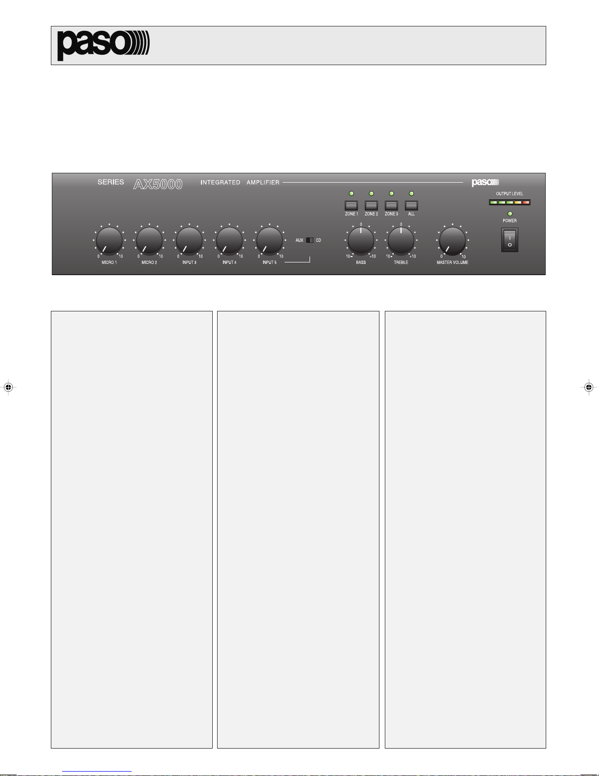
1.1 PANNELLO FRONTALE
Selettori delle zone.
[1]
[2] Visualizzatore del livello di uscita.
[3] Spia daccensione.
[4] Interruttore di rete.
[5] Controllo di volume generale.
[6] Controlli di tono.
[7] Selettore ingressi ausiliari.
[8] Controllo livello ingresso ausiliario.
[9] Controlli di livello ingressi 3 e 4.
[10] Controlli di livello ingressi microfonici.
11 12 15 16 17 18 1913 14
INTEGRATED AMPLIFIER
INPUT 3 INPUT4MICRO 1 MICRO 2
INPUT 5
ZONE 1 ZONE 3ZONE 2 ALL
AUX CD
0
101010101010 00000
BASS
0
10
+10
TREBLE
+10
1.1 FRONT PANEL
Zone selection switches.
[1]
[2] Output level indicator.
[3] ON/OFF signalling lamp.
[4] Mains switch.
[5] General volume control.
[6] Tone controls.
[7] Auxiliary inputs selector switch.
[8] Auxiliary input level control.
[9] Inputs 3 and 4 level control.
Level control for microphone inputs.
[10]
0
MASTER VOLUME
OUTPUT LEVEL
POWER
10
456910 8 7 3
8
W
1V 1W
W
8
W
GCOMHOT
LINK
PRE OUT
POWER IN
FUSE T6,3A
CONSUMPT. 200 W
CONSUM T. 200 W
600
MOHOUTPUT TEL
COM COMCOM V INZ2 Z3Z1
24V COM 50V 70V 100V
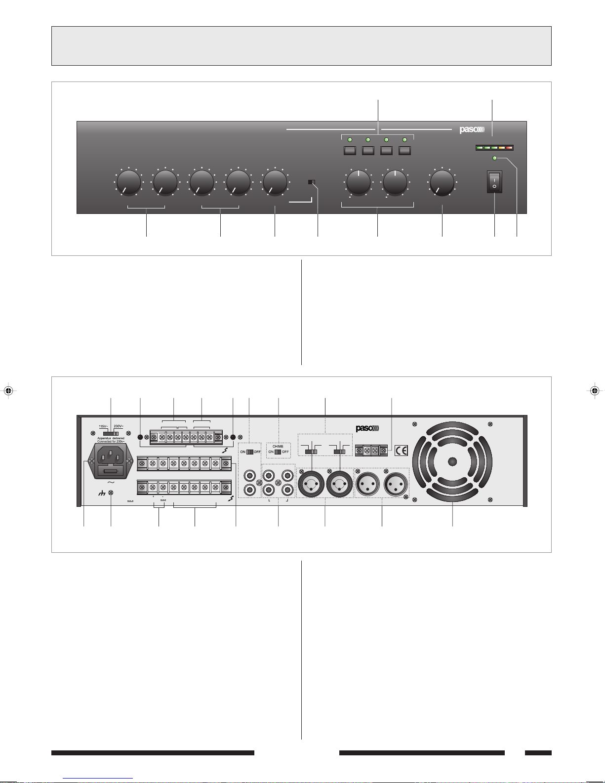
1.2 PANNELLO POSTERIORE
Selettore della tensione di rete.
[11]
[12] Regolazione livello uscita MUSIC ON HOLD.
[13] Uscite di linea e di potenza (1W/8Ω) MUSIC ON HOLD.
[14] Ingresso telefonico bilanciato.
[15] Regolazione livello ingresso telefonico.
[16] Presa per equalizzatore esterno.
[17] Chime ON/OFF.
[18] Selettori modalità funzionamento ingressi 3 e 4.
Morsettiera per contatto di precedenza.
[19]
[20] Presa di aerazione ventola di raffreddamento.
[21] Ingressi microfonici bilanciati.
[22] Ingressi MIC/LINE.
[23] Ingressi ausiliari.
Morsettiera per zone selezionate.
[24]
[25] Morsettiera uscite altoparlanti.
[26] Morsettiera per alimentazione esterna in corrente continua.
[27] Connessione telaio.
[28] Spina di rete con fusibile incorporato.
+
PRIORITY
S.p.A. -ITALY
P
AMPLIFIER
AX5120
LINE
AUX CD
INPUT 5 INPUT 4 INPUT 3 MICRO 2 MICRO 1
PHANTOM
PHANTOM
MIC
MIC
LINE
1.2 REAR PANEL
Mains voltage selector switch.
[11]
[12] MUSIC ON HOLD output level adjustment.
[13] MUSIC ON HOLD line and power outputs (1W/8Ω).
[14] Balanced telephone input.
[15] Telephone input level adjustment.
[16] Socket for an external equaliser.
[17] Chime ON/OFF.
[18] Inputs 3 and 4 mode selector switches.
Terminal strip for precedence contact.
[19]
[20] Cooling fan air intake.
Balanced microphone inputs.
[21]
[22] MIC/LINE inputs.
[23]
Auxiliary inputs.
[24] Terminal strip for selected zones.
[25] Loudspeaker output terminal strip.
[26] Terminal strip for external DC power supply.
[27] Frame connection.
[28] Mains plug with built-in fuse.
202122232425262728
SERIE 5000
3
GENERAL WARNINGS2AVVERTENZE GENERALI
2.1 INSTALLAZIONE
Tutti gli apparecchi PASO sono costruiti nel rispetto delle più severe
normative internazionali di sicurezza ed in ottemperanza ai requisiti
della Comunità Europea. Per un corretto ed efficace uso dellapparecchio
è importante prendere conoscenza di tutte le caratteristiche leggendo
attentamente le presenti istruzioni ed in particolare le note di sicurezza.
Durante il funzionamento dellapparecchio è necessario assicurare
unadeguata ventilazione. Evitare di racchiudere lapparecchio in un
mobile privo di aerazione o di ostruire le fessure di ventilazione ed in
particolare la presa daria posteriore della ventola di raffreddamento.
Evitare inoltre di tenere lapparecchio in prossimità di sorgenti di calore.
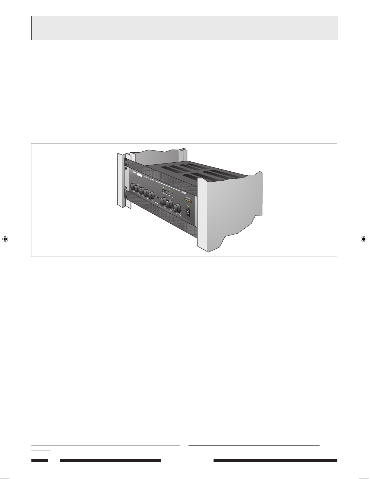
Questo apparecchio è predisposto per il montaggio in mobile rack standard
19 tramite luso dellaccessorio opzionale AC55.
Si consiglia di interporre un pannello di aerazione tra un apparecchio e
laltro (vedi fig. 2.1.1).
2.1 INSTALLATION
All PASO equipment is manufactured in accordance with the most
stringent international safety standards and in compliance with European
Community requisites. In order to use the equipment correctly and
effectively, it is important to be aware of all its characteristics by reading
these instructions and in particular the safety notes carefully.
While the equipment is working, it is necessary to provide adequate
ventilation. Do not close this equipment inside an unventilated cabinet
and do not obstruct the air vents, in particular not the air intake on the
rear for the cooling fan.
Do not keep the equipment in the vicinity of sources of heat.
This equipment can be equipped for mounting in a standard 19 by
means of the optional accessory AC55.
It is recommended that you place a ventilation panel between one
piece of equipment and the next (see Figure 2.1.1).
Fig. 2.1.1
2.2 ALIMENTAZIONE
Questo apparecchio è predisposto per il funzionamento con tensione di
rete a 230 V ± 10% 50/60 Hz. È possibile utilizzare lapparecchio anche
con una tensione di rete di 115 V ± 10% 50/60 Hz; a tal scopo è
necessario portare il selettore [11] in posizione 115 V.
Gli amplificatori della Serie 5000 possono anche essere alimentati con
una sorgente esterna di corrente continua con tensione di 24V che
deve essere applicata, rispettando le polarità, ai relativi terminali della
morsettiera [26]. In accordo con le normative di sicurezza, linterruttore
di accensione [4] agisce solo sulla tensione di rete.
In dotazione allapparecchio é fornito un cavo di alimentazione con filo
di terra; il terminale di terra della spina di rete non deve essere rimosso
in alcun caso.
Collegare la spina di rete [28] dellapparecchio alla rete elettrica
utilizzando lapposito cavo fornito in dotazione; assicurarsi che la presa
di corrente sia dotata di collegamento di terra a norma di legge.
Lapparecchio è protetto da due fusibili (vedi par. 4.4).
2.3 NOTE DI SICUREZZA
Ogni intervento allinterno dellapparecchio, quale la selezione di alcuni
modi duso o la sostituzione di fusibili, deve essere effettuato solo da
personale specializzato: la rimozione del coperchio rende accessibili
parti con rischio di scosse elettriche.
Prima di rimuovere il coperchio accertarsi sempre che il cavo di rete sia
staccato.
Nel caso di accidentale caduta di liquidi sullapparecchio, staccare
immediatamente la spina di rete ed interpellare il centro di assistenza
PASO più vicino.
La connessione di telaio [27] consente di collegare altre apparecchiature
per la sola funzione di schermatura dei segnali a basso livello:
presa non deve essere utilizzata per il collegamento di sicurezza del telaio
alla terra.
questa
2.2 POWER SUPPLY
This equipment is designed for use with a mains voltage of 230 V ± 10%
50/60 Hz. It is also possible to use the equipment with a mains voltage
of 115 V ± 10% 50/60 Hz, however in this case it is necessary to
position the selector switch [11] on 115 V.
The amplifiers of the 5000 Series can also be powered by means of an
external DC power supply with a voltage of 24V, which has to be applied
to the appropriate terminals on the terminal strip [26] paying attention
to the correct polarity. As required under safety regulations, the
ON/OFF switch [4] only controls the mains voltage.
The equipment is supplied with its own power-supply cable, which is
equipped with an earthing wire. The earth terminal of the mains plug
should never be removed under any circumstances.
Connect the mains plug [28] of the equipment to the power mains using
the cable included in the supply. Make sure that the power outlet is
equipped with a connection to earth in accordance with the law.
The equipment is protected by two fuses (see point 4.4).
2.3 SAFETY NOTES
Any activities inside the apparatus, such as selecting some of the
operating modes, the installation of accessories or the replacement
of fuses, must be carried out by specialized personnel only: when the
cover is removed, parts liable to cause electric shocks are exposed.
Before removing the cover, always make sure that the power cord
has been disconnected.
In the event that liquid is accidentally spilt onto the apparatus,
disconnect the mains plug immediately and contact the nearest PASO
Service Centre.
The chassis connection [27] may be used to connect other equipment
only for the purpose of shielding the low signals:
be used to connect the chassis to earth for safety purposes.
this socket may not
4
SERIE 5000
CONNECTIONS3CONNESSIONI
3.1 CRITERI GENERALI
Per un corretto funzionamento dellapparecchio è opportuno osservare
alcuni criteri di massima nellesecuzione dei collegamenti:
evitare il posizionamento di cavi e di microfoni sul mobile
dellapparecchio.
evitare di stendere le linee di segnale parallele a quelle di rete;
osservare una distanza minima di 30/40 cm.
posizionare le linee di ingresso e le linee di uscita distanti tra loro.
posizionare i microfoni al di fuori dellangolo di radiazione dei diffusori
sonori per evitare il fenomeno di reazione acustica (effetto Larsen).
3.2 INGRESSI MICROFONICI
Alle prese XLR MICRO 1 e MICRO 2 [21] è possibile collegare
microfoni PASO di tipo dinamico e ad elettrete con alimentazione phantom;
i collegamenti a queste prese sono riportati nella Fig. 3.2.1.
Ulteriori possibilità di connessione, che sfruttano luso della morsettiera
PRIORITY [19], sono riportate al par. 3.7.
Ogni ingresso microfonico dispone di un proprio controllo di livello [10]
per dosare opportunamente lampiezza dei vari segnali.
Lingresso microfonico MICRO 1 dispone, inoltre, della funzione di
precedenza automatica (VOX): parlando al microfono collegato a questo
ingresso verranno automaticamente ammutoliti gli ingressi ausiliari e
lingresso INPUT 4 (se selezionato, vedi par. 3.3); il livello della soglia
di attivazione del circuito di precedenza automatica non è dipendente
dalla posizione del controllo MICRO 1 [10].
Gli ingressi microfonici [21] sono dotati di alimentazione Phantom per
microfoni elettrete 12/24V.
In caso si volesse disinserire lalimentazione Phantom, agire sui ponticelli
SW201 - SW202 situati sul circuito ingressi (vedi par. 2.3).
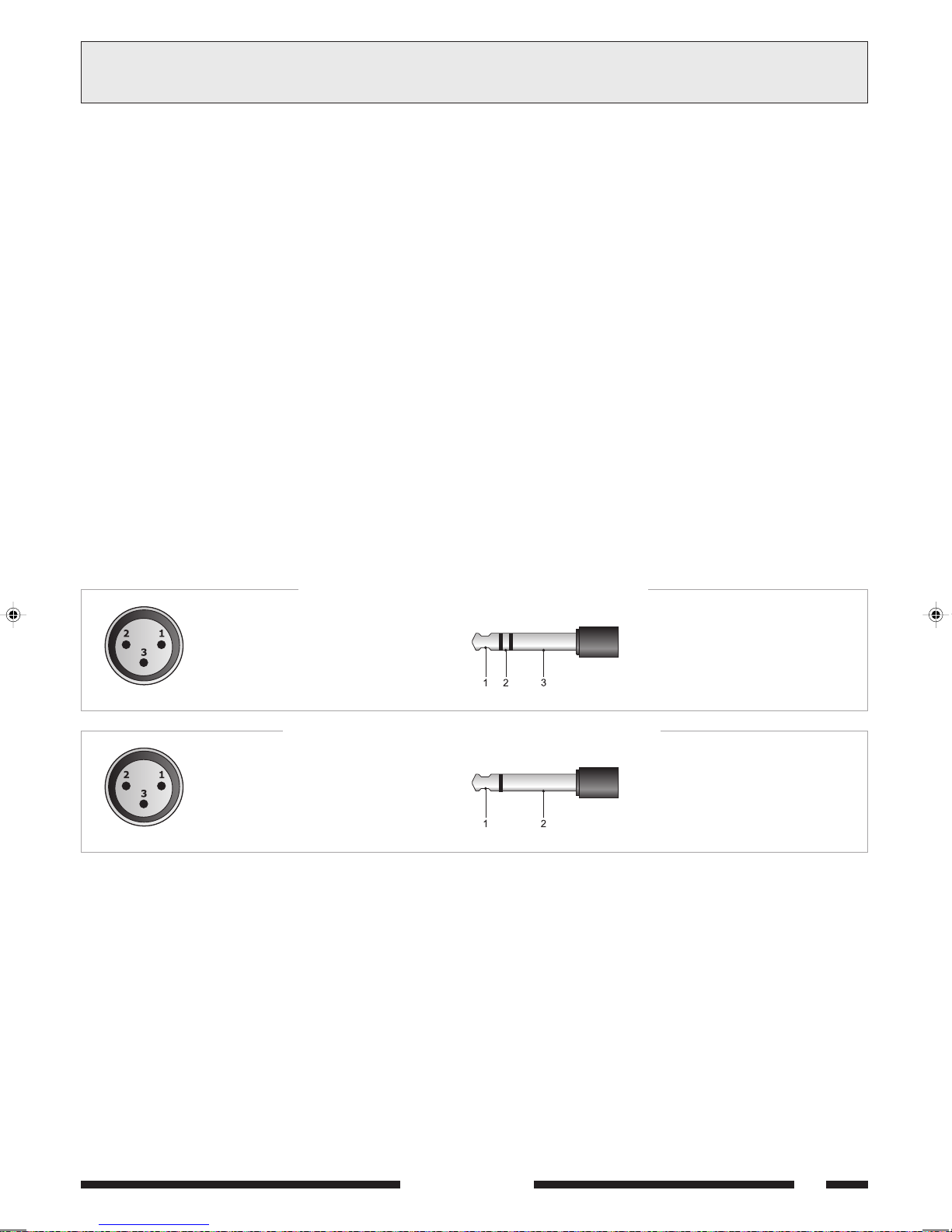
COLLEGAMENTO BILANCIATO - BALANCED CONNECTION
3.1 GENERAL FEATURES
For proper unit operation, use the following instructions when making
the connections:
Do not place cables or microphones on the unit cabinet;
Do not lay signal lines parallel to power lines; ensure a minimum
distance of 30/40 cm between them;
Keep input lines and the output lines far apart;
Keep the microphones outside the operating span of the speakers to
avoid acoustic feedback (Larsen effect).
3.2 MICROPHONE INPUTS
It is possible to connect PASO microphones of the dynamic or of the electret
type with a phantom power supply to the XLR sockets MICRO 1 and
MICRO 2 [21].
The connections to these sockets are shown in Figure 3.2.1.
Further possible connections exploiting the PRIORITY terminal strip
[19] are indicated under point 3.7.
Each microphone input has its own level control [10] so that the
amplitude of the various different signals can be suitably adjusted.
The MICRO 1 microphone input also has an automatic priority
function (VOX). When speaking with the microphone connected to this
input, the auxiliary inputs and INPUT 4 will be automatically muted
(if selected, see point 3.3). The level of the threshold for activating
the automatic priority circuit does not depend on the position of the
MICRO 1 control [10].
The microphone inputs [21] have a phantom power supply for 12/24V
electret microphones. To exclude the phantom power supply, use
jumpers SW201 and SW202 on the input circuit (see point 2.3).
1 = schermo / shield
2 = segnale (lato caldo) / signal (hot side)
3 = segnale (lato freddo) / signal (cold side)
COLLEGAMENTO SBILANCIATO - UNBALANCED CONNECTION
1 = schermo e massa / shield and GND
2 = schermo e massa / shield and GND
3 = segnale / signal
Fig. 3.2.1
3.3 INGRESSI MIC/LINE
Le prese INPUT 3 ed INPUT 4 [22] sono configurabili in modo
indipendente come ingressi microfonici (con o senza alimentazione
phantom) o come ingressi di linea. La selezione della modalità è ottenuta
tramite i deviatori a tre posizioni [18]:
in posizione MIC, si seleziona la sensibilità microfonica con alimentazione
phantom disattivata;
in posizione PHANTOM, si seleziona la sensibilità microfonica attivando
lalimentazione phantom (per microfoni elettrete 12/24V);
in posizione LINE, si seleziona la sensibilità di linea.
É possibile effettuare il collegamento sia con spine di tipo XLR maschio che
con spinotto jack 1/4. I collegamenti a queste prese sono riportati
nella Fig. 3.2.1.
Ogni ingresso dispone di un proprio controllo di livello [9] per dosare
opportunamente lampiezza dei vari segnali.
Lingresso INPUT 4 può essere assoggettato o meno alla precedenza
automatica (VOX) dellingresso MICRO 1 ed alla chiusura del contatto
di precedenza PRIORITY. In caso si volesse disinserire questa funzione,
agire sul ponticello SW207 posto sul circuito ingressi (vedi par. 2.3).
1 = segnale (lato caldo) / signal (hot side)
2 = segnale (lato freddo) / signal (cold side)
3 = schermo / shield
1 = segnale / signal
2 = schermo e massa / shield and GND
3.3 MIC/LINE INPUTS
The INPUT 3 and INPUT 4 sockets [22] can be separately
configured as microphone inputs (with or without phantom power supply)
or as line inputs.
The modes are selected by means of the three-position switches [18]:
in the MIC position the sensitivity of the microphone with the phantom
power supply de-activated is selected;
in the PHANTOM position the sensitivity of the microphone with the
phantom power supply activated (for 12/24V electret microphones) is
selected;
in the LINE position the sensitivity of the line is selected.
It is possible to make the connections either with male XLR plugs or with
1/4 jacks. The connections to these sockets are shown in Figure 3.2.1.
Each input has its own level control [9] so as to be able to adjust the
amplitude of the various different signals suitably.
INPUT 4 can be subjected or otherwise to automatic priority (VOX) on
the part of the MICRO 1 input and to closing of the PRIORITY contact.
In the event that you wish to de-activate this function, use jumper
SW207 situated on the input circuit (see point 2.3).
SERIE 5000
5
3CONNESSIONI
CONNECTIONS
3.4 INGRESSI AUSILIARI
Alle prese phono AUX e CD [23] è possibile collegare due sorgenti
musicali ad alto livello (lettore di compact disc, riproduttore a nastro,
sintonizzatore, radioricevitore per microfoni senza filo, ecc.).
La doppia presa consente un veloce collegamento della sorgente
allamplificatore tramite cavetto stereo: la miscelazione dei due canali
destro e sinistro (L/R) è realizzata internamente.
La selezione della sorgente avviene tramite lapposito selettore [7] posto
sul pannello frontale dellapparecchio.
La regolazione di livello della sorgente selezionata si effettua tramite il
controllo INPUT 5 [8].
La sorgente selezionata è soggetta allammutolimento sia per precedenza
automatica (VOX) degli ingressi TEL e MICRO 1 che per la chiusura del
contatto PRIORITY.
3.5 INGRESSO TELEFONICO
Lapparecchio è predisposto per il collegamento ad un sistema telefonico
tramite la morsettiera TEL [14]. Tale ingresso è bilanciato a
trasformatore, possiede un proprio controllo di livello - LEV. [15] - ed è
dotato di circuito VOX per la diffusione dei messaggi con priorità più
elevata rispetto a qualsiasi altro ingresso.
Lingresso telefonico consente inoltre il collegamento dellapparecchio alle
basi preamplificate PASO mod. B611. Per questo è necessario rimuovere
lo spinotto pentapolare DIN dal cavo della base e con i fili realizzare i
collegamenti illustrati in fig. 3.5.1.
IMPORTANTE: per questo tipo di collegamento è INDISPENSABILE
chiudere tramite un ponticello i contatti [G] e [COM] della morsettiera
TEL [14].
3.4 AUXILIARY INPUTS
It is possible to connect two high-level sources of music (CD player, tape
recorder, tuner, radio-receiver for wireless microphones, etc.) to the
AUX and CD [23] phono sockets. Thanks to the fact that there are
two sockets, it is easy to connect the source rapidly to the amplifier by
means of a stereo cable: mixing of the two channels (left and right - L/R)
is carried out internally.
The source is selected by means of the selector [7] provided for this
purpose on the front panel of the equipment.
The level of the source that is selected can be adjusted by means of the
INPUT 5 control [8].
The source that is selected is subject to muting both as a result of
automatic priority (VOX) of the TEL and MICRO 1 inputs and due to
closing of the PRIORITY contact.
3.5 TELEPHONE INPUT
The equipment has provisions for connection of a telephone system by
means of the TEL terminal strip [14].
This input is balanced by a transformer, has its own level control - LEV.
[15] - and is equipped with a VOX circuit for broadcasting messages with
a higher priority level than any other input.
The telephone input also enables the equipment to be connected to the
PASO mod. B611 pre-amplified bases. To do this, it is necessary to
remove the five-pole DIN plug from the cable on the base and use the
wires to make the connections illustrated in Figure 3.5.1.
IMPORTANT: For this type of connection it is ESSENTIAL to close the
contacts [G] and [COM] of the TEL terminal strip [14] with a jumper.
FUSE T6,3A
CONSUMPT. 200W
CONSUM T. 200 W
8
W
1V 1W
8
W
GCOMHOT
600
W
MOH OUTPUT TEL
COM COMCOM V INZ2 Z3Z1
24 V COM 50V 70 V 100V
.SOP
1 OMREHCS DLEIHS
2 OREN KCALB [ MOC ]
3 OCNAIB ETIHW [ TOH ]
4 OSSOR DER
5 EDREV NEERG [P]
LINK
PRE OUT
POWER IN
OVAC
AMPLIFIER
AUX CD
INPUT 5 INPUT4 INPUT 3 MICRO 2 MICRO 1
ELBAC
AX5120
PHANTOM
MIC
LINE
PHANTOM
LINE
AREITTESROM
PIRTSLANIMRET
MIC
[G]
"LET"
"YTIROIRP"
[+]
+
PRIORITY
S.p.A. - ITALY
P
ELANIMRET
LANIMRET
1
2
3
4
5
6
Fig. 3.5.1
SERIE 5000

3CONNESSIONI
CONNECTIONS
3.6 USCITA MUSIC ON HOLD (MOH)
A questi morsetti [13] e' disponibile il segnale della sola sorgente
selezionata sull INPUT 5 [7] ; tale segnale non e' soggetto allazione di
precedenza microfonica o telefonica. In particolare, l'uscita bilanciata a
trasformatore (morsetti 1-2-3 di fig. 3.6.1) puo' essere utilizzata per il
pilotaggio di un ulteriore amplificatore, di un centralino telefonico od
altro; l'uscita di potenza (morsetti 3-4 di fig. 3.6.1) e' in grado di pilotare
direttamente un piccolo altoparlante monitor da 8 Ω con potenza massima
di 1 W.
É possibile regolare il livello di uscita agendo sul controllo LEV. [12].
1: 600Ω (linea - lato caldo)
(line - warm side)
2: 600Ω (linea - lato freddo)
(line - cold side)
3: massa e schermo
GND and shield
4: 1W/8Ω uscita altoparlanti
loudspeakers output
Fig. 3.6.1
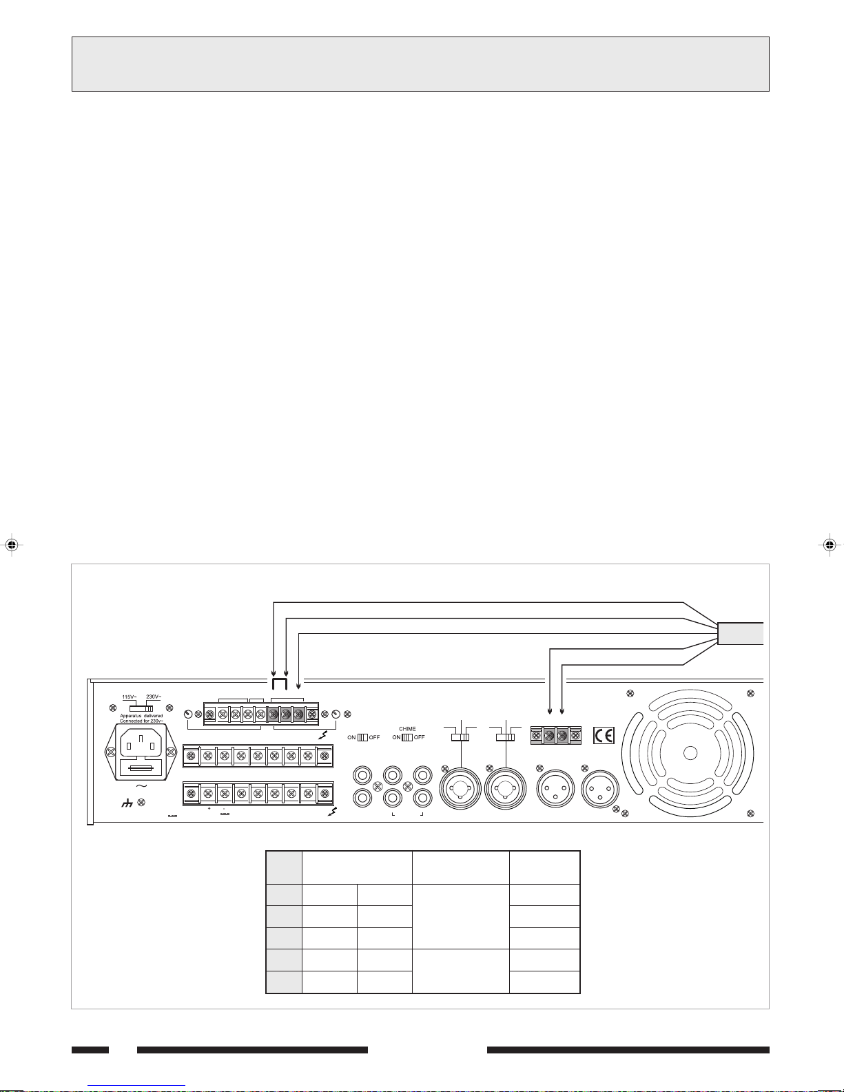
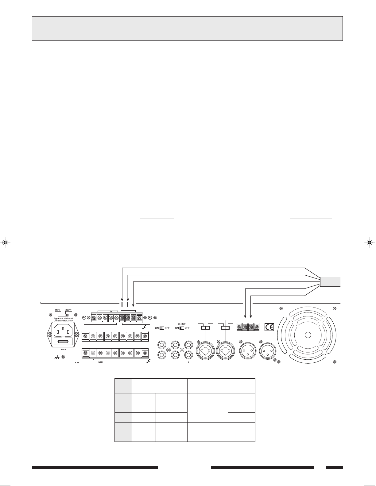
3.7 PRECEDENZA MICROFONICA E SEGNALE DI PREAVVISO
Chiudendo i contatti della morsettiera PRIORITY [19] vengono
ammutoliti la sorgente musicale selezionata e lingresso INPUT 4 (vedi
par. 3.3); la chiusura del contatto genera un segnale di preavviso a due
toni (CHIME) quando il selettore CHIME [17] si trova in posizione ON.
É possibile modificare il livello del segnale di preavviso agendo sul trimmer
semifisso VR301 posto sul circuito Priority (vedi par. 2.3).
Per sfruttare efficacemente la funzione di precedenza è possibile
utilizzare il microfono PASO mod. M906 e le basi B501-M e B601 (le
basi nel numero massimo di due). In fig. 3.7.1 è riportato un esempio di
collegamento di una base B601.
3.6 MUSIC ON HOLD OUTPUT (MOH)
The signal only of the source selected on INPUT 5 [7] is available on
these terminals [13]. This signal is not affected by the use of telephone
precedence. In particular, the balanced transformer output (strips 1-23, Fig. 3.6.1) can be used to drive an additional amplifier, a telephone
exchange or other equipment. The power output (terminals 3-4 in Figure
3.6.1) is capable of driving directly a small 8 Ω monitoring loudspeaker
with a maximum output of 1 W.
It is possible to adjust the output level by means of the LEV.
control [12].
5: TEL (massa schermo)
(
GND and shield)
6: TEL (ingresso - lato freddo)
(input - cold side)
7: TEL (ingresso - lato caldo)
(input - warm side)
3.7 MICROPHONE PRIORITY AND WARNING SIGNAL
On closing the contacts of the PRIORITY terminal strip [19] the
music source that has been selected and INPUT 4 (see point 3.3) are
muted. Closing the contact causes a two-tone warning signal (CHIME)
to be generated if the CHIME selector [17] is in the ON position.
It is possible to alter the level of the warning signal by means of the
semi-fixed trimmer VR301 situated on the Priority circuit (see point 2.3).
In order to exploit the priority function effectively, it is possible to use
a mod. M906 PASO microphone and the PASO B501-M and B601
bases (a maximum of two bases). Figure 3.7.1 shows an example of
connection of a B601 base.
FUSE T6,3A
CONSUMPT. 200 W
CONSUM T. 200 W
8
W
600
MOHOUTPUT TEL
COM COMCOM VINZ2 Z3Z1
24V COM 50 V 70 V 100V
GCOMHOT
1V 1W
W
8
W
B601
LEV.LEV.
LINK
PRE OUT
POWER IN
BIANCO / WHITE VERDE / GREEN
+
PRIORITY
S.p.A. -ITALY
P
AMPLIFIER
AX5120
LINE
AUX CD
INPUT 5 INPUT 4 INPUT 3 MICRO 2 MICRO 1
PHANTOM
PHANTOM
MIC
MIC
LINE
Fig. 3.7.1
SERIE 5000
7
3CONNESSIONI
CONNECTIONS
3.8 USCITE DI POTENZA
Le uscite di potenza per i diffusori sono disponibili sulla morsettiera [25].
È possibile realizzare un impianto di diffusione sonora utilizzando sia
diffusori a bassa impedenza, sia diffusori dotati di traslatore di linea.
In entrambi i casi il carico complessivo non deve essere tale da
sovraccaricare lamplificatore: non applicare cioè diffusori o gruppi di
diffusori con impedenza più bassa di quella nominale della presa alla
quale sono collegati. Si raccomanda inoltre di porre particolare attenzione
al calcolo delle impedenze nel caso si debbano realizzare impianti di
diffusione misti (a bassa impedenza e a tensione costante).
In tabella 3.8.1 sono riportati i valori nominali di tensione ed impedenza
per le diverse uscite.
Uscita
8 Ω
50 V
70 V
100 V
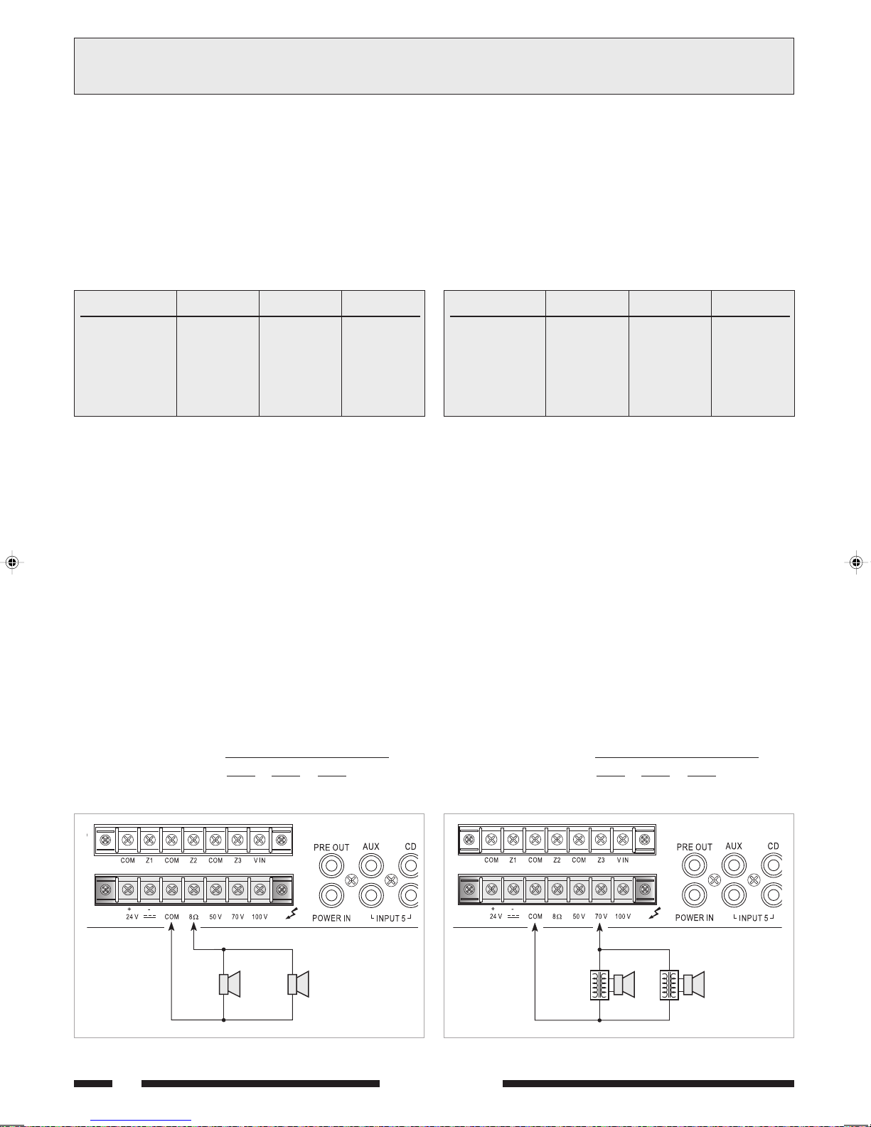
3.8.1 Sistemi a bassa impedenza
In applicazioni che richiedono luso di pochi altoparlanti, la linea di
collegamento può essere connessa tra il terminale comune 0 e la presa
ΩΩ
8
Ω della morsettiera [25].
ΩΩ
Il collegamento degli altoparlanti, di tipo serie o parallelo o misto, deve
fornire unimpedenza calcolata pari o superiore ad 8 Ω.
In figura 3.8.1 é riportato un esempio di collegamento.
AX5240
43,8 V
10,4 Ω
20,4 Ω
41,7 Ω
Tabella 3.8.1
AX5120
31 V
20,8 Ω
40,8 Ω
83,3 Ω
AX5060
21,9 V
41,7 Ω
81,6 Ω
167 Ω
3.8 POWER OUTPUTS
The power outputs for the loudspeakers are available on the terminal
strip [25]. It is possible to set up a sound-broadcasting system
using either low-impedance loudspeakers or loudspeakers equipped with
a line transformer. In both cases the overall load must not be such as to
overload the amplifier. This means that you must not apply loudspeakers
or groups of loudspeakers with an impedance lower than the rated
impedance of the socket to which they are connected. It is also
necessary to pay particular attention to calculating the impedance values
if mixed broadcasting systems (low impedance and constant voltage)
are to be set up. Table 3.8.1 shows voltage and impedance rated values
for the various outputs.
Output
8 Ω
50 V
70 V
100 V
3.8.1 Low-impedance systems
In applications that require the use only of a few loudspeakers, the
connecting line may be connected between the common terminal 0 and
ΩΩ
the 8
Ω socket of the terminal strip [25].
ΩΩ
The loudspeaker connection, whether of the serial or parallel type or
mixed, should provide an impedance calculated to be equal to or higher
than 8 Ω. An example of a connection is shown in Figure 3.8.1.
AX5240
43,8 V
10,4 Ω
20,4 Ω
41,7 Ω
Table 3.8.1
AX5120
31 V
20,8 Ω
40,8 Ω
83,3 Ω
AX5060
21,9 V
41,7 Ω
81,6 Ω
167 Ω
Calcolo dellimpedenza nei collegamenti in serie
Nel caso di diffusori collegati in serie tra loro, limpedenza totale è la
somma delle singole impedenze:
impedenza totale = Z1 + Z2 + Z3 + ....
Calcolo dellimpedenza nei collegamenti in parallelo
Nel caso di diffusori collegati in parallelo tra loro, limpedenza totale può
essere determinata mediante la seguente formula:
impedenza totale =
1
+
Z11 Z2
ΩΩ
Ω
ΩΩ
1
1
+ + ......
Z3
ΩΩ
16
Ω16
ΩΩ
Calculating the impedance value in series connections
In the case of loudspeakers connected to one another in series, the total
impedance is the sum of the single impedance values:
Total impedance = Z1 + Z2 + Z3 + ....
Calculating the impedance value in parallel connections
In the event of loudspeakers connected in parallel to one another the
total impedance can be calculated by means of the following formula:
Total impedance =
1
+
Z11 Z2
1
1
+ + ......
Z3
Fig. 3.8.1
8
20W 20W
Fig. 3.8.2
SERIE 5000

3CONNESSIONI
f
where the amplifier rated impedance may be determined referring to
Table 3.8.1.
Example: If a AX5240 amplifier is used with speakers type Paso C55
having a 500 ohm impedance, the rated load impedance of the
line at 100 V may be determined from Table 3.8.1 as being equal to
41,7 ohm.
Thus
CONNECTIONS
3.8.2 Sistemi a tensione costante
Nel caso di impianti con un gran numero di diffusori e/o con distanze tra
amplificatori ed altoparlanti molto elevate é preferibile utilizzare un sistema
di distribuzione a tensione costante (definito anche ad alta impedenza).
In questo tipo di impianto, i diffusori, provvisti di trasformatori di
adattamento di impedenza, sono tutti collegati in derivazione alla linea
(vedi es. di Fig. 3.8.2); questo particolare rende di facile realizzazione
limpianto e, nel caso in cui un altoparlante dovesse per qualche motivo
scollegarsi dalla linea, il resto dellimpianto proseguirebbe nel suo regolare
funzionamento. Le tensioni costanti disponibili in uscita dallamplificatore
sono 50, 70 e 100 V.
Calcolo del numero di diffusori (tramite le potenze)
Si supponga di avere definito sia l'amplificatore (cioè la sua potenza di
uscita) che il tipo di diffusore con relativa potenza assorbita.
In questo caso il massimo numero di diffusori collegabile sulla linea è
determinato dalla seguente formula:
numero diffusori =
Esempio: si utilizzino un amplificatore AX5240 con plafoniere modello
Paso C42. L'amplificatore è in grado di erogare una potenza pari a
240 W, mentre un diffusore assorbe una potenza di 6 W.
Per sapere quanti diffusori sono collegabili alla linea di uscita si calcola:
numero diffusori = = 40
Calcolo del numero di diffusori (tramite le impedenze)
Se il dato disponibile è l'impedenza del diffusore, il numero massimo di
diffusori collegabili ad una linea è:
numero diffusori =
dove l'impedenza nominale dell'amplificatore è ricavabile dalla
tabella 3.8.1.
Esempio: si utilizzino un amplificatore AX5240 con diffusori tipo
Paso C55, che presentano una impedenza pari a 500 ohm.
Dalla tabella 3.8.1 si trova che l'impedenza nominale di carico della linea
a 100 V è pari a 41,7 ohm.
Quindi:
numero diffusori = = 12
potenza amplificatore
potenza diffusore
240 W
6 W
impedenza diffusore
impedenza amplificatore
500 Ω
41,7 Ω
3.8.2 Constant voltage systems
When a large number of speakers is used and/or the speakers are
placed far from the amplifiers, constant voltage distribution system
should be used (also known as high-impedance systems).
In this type of system, the speakers are fitted with impedance
adaptation transformers and all of them have shunt line connections
(see example of Fig. 3.8.2). This simplifies the layout of the system and
if, for any reason, a loudspeaker is disconnected from the line, the rest
of the system will continue to work properly. The constant voltages
output from the amplifier are 50, 70 and 100 V.
Determining the number of speakers (through power values)
If both the amplifier (i.e. its output power) and the type of speaker
with its power consumption have been established, the maximum number
of speakers which may be connected to the line may be determined as
follows:
number of speakers =
Example: in a system including a AX5240 amplifier with ceiling speakers
type Paso C42 is used, the amplifier can supply 240 W power whereas
the speaker has a power consumption of 6 W.
The number of speakers which may be connected to the output line is
number of speakers = = 40
Determining the number of speakers (through impedance)
If the impedance of the speaker is known, the maximum number o
speakers which may be connected to the line is:
number of speakers =
number of speakers = = 12
amplifier power
speaker power
240 W
6 W
speaker impedance
amplifier impedance
500 Ω
41,7 Ω
NOTA BENE: nel caso più generale in cui i diffusori sono di diverso tipo
e/o collegati con differente potenza, è importante verificare sempre che
la potenza complessiva richiesta dai diffusori (ottenuta semplicemente
dalla somma delle singole potenze) sia inferiore a quella nominale
dellamplificatore.
3.9 USCITA REGISTRATORE/BOOSTER E PRESA EQUALIZZATORE
Nei casi in cui fosse richiesta una elaborazione acustica del segnale, è
possibile collegare un equalizzatore, od altro elaboratore di segnale, alle
prese POWER IN e PRE OUT [16] dellapparecchio. Per l'inserzione
dell'equalizzatore, l'interrutore LINK posto sul retro dell'apparecchio deve
essere nella posizione OFF. Questa realizzazione permette la correzione
acustica di ambienti particolarmente riverberanti e la soppressione della
retroazione acustica diffusore-microfono (effetto Larsen).
Se all'amplificatore non sono collegate, tramite le prese POWER IN e
PRE OUT, apparecchiature esterne, l'interruttore LINK deve essere
posto in posizione ON per mantenere la continuità della catena
amplificatrice.
Alla presa di uscita PRE OUT è disponibile il segnale di pilotaggio della
parte di potenza costituito dalla miscelazione delle diverse sorgenti prima
del controllo di volume generale MASTER VOLUME [5]. Tale segnale
può essere utilizzato per il pilotaggio di unità di potenza e/o inviato ad
una piastra di registrazione.
N. B.: In the more general case of a system including loudspeakers of
different types or connected with different outputs, it is always important
to make sure that the overall power required by the loudspeakers (which
can be calculated simply by adding up the output power of the single
units) is lower than the rated power of the amplifier.
3.9 RECORDER /BOOSTER OUTPUT AND EQUALISER SOCKET
In those cases in which acoustic processing of the signal is required, it
is possible to connect an equaliser or other signal processing equipment
to the POWER IN and PRE OUT sockets [16] on the equipment.
When inserting the equaliser, the LINK switch on the rear of the
equipment must be in the OFF position. This application enables acoustic
correction of rooms subject to particularly severe reverberation and
the suppression of acoustic feedback between loudspeakers and
microphones (Larsen effect).
If no external equipment is connected to the amplifier by means of the
POWER IN and PRE OUT sockets, the LINK switch must be in the ON
position in order to maintain continuity of the amplifier chain.
The signal driving the power part consisting of the signal resulting from
the mixing of the various sources before the MASTER VOLUME control
[5] is available on the PRE OUT output socket. This signal can be used
to drive power units and/or sent to a recording deck.
SERIE 5000
9
3CONNESSIONI
C
R
CONNECTIONS
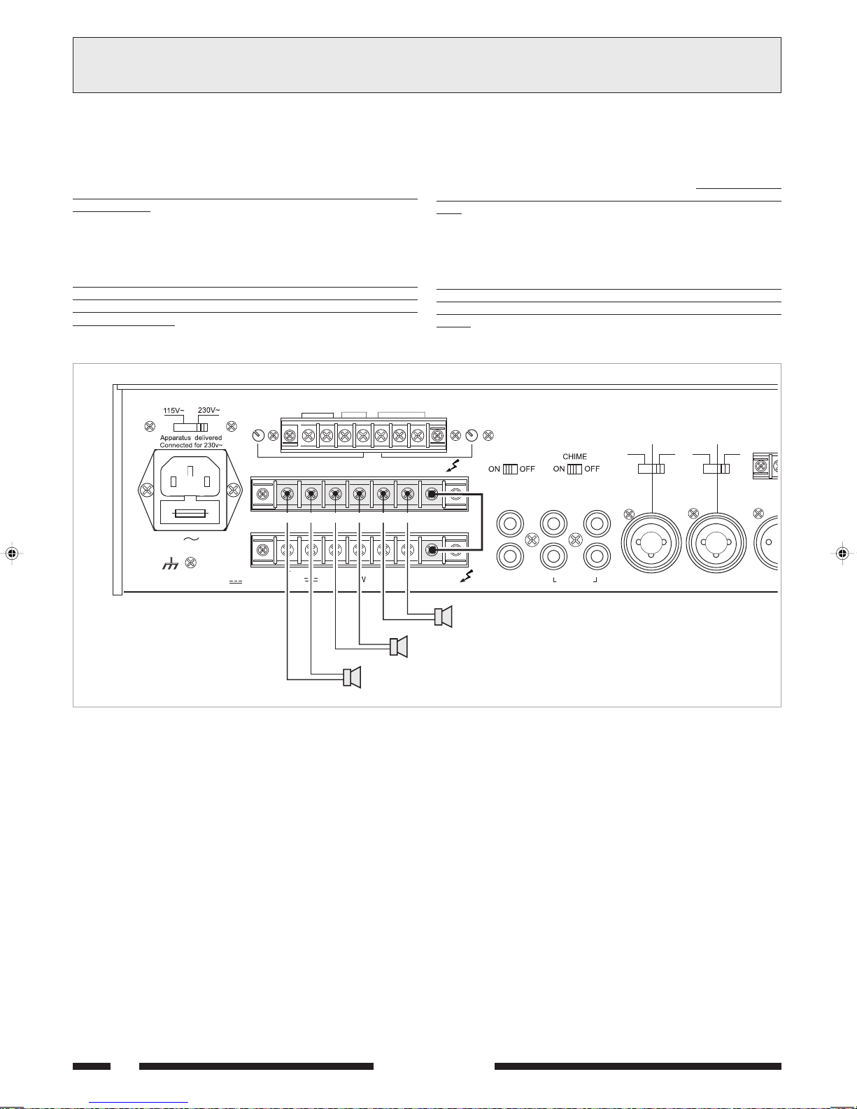
3.10 SELEZIONE DI ZONE DASCOLTO
Gli amplificatori della Serie 5000 dispongono della possibilità di
inserire/disinserire in modo indipendente fino a tre zone di diffusione
tramite gli interruttori ZONE 1, ZONE 2 e ZONE 3 [1]. In questo caso,
le tre zone di diffusori devono essere connesse alla morsettiera [24],
tenendo sempre conto del carico nominale massimo ammesso
dallapparecchio (vedi par. 3.8.2).
É inoltre possibile selezionare contemporaneamente tutte le zone dascolto
tramite linterruttore ALL. Le selezioni effettuate tramite gli interruttori
[1] sono confermate dallaccensione delle relative spie luminose.
Gli interruttori interrompono il collegamento delle linee a tensione
costante sui terminali della morsettiera [24].
La selezione della tensione di linea per le zone deve essere effettuata
collegando, tramite uno spezzone di filo, il terminale V IN della
morsettiera [24] al terminale corrispondente alla tensione desiderata
sulla morsettiera [25]. In fig. 3.10.1 è riportato un esempio di collegamento
a tre zone di diffusione con tensione di linea 100 V.
8
W
Z2
GCOMHOT
Z3
600
1V 1W
W
MOH OUTPUT TEL
COM COMCOM
Z1
FUSE T6,3A
CONSUMPT. 200 W
3.10 SELECTING THE LISTENING AREAS
With the amplifiers of the 5000 Series it is possible to include or
exclude up to three broadcasting areas separately, using the ZONE 1,
ZONE 2 and ZONE 3 switches [1]. In this case, the three loudspeaker
areas must be connected to the terminal strip [24],
always taking the
maximum permissible rated load for the equipment into account (see
point 3.8.2).
It is also possible to select all the listening areas at the same time by
means of the ALL switch. The selections made by means of the switches
[1] are confirmed by the relevant signalling lamps lighting up.
These switches cut off the constant voltage lines on the terminals of
the terminal strip [24].
The line voltage for the various zones has to be selected by connecting
the V IN terminal of the terminal strip [24] to the terminal corresponding
to the required voltage on the terminal strip [25] by means of a length
of wire. An example of connection to three broadcasting zones with a
line voltage of 100 V is shown in Figure 3.10.1.
LEV.LEV.
LINK
PRE OUT
VIN
AMPLIFIER
AUX CD
AX5120
PHANTOM
MIC
LINE
PHANTOM
LINE
MIC
P
CONSUM T. 200 W
24 V COM 50V 70 V 100 V
8
W
ZONE 2
ZONE 1
Fig. 3.10.1
ZONE 3
POWER IN
INPUT 5 INPUT 4 INPUT 3 MI
10
SERIE 5000

OPERATION4USO DELLAPPARECCHIO
4.1 ACCENSIONE
Prima di mettere in funzione l'apparecchio accertarsi di avere realizzato
tutte le connessioni necessarie al completamento dell'impianto e di aver
effettuato le impostazioni di funzionamento.
Portare l'interruttore di rete [4] in posizione ON.
La spia luminosa POWER [3] confermerà l'accensione dell'apparecchio.
Se necessario, regolare il livello di ascolto tramite il controllo MASTER
VOLUME [5] e ritoccare i livelli delle sorgenti sonore per una corretta
equalizzazione dei segnali tramite i controlli di livello [8], [9], [10] e [15].
4.2 CONTROLLO DI VOLUME PRINCIPALE
Il controllo di volume principale MASTER VOLUME [5] regola il livello
complessivo del segnale di uscita, derivato dalla miscelazione dei vari
segnali di ingresso. Per ottenere in uscita un segnale privo di distorsione,
si raccomanda di controllare che sull'indicatore del livello di uscita [2]
non si accenda la spia di colore rosso (+1 dB) o, comunque, che ciò
avvenga saltuariamente; in caso contrario, è necessario diminuire il
livello di uscita agendo sul comando MASTER VOLUME [5].
La potenza di uscita nominale è segnalata dall'accensione della spia
luminosa gialla (0 dB).
4.3 CORREZIONE ACUSTICA
I controlli BASS e TREBLE [6] modificano la tonalità del segnale di
uscita derivato dalla miscelazione dei vari segnali di ingresso.
Controllo toni bassi (BASS)
Il controllo BASS regola le prestazioni dell'amplificatore alle basse
frequenze. La posizione di centro, indicata dallo 0, fornisce una risposta
lineare; per avere una esaltazione delle frequenze basse ruotare la
manopola in senso ORARIO. Utilizzando diffusori a tromba è opportuno
tramite il comando BASS, attenuare le frequenze basse; un eccessivo
livello delle basse frequenze potrebbe danneggiare la membrana del
diffusore.
Controllo toni acuti (TREBLE)
Il controllo TREBLE regola le prestazioni acustiche dell'amplificatore alle
alte frequenze. La posizione di centro, indicata dallo 0, fornisce una
risposta di tipo lineare; per avere una esaltazione delle frequenze alte
ruotare la monopola in senso ORARIO. Lattenuazione dei toni acuti è
utlie per minimizzare un eccessivo livello di fruscio o per rendere più dolci
suoni particolarmente sibilanti.
4.1 POWER ON
Before starting up the equipment, make sure that all the connections
required for completing the system have been made and that all the
settings for correct operation have been made.
Set the mains switch [4] to the ON position.
The POWER [3] LED lights up, when the unit is switched on.
If necessary, adjust the listening level by means of the MASTER VOLUME
control [5] and adjust the levels of the sound sources for correct
equalisation of the signals by means of the level controls [8], [9], [10]
and [15].
4.2 MASTER VOLUME CONTROL
The MASTER VOLUME volume control [5] adjusts the output signal
overall level as generated by mixing different input signals.
To obtain a flutter-free output signal, check that the red LED indicator
(+1 dB) on the output level indicator [2] is not on, or at any rate that
it does not light up frequently; otherwise, the output level should be
reduced by the MASTER VOLUME control [5].
The rated output power is reached when the yellow LED indicator (0 dB)
lights up.
4.3 ACOUSTIC ADJUSTMENT
The BASS and TREBLE controls [6] adjust the output signal tone
generated by mixing the different input signals.
Bass control (BASS)
The BASS control adjusts the amplifier performance at low frequencies.
The center position 0 provides a linear response.
To emphasize low frequencies, turn the knob clockwise; to attenuate
them, turn the knob CLOCKWISE. When horn-type speakers are used,
low frequencies should be attenuated by means of the BASS control.
An excessive low frequency level could damage the speaker diaphragm.
Treble control (TREBLE)
The TREBLE control adjusts the amplifier performance at high
frequencies. The center position 0 provides a linear response.
To emphasize high frequencies, turn the knob clockwise; to attenuate
them, turn the knob CLOCKWISE. Attenuation of the treble tones is
useful for minimising and excessive level of rustling or in order soften
hissing sounds.
4.4 SOVRACCARICO E PROTEZIONE
Applicare un valore di impedenza di carico inferiore a quella nominale
significa richiedere all'apparecchio una potenza superiore a quella
erogabile con continuità. Questo potrebbe portare al danneggiamento
degli stadi finali di potenza e dei trasformatori di alimentazione e di uscita.
Per non incorrere in questi inconvenienti gli amplificatori della
Serie 5000 sono abbondantemente dotati di circuiti e dispositivi di
protezione contro i sovraccarichi ed i cortocircuiti:
- circuito limitatore di picco della corrente di uscita: il suo intervento è
istantaneo ed agisce tipicamente nel caso di sovraccarico.
- interruttore termico ripristinabile: posto a contatto del dissipatore dei
transistor di potenza, interrompe lalimentazione dei circuiti di pilotaggio,
e di conseguenza annulla il segnale di uscita, nel caso in cui la
temperatura dei finali raggiunga valori pericolosi. Il ripristino è
automatico non appena la temperatura rientra nel range di normale
funzionamento.
- fusibili di rete (accessibile sulla presa rete [28]) e di alimentazione
interna a bassa tensione (accessibile allinterno dellapparecchio, sul
circuito dalimentazione): questi dispositivi garantiscono il blocco
immediato del funzionamento dellamplificatore in caso di guasto interno
dello stesso.
Da segnalare infine che i modelli AX5120 e AX5240 sono dotati di
ventola di raffreddamento, con controllo automatico della velocità in
funzione della temperatura del dissipatore su cui sono applicati i dispositivi
di potenza.
4.4 OVERLOADING AND PROTECTION
Applying a load impedance value lower than the rated loan means that
the equipment is required to supply power in excess of the capacity that
can be delivered with continuity. This could lead to damage to the final
power stages and of the power supply and output transformers.
In order not to incur these upsets, the amplifiers of the 5000 Series are
equipped with a large number of circuits and devices protecting them
against overloads and short circuits:
- output current peak limiting circuit: this is tripped instantaneously and
- resettable thermal circuit-breaker: this is placed in contact with the
- Mains fuses (accessible on the mains plug [28]) and on the internal
It should be pointed out, lastly, that models AX5120 and AX5240 are
equipped with cooling fans with automatic control of the speed in relation
to the temperature of the heat sink to which the power devices are
applied.
SERIE 5000
its typical function is in the event of overloads.
heat sink of the power transistors. It cuts off power to the driving
circuits and therefore cancels the output signal if the temperature
of the end stages reaches hazardous levels. It resets automatically
as soon as the temperature returns to within the normal operating
range.
low-voltage power supply (accessible inside the equipment, on the
power supply circuit): these devices stop the amplifier working
immediately in case of internal failure inside it.
11

TECHNICAL SPECIFICATIONS5CARATTERISTICHE TECNICHE
0605XA 0215XA 0425XA
)acV032@(elanimonaticsuidaznetoP W06 W021 W042 )caV032@(rewoptuptuodetaR
)ccV42@(elanimonaticsuidaznetoP W35 W79 W651 )cdV42@(rewoptuptuodetaR
etnatsocenoisnetaeticsU V05,07,001 stuptuoegatlovtnatsnoC
aznedepmiassabaeticsU 8 Ω stuptuoecnadepmiwoL
elanimonaznetopallaenoisrotsiD %5,0< rewopdetartanoitrotsiD
slortnocenoT-inotollortnoC
issabinoT )zH001@(Bd11± senotssaB
itucainoT )zHk01@(Bd11± senotelberT
stupnienohporciM-icinoforcimissergnI
ossergniaznedepmi/àtilibisneS 0001/Vm1,1 Ω ecnadepmi/ytivitisnestupnI
obrutsid/elangesotroppaR Bd26 oitarN/S
azneuqerfniatsopsiR )Bd3/0(zH000.91÷54 esnopserycneuqerF
motnahPenoizatnemilA V5.61 ylppusmotnahP
stupnieniL-aenilidissergnI
ossergniaznedepmi/àtilibisneS 0001/Vm021 Ω ecnadepmi/ytivitisnestupnI
obrutsid/elangesotroppaR Bd28 oitarN/S
azneuqerfniatsopsiR )Bd3/0(zH000.12÷04 esnopserycneuqerF
stupniyrailixuA-irailisuaissergnI
DCossergniaznedepmi/àtilibisneS /Vm005k72Ω ecnadepmi/ytivitisnestupnIDC
XUAossergniaznedepmi/àtilibisneS k51/Vm022 Ω ecnadepmi/ytivitisnestupnIXUA
obrutsid/elangesotroppaR Bd28 oitarN/S
azneuqerfniatsopsiR )Bd3/0(zH000.22÷03 esnopserycneuqerF
aznedecerpenoizaunettA Bd05 noitaunettaecnedecerP
tupnienohpeleT-ocinofeletossergnI
ossergniaznedepmi/àtilibisneS /Vm021k7.5Ω ecnadepmi/ytivitisnestupnI
obrutsid/elangesotroppaR Bd38 oitarN/S
azneuqerfniatsopsiR )Bd3/0(zH000.01÷002 esnopserycneuqerF
stuptuoeniL-elangesideticsU
HOMaeniL 006/V4,1Ω enilHOM
HOMrotinomaznetoP 8/W1Ω rewoprotinomHOM
TUOERPaticsU 006/V1Ω tuptuoTUOERP
12
SERIE 5000

LIST OF SPARE PARTS6LISTA DELLE PARTI DI RICAMBIO
ENOIZIRCSED 0605XA 0215XA 0425XA NOITPIRCSED
arutrepoC 3/6399 revoC
otafargireselatnorfollennaP 1/6399 lenaptnorfdetnirpneercs-kliS
eteriderotturretnI 1/9199 hctiwssniaM
enoizatnemilaiderotamrofsarT 2FT99 3FT99 1FT99 remrofsnartylppusrewoP
aticsuiderotamrofsarT 3UT99 2UT99 1UT99 rotamrofsnartsgnagsuA
atoliperotamrofsarT - - 1IT99 remrofsnartrevirD
aloponaM D-85/82 bonK
erotapissid+aznetopotiucricemeissA 3/7299 2/7299 1/7299 ylbmessaknis-taehdnatiucric-rewoP
erotacifilpmaerpotiucricemeissA - - 6/7299 ylbmessatiucricreifilpma-erP
reteM-uVotiucricemeissA 8/7299 7/7299 ylbmessatiucricreteM-uV
onofelet/HOMotiucricemeissA 01/7299 9/7299 ylbmessatiucricenohp/HOM
erotatnemilaotiucricemeissA 41/7299 31/7299 21/7299 ylbmessatiucricylppus-rewoP
NOD-NIDotiucricemeissA 71/7299 61/7299 ylbmessatiucricEMIHC
DC/XUAerottelesotiucricemeissA 51/7299 ylbmessatiucricrotcelesDC/XUA
eticsuereittesromemeissA 91/7299 ylbmessalanimrettuptuO
enozaticsuereittesromemeissA 02/7299 ylbmessalanimrettuptuoenoZ
del/cenozerottelesemeissA 12/7299 sDELhtiwylbmessarotcelesenoZ
alotneV - 1TV99 nafgnilooC
8724CrotsisnarT 1/7199 8724CrotsisnarT
966DrotsisnarT 2/7199 966DrotsisnarT
C599MotargetniotiucriC 1/8199 C599MtiucricdetargetnI
8602otargetniotiucriC 2/8199 8602tiucricdetargetnI
4822AKotargetniotiucriC 3/8199 4822tiucricdetargetnI
)inot(BK05ortemoiznetoP 1/2199 )senot(remoitnetoPBK05
)illevil(AK05ortemoiznetoP 2/2199 )slevel(remoitnetoPAK05
SERIE 5000
13

ALLGEMEINE BESCHREIBUNG1DESCRIPTION GÉNÉRALE
12
SERIES
AX5000
INPUT 3 INPUT 4MICRO 1 MICRO 2
1.1 PANNEAU FRONTAL
Sélecteur de zone.
[1]
[2] Indicateur de niveau de sortie.
[3] Témoin d'allumage.
[4] Interrupteur de secteur.
[5] Contrôle volume général.
[6] Contrôles tonalités.
[7] Sélecteur entrées auxiliaires.
[8] Contrôle niveau entrée auxiliaire.
[9] Contrôle niveau entrées 3 et 4.
[10] Contrôles de niveau des entrées micro.
11 12 15 16 17 18 1913 14
INTEGRATED AMPLIFIER
INPUT 5
ZONE 1 ZONE3ZONE 2 ALL
AUX CD
0
101010101010 00000
BASS
0
10
+10
TREBLE
+10
MASTER VOLUME
1.1 FRONTPANEEL
Zonenwahlschalter.
[1]
[2] Anzeige der Ausgangsstufe.
[3] Kontrollleuchte Ein/Aus.
[4] Netzschalter.
[5] Kontrolle der allgemeinen Lautstärke.
[6] Klangkontrolle.
[7] Wählschalter Hilfseingänge.
[8] Stufenkontrolle Hilfseingang.
[9] Stufenkontrolle Eingänge 3 und 4.
[10] Stufenkontrolle der Mikrofoneingänge.
OUTPUT LEVEL
POWER
0
10
456910 8 7 3
8
W
1V 1W
8
W
GCOMHOT
LINK
PRE OUT
POWER IN
FUSE T6,3A
CONSUMPT. 200W
CONSUM T. 200W
600
W
MOHOUTPUT TEL
COM COMCOM V INZ2 Z3Z1
24V COM 50V 70V 100V
1.2 PANNEAU POSTÉRIEUR
Sélecteur de tension de secteur.
[11]
[12] Réglage niveau de sortie MUSIC ON HOLD.
[13] Sorties de ligne et de puissance (1W/8Ω) MUSIC ON HOLD.
[14] Entrée téléphonique équilibrée.
[15] Réglage niveau entrée téléphonique.
[16] Prise pour égaliseur externe.
[17] Ding-Dong ON/OFF.
[18] Sélecteur modalité de fonctionnement entrées 3 et 4.
Plaquette de connexions pour contact priorité.
[19]
[20] Prise d'air ventilateur de refroidissement.
[21] Entrées micro équilibrée.
[22] Entrées MIC/LINE.
[23] Entrées auxiliaires.
Plaquette de connexions pour zones sélectionnées.
[24]
[25] Plaquette de connexions sorties haut-parleurs.
[26] Plaquette de connexions pour alimentation externe en c.c.
[27] Connexion châssis.
[28] Fiche de secteur à fusible incorporé.
+
PRIORITY
S.p.A. - ITALY
P
AMPLIFIER
AX5120
LINE
AUX CD
INPUT 5 INPUT 4 INPUT 3 MICRO 2 MICRO 1
PHANTOM
PHANTOM
MIC
MIC
LINE
1.2 RÜCKPANEEL
Wählschalter für Netzspannung.
[11]
[12] Einstellung der Ausgangsstufe MUSIC ON HOLD.
[13] Leitungs- und Leistungsausgang (1W/8Ω) MUSIC ON HOLD.
[14] Symmetrischer Telefoneingang.
[15] Stufenregelung Telefoneingang.
[16] Buchse für externen Equalizer.
[17] Gong EIN/AUS.
[18] Wählschalter Betriebsart Eingänge 3 und 4.
Klemmenbrett für den Vorrangkontakt.
[19]
[20] Zuluftöffnung Kühlventilator.
Symmetrische Mikrofoneingänge.
[21]
[22] Eingänge MIC/LINE.
[23] Hilfseingänge.
Klemmenbrett für die ausgewählte Zone.
[24]
[25] Klemmenbrett der Lautsprecherausgänge.
[26] Klemmenbrett für die ext. Gleichstromversorgung
[27] Anschluss Rahmen.
[28] Netzstecker mit integrierter Sicherung.
202122232425262728
14
SERIE 5000

ALLGEMEINE HINWEISE2PRÉCAUTIONS GÉNÉRALES
2.1 INSTALLATION
Les amplificateurs PASO sont construits conformément aux normes
internationales de sécurité. Pour étendre cette garantie également aux
installations dont ces appareils font partie intégrante, il est important de
prendre connaissance de toutes les caractéristiques en lisant
attentivement ces instructions et en particulier les notices de sécurité.
Pour un bon fonctionnement de l'appareil il est nécessaire d'assurer une
ventilation correcte. Veiller à éviter de placer l'appareil à l'intérieur d'un
meuble sans aération et à ne pas obstruer les ouvertures de ventilation,
en particulier la prise d'air postérieure du ventilateur de refroidissement.
Éviter en outre de placer l'appareil à proximité de sources de chaleur.
Cet appareil est prévu pour être installé dans un meuble à racks standard
de 19, en utilisant l'accessoire prévu à cet effet AC55 (option).
Il est recommandé d'intercaler un panneau d'aération entre les appareils
(voir fig. 2.1.1).
2.1 INSTALLATION
Die PASO - Verstärker werden unter Befolgung der internationalen
Sicherheitsvorschriften gebaut.Um diese Garantie auch auf Einbauten
auszudehnen, von denen diese Geräts ein wesentlicher Bestandteil
sind, ist es wichtig über aller Eigenschaften Bescheid zu wissen und
insbesondere der Sicherheitsanweisungen aufmerksam zu lesen.
Füreinen fehlerfreien Betriebs des Geräts ist einen geeignete Belüftung
erforderlich. Vermeiden Sie es, das Gerät in einem Möbelstück ohne
Luftzufuhr zu installieren oder die Lüftungsschlitze und insbesondere
die rückseitige Luftzufuhröffnung des Kühlungsventilators zu schließen.
Vermeiden Sie außerdem das Aufstellen des Geräts in der Nähe von
Wärmequellen. Das Gerät ist für die Montage in einem 19-StandardRack mit Hilfe des optionalen Zubehörs AC55 ausgelegt.
Es wird empfohlen ein Belüftungspaneel zwischen nebeneinander
installierten Geräten zu montieren (siehe Abb. 2.1.1).
Fig./Abb. 2.1.1
2.2 ALIMENTATION
L'appareil est prévu pour être alimenté sur secteur à une tension de
230 V ± 10% 50/60 Hz. Il est également possible de le faire fonctionner
à une tension de 115 V ± 10% 50/60 Hz; pour cela il est nécessaire de
placer le sélecteur [11] sur la position 115 V.
Les amplificateurs de la Série 5000 peuvent également être alimentés
par une source externe en courant continu (tension 24V), laquelle doit
être branchée, en veillant à respecter les polarités, aux bornes
correspondantes du bornier [26]. Conformément aux normes de
sécurité, l'interrupteur d'allumage [4] est actif uniquement sur
l'alimentation de secteur. L'appareil est fourni avec un câble d'alimentation
pourvu de conducteur de terre; la terminaison de terre de la fiche de
branchement sur secteur ne doit en aucun cas être retirée.
Brancher la fiche [28] de l'appareil au secteur d'alimentation électrique
en utilisant le câble fourni à cet effet et s'assurer que la prise de secteur
est raccordée à la mise à la terre conformément à la réglementation.
L'appareil est protégé par deux fusibles (voir chap. 4.4).
2.3 CONSEILS DE SECURITE
Toute intervention à lintérieur de lappareil, comme la sélection de
certains modes demploi, lapplication daccessoires ou la substitution
de fusibles, doit être exclusivement effectuée par un personnel expert:
le retrait du couvercle rend accessibles certaines parties présentant
des risques délectrocution. Avant denlever le couvercle, contrôler
toujours que le cordon dalimentation est débranché.
En cas de chute accidentelle de liquides sur lappareil, débrancher
immédiatement la fiche dalimentation et contacter le centre
dassistance PASO le plus proche.
Il est possible de relier dautres appareils à la connexion de masse du
châssis [27] seulement pour la fonction de protection des signaux à
bas niveau:
sécurité du châssis à la terre.
cette prise ne doit pas être utilisée pour la connexion de
SERIE 5000
2.2 EINSPEISUNG
Das Gerät ist für den Betrieb mit einer Netzspannung von 230 V ± 10%
50/60 Hz ausgelegt. Es besteht auch die Möglichkeit, das Gerät mit
einer Netzspannung von 115 V ± 10% 50/60 Hz zu betreiben; hierfür
ist es erforderlich, den Wählschalter [11] in die Position 115 V zu
setzen. Die Verstärker der Serie 5000 können auch über eine externe
Gleichstromspeisung mit einer Spannung von 24 V versorgt werden, die
unter Berücksichtigung der Pole an die entsprechenden Endstücke des
Klemmenbretts [26] angelegt wird. Gemäß den Sicherheitsvorschriften
wirkt der Schalter Ein/Aus [4] nur auf die Netzstromversorgung.
Mit dem Gerät wird ein Stromkabel mit Erdschutzleiter geliefert; das
Erdschutz-Endstück des Netzsteckers darf auf keinen Fall entfernt
werden.
Stecken Sie den Netzstecker [28] des Geräts in die Steckdose und
versichern Sie sich, dass die Steckdose einen normentsprechenden
Erdleiter besitzt.
Das Gerät ist durch zwei Sicherungen geschützt (siehe Abschnitt 4.4).
2.3 SICHERHEITSANWEISUNGEN
Jeder Eingriff im Innern des Geräts, wie die Wahl einiger Anwendungen,
die Montage von Zubehör oder das Auswechseln von Schmelzsicherungen
darf nur von Fachpersonal vorgenommen werden: die Entfernung des
Deckels legt Komponenten mit Stromschlaggefahr frei.
Vor Öffnen des Deckels ist immer sicherzustellen, daß der Netzstecker
abgezogen ist.
Bei versehentlichem Vergießen von Flüssigkeiten auf dem Gerät muß der
Netzstecker unver züglich abgezogen und das nächste PASO
Kundendienstzentrum verständigt werden.
Die Verbindung des Erdschutzleiters des Gehäuses [27] erlaubt auch
die Verbindung anderer Geräte, allerdings mit auschließlicher
Schutzfunktion gegen Niederfrequenzsignale:
für die Verbindung des Erdschutzleiters verwendet werden.
dieser Anschluß darf nicht
15

ANSCHLÜSSE3CONNEXIONS
3.1 CRITERES GENERAUX
Pour un bon fonctionnement de lappareil il est conseillé de suivre certains
critères généraux pour lexécution de connexions:
éviter le positionnement de câbles et de micrphones sur le meuble de
lappareil.
éviter de placer les lignes de signal parallèles à celles de réseau;
observer une distance minimum de 30/40 cm.
positionner les lignes dentrée et les lignes de sortie séparées les unes
des autres.
positionner les microphones hors de langle de radiation des diffuseurs
sonores pour éviter le phénomène de réaction acoustique (effet Larsen).
3.2 ENTRÉES MICRO
Aux prises XLR MICRO 1 et MICRO 2 [21] il est possible de
raccorder des micros PASO de type dynamique et à électret en
alimentation Phantom; les branchements à ces prises sont montrées
sur la fig. 3.2.1.
Les autres possibilités de branchement, pour lesquelles sont utilisées
le bornier PRIORITY [19], sont décrites au chapitre 3.7.
Chaque entrée micro dispose de son propre contrôle de niveau [10]
permettant de régler au mieux l'amplitude des différents signaux.
L'entrée micro MICRO 1 dispose en outre de la fonction de priorité
automatique (VOX): durant l'utilisation du micro relié à cette entrée,
les entrées auxiliaires et l'entrée INPUT 4 (si sélectionnée, voir
chap. 3.3) sont automatiquement coupées; le niveau du seuil
d'activation du circuit de priorité automatique est indépendant de la
position du contrôle MICRO 1 [10].
Les entrées micro [21] sont dotées d'alimentation Phantom pour micros
à électret 12/24V. Au besoin, pour désactiver l'alimentation Phantom,
intervenir sur les pontets SW201 - SW202 situés sur le circuit des
entrées (voir chap. 2.3)
3.1 ALLGEMEINE HINWEISE
Für einen korrekten Betrieb des Gerätes müssen folgende Hinweise für
die Anschlüsse beachtet werden:
Kabel und Mikrophone nie auf das Möbel des Gerätes legen.
Mikrophonleitungen und Netzkabel nie parallel führen, sondern einen
Mindestabstand von 30-40 cm einhalten.
Eingangs- und Ausgangsleitungen immer entfernt voneinander
legen.
Aufstellen von Mikrophonen vor Lautsprechern erzeugt einen Pfeifton
(Larsen-Effekt).
3.2 MIKROFONEINGÄNGE
An die Buchsen XLR MICRO 1 und MICRO 2 [21] können PASO
dynamische und Elektret-Mikrofone mit Phantom-Speisung
angeschlossen werden; die Anschlüsse an diese Buchsen sind in der
Abb. Abb. 3.2.1. dargestellt. Weitere Anschlussmöglichkeiten mit Hilfe
des Klemmenbretts PRIORITY [19] sind in Abschnitt 3.7 angegeben.
Jeder Mikrofoneingang verfügt über eine eigene Stufenkontrolle [10]
für eine entsprechende Dosierung der Breite der verschiedenen
Signale. Der Mikrofoneingang MICRO 1 verfügt zudem über die
Funktion der automatischen Vorrangschaltung (VOX): bei Sprechen in
das an diesen Eingang angeschlossene Mikrofon werden automatisch
die Hilfseingänge und der Eingang INPUT 4 stummgeschaltet (falls
gewählt, siehe Abschnitt 3.3); die Aktivierungsstufe des Schaltkreises
der automatischen Vorrangschaltung ist von der Einstellung der
Kontrolle MICRO 1 [10] unabhängig.
Die Mikrofoneingänge [21] verfügen über eine Phantomspeisung für
Elektret-Mikrofone 12/24V. Falls die Phantom-Speisung ausgeschaltet
werden soll, müssen die Überbrückungen SW201 - SW202 auf den
Eingangsschaltkreisen bedient werden (siehe Abschnitt 2.3).
BRANCHEMENT ÉQUILIBRÉE - SYMMETRISCHE ANSCHLÜSSE
1 = blindage / Abschirmung
2 = signal (côté chaud) / Signal (warme Seite)
3 = signal (côté froid) / Signal (kalte Seite)
BRANCHEMENT DÉSÉQUILIBRÉE - ASYMMETRISCHE ANSCHLÜSSE
1 = blindage et masse / Abschirmung und Erdung
2 = blindage et masse /Abschirmung und Erdung
3 = signal / Signal
Fig./Abb. 3.2.1
3.3 ENTRÉES MIC/LINE
Les prises INPUT 3 et INPUT 4 [22] peuvent être configurées de
manière indépendante comme entrées micro (avec ou sans alimentation
Phantom) ou comme entrées de ligne. La sélection de la modalité s'effectue
par l'intermédiaire des déviateurs à trois positions [18]:
la position MIC correspond à la sélection de la sensibilité micro avec
alimentation Phantom désactivée;
la position PHANTOM correspond à la sélection de la sensibilité micro
avec alimentation Phantom activée (pour micros à électret 12/24V);
la position LINE correspond à la sélection de la sensibilité de ligne.
Il est possible de procéder au branchement aussi bien à l'aide des fiches
mâles de type XLR qu'à l'aide des connecteurs jack 1/4.
Les branchements à ces prises sont montrés par la Fig. 3.2.1.
Chaque entrée micro dispose de son propre contrôle de niveau [9]
permettant de régler au mieux l'amplitude des différents signaux.
L'entrée INPUT 4 peut être assujettie ou non à la fonction de priorité
automatique (VOX) de l'entrée MICRO 1 et à la fermeture du contact
de priorité PRIORITY. Au besoin, pour désactiver cette fonction, intervenir
sur le pontet SW207 situé sur le circuit des entrées (voir Chap. 2.3).
1 = signal (côté chaud) / Signal (warme Seite)
2 = signal (côté froid) / Signal (kalte Seite)
3 = blindage / Abschirmung
1 = signal / Signal
2 = blindage et masse Abschirmung und Erdung
3.3 EINGÄNGE MIC/LINE
Die Buchsen INPUT 3 und INPUT 4 [22] sind sowohl als
Mikrofoneingänge konfigurierbar (mit oder ohne Phantom-Speisung) als
auch als Leitungseingänge konfigurierbar. Die Auswahl des Modus erfolgt
über die Schalter mit drei Stellungen [18]:
in der Stellung MIC wählt man die Mikrofonempfindlichkeit mit deaktivierter
Phantom-Speisung;
in der Stellung PHANTOM, wählt man die Mikrofonempfindlichkeit und
aktiviert so die Phantom-Speisung (für Elektret-Mikrofone 12/24V);
in der Stellung LINE, stellt man die Leitungsempfindlichkeit ein.
Der Anschluss kann sowohl mit Steckern des Typs XLR oder mit einem
Jack-Stecker 1/4 hergestellt werden.
Die Anschlüsse an die Buchsen sind in der Abb. Abb. 3.2.1 dargestellt.
Jeder Eingang besitzt ein eigene Stufenkontrolle [9] für die entsprechende
Einstellung der Breit der verschiedenen Signale.
Der Eingang INPUT 4 kann der automatischen Vorrangschaltung (VOX)
des Eingangs MICRO 1 und dem Verschluss des Vorrangschaltungskontakts
PRIORITY unterzogen werden. Falls diese Funktion ausgeschaltet werden
soll, bedienen Sie die Überbrückung SW207 auf dem Eingangsschaltkreis
(siehe Abschnitt 2.3).
16
SERIE 5000
CONNEXIONS
3
ANSCHLÜSSE
3.4 ENTRÉE AUXILIAIRES
Aux prises phono AUX et CD [23] il est possible de relier deux sources
musicales de haut niveau (lecteur de CD, lecteur de cassette, tuner,
récepteur radio pour micro sans fil, etc.). La double prise permet un
branchement rapide de la source à l'amplificateur par l'intermédiaire du
câble stéréo: le mixage des deux canaux, droite et gauche (L/R),
s'effectue à l'intérieur de l'appareil.
La sélection de la source s'effectue par l'intermédiaire du sélecteur prévu
à cet effet [7], présent sur le panneau frontal de l'appareil.
Le réglage du niveau de la source sélectionnée est assuré par le contrôle
INPUT 5 [8].
La source sélectionnée est assujettie à la coupure, aussi bien par la
fonction de priorité automatique (VOX) des entrées TEL et MICRO 1
que par la fermeture du contact PRIORITY.
3.5 ENTRÉE TÉLÉPHONIQUE
L'appareil est prévu pour pouvoir être raccordé à un système
téléphonique par l'intermédiaire de la borne TEL [14]. Cette entrée
est une entrée à transformateur de type équilibrée; elle est équipée de
son propre contrôle de niveau - LEV. [15] - et est également dotée
d'un circuit VOX pour la diffusion des messages à niveau de priorité
supérieur par rapport à toutes les autres entrées.
L'entrée téléphonique permet en outre le raccordement de l'appareil aux
bases pré-amplifiées PASO mod. B611. Pour cela, il est nécessaire de
retirer le connecteur à cinq pôles DIN du câble de la base et de réaliser à
l'aide des fils les branchements montrés à la fig. 3.5.1.
IMPORTANT: pour ce type de branchement, il est
INDISPENSABLE, par
l'intermédiaire d'un pontet, de fermer les contacts [G] et [COM] du bornier
TEL [14].
3.4 HILFSEINGÄNGE
An die Phono-Buchsen AUX und CD [23] können zwei Musikquellen
mit hoher Stufenschaltung angeschlossen werden (CD-Spieler,
Kassettenabspielgerät, Tuner, Radioempfänger für schnurlose
Mikrofone, etc.).
Die Doppelbuchse ermöglicht mit Hilfe eines Stereokabels einen schnellen
Anschluss der Tonquelle an den Verstärker: die Mischung der beiden
Kanäle rechts und links (L/R) erfolgt im Geräteinnern.
Die Auswahl der Tonquelle erfolgt mit Hilfe des entsprechenden
Wählschalters [7] auf dem Frontpaneel des Geräts.
Die Stufeneinstellung der ausgewählten Quelle wird mit der Kontrolle
INPUT 5 [8] vorgenommen. Die ausgewählte Quelle wird sowohl bei
der automatischen Vorrangsschaltung /VOX) der Eingänge TEL und
MICRO 1 als auch bei Schließen des Kontakts PRIORITY
stummgeschaltet.
3.5 TELEFONEINGANG
Das Gerät ist für den Anschluss an eine Telefonanlage mit Hilfe des
Klemmenbretts TEL [14] ausgelegt. Der symmetrische
Telefoneingang mit Transformator besitzt eine eigene Stufenkontrolle
- LEV. [15] - und ist mit einer VOX -Schaltung für die Verbreitung von
Meldungen mit höherem Vorrang gegenüber anderen Eingängen
ausgerüstet.
Der Telefoneingang ermöglicht zudem auch die Anschluss des Geräts an
vorverstärkte PASO-Sprechstellen Mod. B611. Hierfür muss der 5-polige
DIN-Stecker vom Kabel der Sprechstelle entfernt und mit den Kabeln die
Anschlüsse hergestellt werden, wie in Abb. 3.5.1 dargestellt.
WICHTIG: bei dieser Art von Anschluss ist es UNERLÄSSLICH MIT Hilfe
einer Überbrückung die Kontakte [G] und [COM] des Klemmenbretts
TEL [14] zu schließen.
FUSE T6,3A
CONSUMPT. 200 W
CONSUM T. 200 W
8
W
600
W
MOH OUTPUT TEL
COM COMCOM V INZ2 Z3Z1
24 V COM 50 V 70 V 100V
GCOMHOT
1V 1W
8
W
.SOP
1 EGADNILB GNUMRIHCSBA
2 RION ZTRAWHCS [ MOC ]
3 CNALB ßIEW [ TOH ]
4 EGUOR TOR
5 TREV NÜRG [P]
LINK
PRE OUT
POWER IN
AMPLIFIER
AUX CD
INPUT 5 INPUT4 INPUT 3 MICRO 2 MICRO 1
ELBÂC
LEBAK
AX5120
PHANTOM
MIC
LINE
"LET"
REINROB
PHANTOM
LINE
"YTIROIRP"
MIC
STTERBNEMMELK
[G]
[+]
+
PRIORITY
S.p.A. -ITALY
P
STCATNOC
ETKATNOK
1
2
3
4
5
Fig./Abb. 3.5.1
SERIE 5000
17
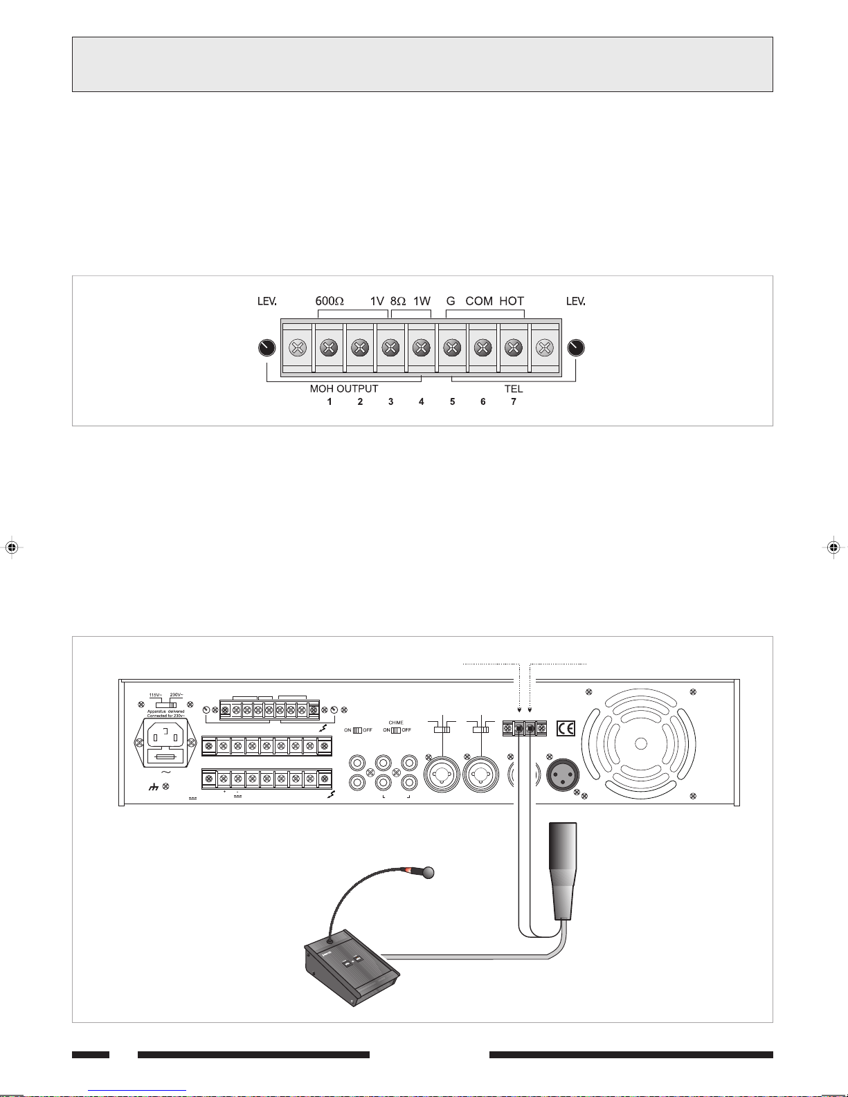
CONNEXIONS
3
ANSCHLÜSSE
3.6 SORTIE MUSIC ON HOLD (MOH)
Les borniers [13] fournissent le signal de la seule source sonore
sélectionnée sur l'entrée INPUT 5 [7]; ce signal n'est pas soumis à la
fonction de priorité micro ou téléphonique.
La sortie équilibrée à transformateur (bornes 1-2-3, fig. 3.6.1) peut être
utilisée pour le contrôle d'un amplificateur supplémentaire, d'un standard
téléphonique ou autre dispositif; la sortie de puissance (bornes 3-4,
fig. 3.6.1) est en mesure de contrôler directement un petit haut-parleur
moniteur de 8 Ω de puissance maximum de 1W.
Il est possible de régler le niveau de sortie par l'intermédiaire du contrôle
LEV. [12].
1: 600Ω (ligne - côté chaud)
(Leitung - warme Seite)
2: 600Ω (ligne - côté froid)
(Leitung - kalte Seite)
3: masse et blindage
Erdung und Abschirmung
4: 1W/8Ω sortie haut-parleurs
Lautsprecherausgang
Fig./Abb. 3.6.1
3.7 PRIORITE MICRO ET SIGNAL D'ANNONCE
En fermant les contacts du bornier PRIORITY [19] la source musicale
sélectionnée et l'entrée INPUT 4 sont coupées (voir Chap. 3.3); la
fermeture du contact produit un signal d'annonce à deux tonalités
(CARILLON/CHIME) lorsque le sélecteur CHIME [17] se trouve sur la
position ON. Il est possible de modifier le niveau du signal d'annonce
en intervenant sur le trimmer semi-fixe VR301 situé sur le circuit de
priorité (voir Chap. 2.3).
Pour utiliser au mieux la fonction de priorité, il est possible d'utiliser le
micro PASO mod. M906 et les bases B501-M et B601 (bases au
nombre de deux maximum).
La fig. 3.7.1 montre un exemple de branchement d'une base B601.
3.6 AUSGÄNGE MUSIC ON HOLD (MOH)
An diesen Klemmen [13] liegt nur das Signal der auf INPUT 5 [7]
gewählten Tonquelle; dieses Signal unterliegt nicht der
Vorrangeinstellung für Mikrofon und Telefon. Insbesondere kann der
symmetrische Ausgang mit Transformator (Klemmen 1-2-3, Abb. 3.6.1)
für die Steuerung eines weiteren Verstärkers, einer Telefonzentrale
oder anderem verwendet werden; Der Leistungsausgang (Klemmen
3-4 der Abb. 3.6.1) kann direkt einen kleinen 8Ω Monitor-Lautsprecher
mit einer Leistung von max. 1 W steuern. Die Stufe ist mittels der
Kontrolle LEV. [12] auf der Rückseite des Geräts einstellbar.
5: TEL (masse et blindage)
(Erdung und Abschirmung)
6: TEL (entrée - côté froid)
(eingang - kalte Seite)
7: TEL (entrée - côté chaud)
(eingang - warme Seite)
3.7 MIKROFONVORRANG UND VORANKÜNDIGUNGSSIGNAL
Bei Schließen der Kontakte des Klemmenbretts PRIORITY [19] werden
die gewählte Musikquelle und der Eingang INPUT 4 stummgeschaltet
(siehe Abschnitt 3.3); das Schließen des Kontakts generiert ein
zweitöniges Vorankündigungssignal (CHIME), wenn sich der Wählschalter
CHIME [17] in der Position ON befindet.
Es besteht die Möglichkeit, die Stufe des Vorankündigungssignals
einzustellen, indem man den halbfesten Trimmer VR301 auf dem
Schaltkreis Priority bedient (siehe Abschnitt 2.3). Zum Zweck einer
wirksamen Nutzung der Vorrangfunktion können das PASO-Mikrofon Mod.
M906 und die Sprechstellen B501-M und B601 verwendet werden
(bis zu max. zwei Sprechstellen). In Abb. 3.7.1 ist ein Anschlussbeispiel
für eine Sprechstelle B601 dargestellt.
18
FUSE T6,3A
CONSUMPT. 200 W
CONSUM T. 200 W
8
W
600
MOHOUTPUT TEL
COM COMCOM VINZ2 Z3Z1
24V COM 50 V 70 V 100 V
GCOMHOT
1V 1W
W
8
W
B601
BLANC / WEIß
LEV.LEV.
AMPLIFIER
AX5120
LINK
PRE OUT
POWER IN
AUX CD
LINE
INPUT 5 INPUT4 INPUT3 MICRO2 MICRO 1
PHANTOM
PHANTOM
MIC
LINE
MIC
+
PRIORITY
VERT / GRÜN
VERDE / GREENBIANCO / WHITE
S.p.A. -ITALY
P
Fig./Abb. 3.7.1
SERIE 5000

3CONNEXIONS
ANSCHLÜSSE
3.6 SORTIES DE PUISSANCE
Les sorties de puissance pour les haut-parleurs sont disponibles sur le
bornier [25]. Il est possible de réaliser un système de diffusion sonore
en utilisant aussi bien des diffuseurs à basse impédance que des
diffuseurs dotés de transformateurs de ligne.
Dans les deux cas, la charge totale ne doit pas surcharger l'amplificateur:
aussi est-il important de ne pas relier de diffuseurs ni de groupes de
diffuseurs d'impédance inférieure à l'impédance nominale de la prise à
laquelle ils sont reliés. Il est recommandé en outre d'accorder une grande
attention au calcul des impédances dans le cas où devraient être
réalisées des installations de diffusion mixtes (à basse impédance et
tension constante).
Le tableau 3.8.1 indique les valeurs nominales de tension et d'impédance
pour les différentes sorties.
Sortie
8 Ω
50 V
70 V
100 V
3.6.1 Systèmes à basse impédance
Pour les applications prévoyant l'utilisation d'un nombre réduits de
haut-parleurs, la ligne de connexion peut être raccordée entre la borne
commune 0 et la prise 8
Le raccordement des haut-parleurs, de type série, parallèle ou mixte,
doit fournir une impédance égale ou supérieure à 8 Ω.
La figure 3.8.1 montre un exemple de raccordement.
AX5240
43,8 V
10,4 Ω
20,4 Ω
41,7 Ω
Tableau 3.8.1
ΩΩ
Ω de la plaquette de connexions [25].
ΩΩ
AX5120
31 V
20,8 Ω
40,8 Ω
83,3 Ω
AX5060
21,9 V
41,7 Ω
81,6 Ω
167 Ω
3.6 LEISTUNGAUSGÄNGE
Die Leistungsausgänge der Lautsprecher sind auf dem Klemmenbrett [25]
installiert. Es können Beschallungsanlagen sowohl durch Lautsprecher mit
niedriger Impedanz als auch durch Lautsprecher mit Linientransformator
aufgebaut werden.
In beiden Fällen darf die Gesamtlast den Verstärker nicht überbelasten:
verwenden Sie keine Lautsprecher oder Lautsprechergruppen mit einer
niedrigeren Impedanz als der Nennimpedanz der Buchse, an die sie
angeschlossen sind. Außerdem wird empfohlen, der Berechnung der
Impedanz besondere Aufmerksamkeit zu widmen, wenn gemischte
Beschallungsanlagen installiert werden sollen (mit niedriger Impedanz
und Gleichspannung).
Die Tabelle 3.8.1 enthält eine Liste der Spannungs- und Impedanznennwerte
für die verschiedenen Ausgänge.
Ausgang
8 Ω
50 V
70 V
100 V
System mit niedriger Impedanz
3.6.1
Bei Anwendungen, die den Einsatz von nur wenigen Lautsprechern
erfordern, kann die Verbindungsleitung zwischen dem gemeinsamen
Endstück 0 und der Buchse 8
werden [25]. Der Anschluss der Lautsprecher, seriell oder parallel
oder auch gemischt, muss eine Impedanz liefern, die gleich oder höher
ist als 8 Ω. Die Abbildung 3.8.1 zeigt ein Anschlussbeispiel dar.
AX5240
43,8 V
10,4 Ω
20,4 Ω
41,7 Ω
Tabelle 3.8.1
AX5120
31 V
20,8 Ω
40,8 Ω
83,3 Ω
ΩΩ
Ω des Klemmenbretts angeschlossen
ΩΩ
AX5060
21,9 V
41,7 Ω
81,6 Ω
167 Ω
Calcul de l'impédance sur les branchements en série
Dans le cas de diffuseurs reliés les uns aux autres en série, l'impédance
totale correspond à la somme de toutes les impédances:
impédance totale = Z1 + Z2 + Z3 + ....
Calcul de l'impédance sur les branchements en parallèle
Dans le cas de diffuseurs reliés les uns aux autres en parallèle, l'impédance
totale peut être calculée par l'intermédiaire de la formule suivante:
impédance totale =
1
+
Z11 Z2
ΩΩ
Ω
ΩΩ
1
1
+ + ......
Z3
ΩΩ
16
Ω16
ΩΩ
Berechnung der Impedanz bei Reihenschaltungen
Bei der Reihenschaltung von Lautsprechern ist die Gesamtimpedanz die
Summe der einzelnen Impedanzwerte:
Gesamtimpedanz = Z1 + Z2 + Z3 + ....
Berechnung der Impedanz bei Parallelschaltungen
Bei parallelgeschalteten Lautsprechern, wird die Gesamtimpedanz nach
der folgenden Formel berechnet:
Gesamtimpedanz =
1
+
Z11 Z2
1
1
+ + ......
Z3
20W 20W
Fig./Abb. 3.8.1
SERIE 5000
Fig./Abb. 3.8.2
19

3.8.2 Systèmes à tension constante
R
f
Pour les installations nécessitant un grand nombre de diffuseurs et/ou
prévoyant une grande distance entre amplificateurs et haut-parleurs, il
est préférable d'utiliser un système de distribution à tension constante
(appelé aussi système à haute impédance). Sur ce type d'installation,
les diffuseurs, dotés de transformateurs d'impédance, sont tous
raccordés sur la ligne en dérivation (voir exemple de la Figure 3.8.2).
Ceci permet de faciliter la réalisation de l'installation, en outre si un
haut-parleur devait, pour une quelconque raison, se débrancher, cela
n'empêche pas le reste de l'installation de fonctionner normalement.
Les tensions constantes disponibles en sortie d'amplificateur sont de
50, 70 et 100 V.
Calcul du nombre de diffuseurs (par les puissances)
Supposons davoir défini aussi bien lamplificateur (cest-à-dire sa
puissance de sortie) que le type de diffuseur, avec la puissance
correspondante absorbée. Dans ce cas, le nombre maximum de
diffuseurs connectables sur la ligne est déterminé par la formule suivante:
Nombre diffuseurs =
Exemple: Emploi d'un amplificateur AX5240 avec un plafonnier modèle
Paso C42. L'amplificateur est en mesure d'émettre une puissance
équivalente à 240 W alors qu'un diffuseur absorbe une puissance de
6 W. Pour savoir combien de diffuseurs peuvent être reliés à la ligne de
sortie on fait l'opération suivante:
Nombre diffuseurs = = 40
Calcul du nombre de diffuseurs (par les impedances)
Si la donnée disponible est limpedance du diffuseur, le nombre maximum
de diffuseurs pouvant être relés à la ligne de sortie on fait lopération
suivante:
Nombre diffuseurs =
Puissance amplificateur
Puissance diffuseur
240 W
6 W
Impédance diffuseur
Impédance amplificateur
3CONNEXIONS
3.8.2
Systeme mit konstanter Spannung
Bei Anlagen mit einer großen Zahl von Lautsprechern bzw. großen
Abständen zwischen Verstärkern und Lautsprechern, ist eine
Gleichspannungsversorgung vozuziehen (definiert auch als hohe
Impedanz). Bei dieser Art von Anlagen, sind die mit
Anpassungstransformatoren ausgerüsteten Lautsprecher mit
Abzweigleitungen angeschlossen (s. Beispiel in Abbildung 3.8.2); Dieses
Detail vereinfacht den Aufbau der Anlage und gewährleistet bei
eventueller Unterbrechung des Lautsprecheranschlusses den ordnungsgemäßen Betrieb der Gesamtanlage. Die am Lautsprecherausgang
zulässigen Gleichspannungen sind entweder 50, 70 oder 100 V.
Berechnung der lautsprecheranzahl (durch die leistungen)
Es wird vorausgesetzt, daß sowohl der Verstärker (d.h. seine
Ausgangsleistung) als auch der Lautsprechertyp mit entsprechender
Leistungsaufnahme definiert ist. In diesem Fall wird die höchste Anzahl
der auf der Leitung anschließbaren Lautsprecher durch die folgende
Formel festgelegt:
Anzahl Lautsprecher =
Beispiel: Es wird ein Verstärker AX5240, Modell Paso C42, verwendet.
Der Verstärker kann eine Leistung von 240 W abgeben, wohingegen
der Lautsprecher eine Leistung von 6 W aufnimmt. Um zu wissen, wie
viele Lautsprecher an die Ausgangsleitung angeschlossen werden
können, wird gerechnet:
Anzahl Lautsprecher = = 40
Berechnung der lautsprecheranzahl (durch die impedanzen)
Wenn die Impedanz des Lautsprechers die zur Verfügungstehende Größe
ist, ist die maximale Anzahl von Lautsprechern, die an eine Leitung
angeschlossen werden können, die folgende:
Anzahl Lautsprecher =
ANSCHLÜSSE
Leistung Verstärker
Leistung Lautsprecher
240 W
6 W
Lautsprecherimpedanz
Impedanz Verstärker
où l'impédance nominale de l'amplificateur peut être obtenue avec le
tableau 3.8.1.
Exemple: Emploi d'un amplificateur AX5240 avec des diffuseurs de
type Paso C55 présentant une impédance de 500 ohm.
Le tableau 3.6.1 nous indique que l'impédance normale de charge de la
ligne à 100 V est de 41,7 ohm.
Par conséquent:
Nombre diffuseurs =
N.B.: dans le cas où les diffuseurs seraient de types différents et/ou
branchés à différentes puissances (le cas le plus fréquent), il est important
de bien s'assurer que la puissance totale requise pour les diffuseurs (qu'il
est possible d'obtenir en faisant simplement la somme de toutes les
puissances) est inférieure à la puissance nominale de l'amplificateur.
3.9 SORTIE ENREGISTREUR/BOOSTER ET PRISE EGALISEUR
Dans le cas où il serait nécessaire de soumettre le signal à un traitement
acoustique, il est possible de brancher un égaliseur ou un élaborateur de
signal, aux prises POWER IN et PRE OUT [16] de l'appareil. Pour
l'activation de l'égaliseur, l'interrupteur LINK présent sur la partie
postérieure de l'appareil doit se trouver sur la position OFF.
Cette configuration permet la correction acoustique dans les espaces
produisant de fortes réverbérations et la suppression des phénomènes
de rétroaction acoustique diffuseur-micro (ou effet Larsen).
Dans le cas où aucun autre appareil externe ne serait relié à l'amplificateur
par l'intermédiaire des prises POWER IN et PRE OUT, l'interrupteur
LINK doit être placé sur la position ON pour garantir la continuité de la
chaîne d'amplification. La prise de sortie PRE OUT fournit le signal de
commande de la section de puissance constitué du mixage des différentes
sources en aval du contrôle de volume général MASTER VOLUME [5].
Ce signal peut être utilisé pour la commande d'une unité de puissance et/
ou dévié vers un appareil d'enregistrement.
500 Ω
41,7 Ω
= 12
Die Nennimpedanz des Verstärkers kann aus der Tabelle 3.8.1
entnommen werden.
Beispiel: Es wird ein Verstärker AX5240 mit Lautsprechern Paso C55
verwendet, die eine Impedanz von 500 ohm aufweisen.
Aus der Tabelle 3.6.1 ist ersichtlich, daß die Nennlastimpedanz der
Leitung bei 100 V gleich 41,7 ohm ist.
Daraus folgt:
Anzahl Lautsprecher =
N.B.: in dem häufiger vorkommenden Fall, dass die Lautsprecher
unterschiedlichen Typs sind und/oder unterschiedliche Leistungen
besitzen, ist es wichtig, immer die von den Lautsprechern geforderte
Gesamtleistung zu überprüfen (durch Summierung der einzelnen
Leistungen), die niedriger als die Nennleistung des Verstärkers sein
muss.
3.9 AUSGANG AUFNAHMEGERÄT/BOOSTER UND BUCHSE EQUALIZE
In den Fällen, in denen eine Tonbearbeitung des Signals erfolgen soll,
kann ein Equalizer oder ein anderes Gerät für die Tonbearbeitung an die
Buchsen POWER IN und PRE OUT [16] des Geräts angeschlossen
werden. Für den Anschluss des Equalizers muss der Schalter LINK au
der Rückseite des Geräts in die Position OFF gesetzt werden.
Durch diese Operation ist die akustische Korrektur in besonders hallenden
Räumen und die Unterdrückung der akustischen Rückkopplung zwischen
Lautsprecher und Mikrofon (Larsen-Effekt) möglich.
Wenn über die Buchsen POWER IN und PRE OUT keine externen Geräte
angeschlossen sind, muss der Schalter LINK in die Position ON gestellt
werden, um die Kontinuität der Verstärkerkette zu gewährleisten.
An der Ausgangsbuchse PRE OUT ist das leistungsseitige Steuersignal
verfügbar, das aus der Mischung der verschiedenen Quellen vor der
generellen Lautstärkekontrolle MASTER VOLUME [5] besteht. Dieses
Signal kann für die Steuerung der Leistungseinheiten verwendet werden
und/oder an ein Aufnahmegerät geleitet werden.
500 Ω
41,7 Ω
= 12
20
SERIE 5000

3CONNEXIONS
O
O
ANSCHLÜSSE
3.10 SELECTION DE ZONES D'ECOUTE
Les amplificateurs de la Série 5000 offrent la possibilité d'activer/
désactiver de manière indépendante un maximum de trois zones de
diffusion par l'intermédiaire des interrupteurs ZONE 1, ZONE 2 et
ZONE 3 [1]. Dans ce cas, les trois zones de diffusion doivent être
reliées au bornier [24],
en tenant compte dans tous les cas de la
charge nominale maximum admise par l'appareil (voir Chap. 3.8.2).
Il est en outre possible de sélectionner simultanément toutes les zones
d'écoute par l'intermédiaire de l'interrupteur ALL. Les sélections
effectuées par l'intermédiaire des interrupteurs [1] sont confirmées par
l'allumage des témoins lumineux correspondants. Les interrupteurs
coupent le raccordement des lignes à tension constante sur les
terminaisons du bornier [24].
La sélection de la tension de ligne pour les différentes zones doit
s'effectuer en branchant, par l'intermédiaire d'une longueur de fil, la
terminaison V IN du bornier [24] à la terminaison correspondant à la
tension voulue sur le bornier [25]. La fig. 3.10.1 montre un exemple de
branchement à trois zones de diffusion sur tension de ligne de 100V.
8
W
Z2
GCOMHOT
Z3
600
1V 1W
W
MOH OUTPUT TEL
COM COMCOM
Z1
FUSE T6,3A
CONSUMPT. 200 W
3.10 AUSWAHL DER KLANGZONE
Die Verstärker der Serie 5000 verfügen über die Möglichkeit, unabhängig
mit Hilfe der Schalter ZONE 1, ZONE 2 e ZONE 3 [1] bis zu drei
Klangzonen zu ein- bzw. auszuschalten. In diesem Fall müssen die drei
Lautsprecherzonen an das Klemmenbrett [24] angeschlossen werden,
wobei die maximale für das Gerät zulässige Nennleistung berücksichtigt
werden muss (siehe Abschnitt 3.8.2).
Außerdem können sämtliche Klangzonen gleichzeitig mit dem Schalter
ALL aktiviert werden. Die Auswahloperationen mit Hilfe der Schalter [1]
werden durch das Aufleuchten der entsprechenden LED bestätigt.
Die Schalter unterbrechen den Anschluss der Gleichspannungsleitungen
an den Endstücken des Klemmenbretts [24].
Die Wahl der Leitungsspannung für die einzelnen Zonen muss mit Hilfe
eines Kabelstücks des Endstücks V IN des Klemmenbretts [24] an das
Endstück angeschlossen werden, das der am Klemmenbrett [25]
gewünschten Spannung entspricht. In Abb. 3.10.1 ist das Beispiel des
Anschlusses an drei Klangzonen mit einer Leitungsspannung von 100V
dargestellt.
LEV.LEV.
LINK
PRE OUT
VIN
AMPLIFIER
AUX CD
AX5120
PHANTOM
MIC
LINE
PHANTOM
LINE
MIC
+
PRI
CONSUM T. 200 W
24 V COM 50 V 70 V 100 V
8
W
ZONE 2
ZONE 1
Fig./Abb. 3.10.1
ZONE 3
POWER IN
INPUT 5 INPUT 4 INPUT 3 MICR
SERIE 5000
21

GEBRAÜCH DES GERATES4UTILISATION DE LAPPAREIL
4.1 MISE EN MARCHE
Avant d'allumer l'appareil, s'assurer que tous les branchements
nécessaires à l'installation ont bien été effectués de même que les
configurations de fonctionnement.
Placer l'interrupteur d'alimentation [4] en position ON.
Le voyant lumineux POWER [3] confirmera la mise en marche de
l'appareil. Si nécessaire, régler le volume d'écoute par l'intermédiaire du
contrôle MASTER VOLUME [5] et ajuster le niveau des sources audio
pour obtenir la bonne égalisation des signaux par l'intermédiaire des
contrôles de volume [8], [9], [10] et [15].
4.2 CONTROLE DE VOLUME PRINCIPAL
Le contrôle de volume principal MASTER VOLUME [5] règle le volume
général du signal de sortie, dérivant du mixage des différents signaux
d'entrée. Pour obtenir en sortie un signal sans distorsion, il est conseillé
de contrôler que le voyant rouge (+1dB) de l'indicateur du niveau de
sortie [2] ne s'allume pas ou, tout au plus, que cela n'ait lieu que de
temps à autre; autrement, il faudra diminuer le niveau de sortie en
actionnant la commande MASTER VOLUME [5].
La puissance de sortie nominale est signalée par l'allumage du voyant
lumineux jaune (0 dB).
4.3 CORRECTION ACOUSTIQUE
Les contrôles BASS et TREBLE [6] permettent de modifier la tonalité du
signal de sortie dérivant du mixage des différents signaux d'entrée.
Contrôle tonalité basses (BASS)
La commande BASS règle les prestations de l'amplificateur pour les basses
fréquences. La position médiane 0 fournit une réponse de type linéaire;
pour avoir une exaltation des fréquences basses, tourner le bouton en
sens HORAIRE. En utilisant des diffuseurs à pavillon il est conséillé
d'atténuer les fréquences basses à l'aide de la commande BASS; un niveau
excessif des basses fréquences pourrait endommager la membrane du
diffuseur.
Contrôle tonalité aigues (TREBLE)
Le contrôle TREBLE règle les prestations acoustiques de l'amplificateur
pour les hautes fréquences. La position médiane 0 fournit une réponse
de type linéaire; pour avoir une exaltation des fréquences hautes,
tourner le bouton en sens HORAIRE. L'atténuation des tonalités aiguës
permet de réduire un niveau de bruit excessif et d'adoucir les sons
particulièrement chuintant.
4.1 EINSCHALTEN
Vor Einschalten des Geräts muss sichergestellt werden, dass alle für die
komplette Installation der Anlage erforderlichen Anschlüsse hergestellt
und die Betriebseinstellungen vorgenommen wurden.
Den Netzschalter [4] auf ON schalten.
Die POWER Leuchtanzeige [3] bestätigt das Einschalten des Gerätes.
Falls erforderlich, die Lautstärkestufe mit Hilfe der Kontrolle MASTER
VOLUME [5] einstellen und die Feineinstellung der Stufen der Tonquellen
zum Zweck eines richtigen Ausgleichs der Signale vornehmen [8], [9],
[10] und [15].
4.2 STEUERUNG DER HAUPTLAUTSTÄRKE
Die Hauptkontrolle der Lautstärke MASTER VOLUME [5] reguliert die
Gesamtstufe des Ausgangssignals, das aus der Mischung der
verschiedenen Eingangssignale stammt. Um ein Ausgabesignal ohne
Verzerrung zu erhalten, wird empfohlen, zu überprüfen, ob sich auf dem
Ausgangspegelanzeiger [2] nicht die rote Kontrollampe einschaltet
(+1 dB) oder ob dies in unregelmäßigen Abständen geschieht; wenn
nicht, ist es notwendig, den Ausgabepegel durch Betätigung der Steuerung
MASTER VOLUME [5] herabzusetzen. Die Ausgangsnennleistung wird
durch das Einschalten der gelben Kontrollampe (0 dB) angezeigt.
4.3 TONKORREKTUR
Die Kontrollen BASS und TREBLE [6] ändern den Ton des Ausgangssignals,
das aus der Mischung der verschiedenen Eingangssignale stammt
Tiefenkontrolle (BASS)
Die BASS-Steuerung reguliert die Tonleistung des Verstärkers bei niedriger
Frequenz. Die zentrale Position 0 gibt eine lineare Antwort; für
eineVerstärkung der Niederfrequenzen den Drehknopf im
UHRZEIGERSINN drehen. Bei Benutzung trichterförmiger Lautsprecher
ist es angebracht, die niedrigen Frequenzen mit der BASS-Steuerung zu
dämpfen; übertrieben niedrige Frequenzen könnten die Membran des
Lautsprechers beschädigen.
Kontrolle hohe töne (TREBLE)
Die TREBLE-Steuerung reguliert die Tonabgabe des Verstärkers bei hoher
Frequenz. Die zentrale Position 0 gibt eine lineare Antwort; für eine
Verstärkung der hohen Frequenzen den Drehknopf im Uhrzeigersinn
drehen; für eine Dämpfung der hohen Frequenzen den Knopf gegen den
UHRZEIGERSINN drehen. Die Abschwächung von Hochtönen ist für die
Minimierung eines zu hohen Nebengeräuschpegels hilfreich sowie auch
für die Abschwächung von zu stark pfeifenden Tönen.
4.4 SURCHARGE ET PROTECTION
Appliquer une valeur d'impédance de charge inférieure à la valeur nominale
a pour effet de demander à l'appareil une puissance supérieure à celle
disponible en continuité. Dans ce cas, les paliers terminaux de puissance
sont susceptibles d'être endommagés, de même que les transformateurs
d'alimentation et de sortie.
Pour prévenir ce type de problème, les amplificateurs de la Série 5000
sont dotés de nombreux circuits et dispositifs de protection contre les
surcharges et les courts-circuits:
- circuit de limitation des pics de courant de sortie: son intervention est
instantanée en cas de surcharge.
- interrupteur thermique à réarmement automatique: installé au contact
du dissipateur des transistors de puissance, il coupe l'alimentation des
circuits de commande et annule par conséquent le signal de sortie
dans le cas où la température des paliers terminaux attendrait des
valeurs dangereuses. Le réarmement est automatique dès que la
température est à nouveau en deçà de la limite de fonctionnement.
- fusible de secteur (accessible sur la prise de secteur [28]) et fusible
d'alimentation interne à basse tension (accessible à l'intérieur de
l'appareil sur le circuit d'alimentation): ces deux fusibles assurent
l'interruption immédiate du fonctionnement de l'appareil en cas
d'anomalie interne.
Enfin, il convient de signaler que les modèles AX5120 et AX5240 sont
dotés de ventilateur de refroidissement, à vitesse contrôlée
automatiquement en fonction de la température du dissipateur sur lequel
sont appliqués les dispositifs de puissance.
22
4.4 ÜBERLASTUNG UND SCHUTZ
Die Verwendung eines niedrigeren Verbraucherimpedanzwertes als dem
des Nennwertes entsprechenden Wertes bedeutet, vom Gerät eine
höhere Leistung als die kontinuierlich lieferbare Leistung zu verlangen.
Dies kann zur Beschädigung der Endleistungsstadien sowie der
Speisungstransformatoren und Ausgangstransformatoren führen.
Um dies zu vermeiden, besitzen die Verstärker der Serie 5000 eine
große Zahl an Sicherungsschaltkreisen und -vorrichtungen gegen
Überlastungen und Kurzschlüsse:
- Schaltkreis für die Stromspitzenbegrenzung am Ausgang: sein
Einsetzen erfolgt unmittelbar, er setzt bei Überlastung ein.
- Rückstellbarer Wärmeschalter: liegt am Kontakt des Verteilers der
Leistungstransistoren, unterbricht die Versorgung der Steuerschaltkreise
und annulliert dementsprechend das Ausgangssignal, wenn die
Temperatur der Endstufen gefährliche Werte erreicht. Die
Wiederaufnahme erfolgt automatisch sobald die Temperatur in den
Bereich des normalen Betriebs zurückkehrt.
- Netzsicherungen (Zugang an der Netzbuchse [28]) und Sicherungen
der internen Niederspannungsspeisung (Zugang über den Innenraum
des Geräts, sie liegen auf dem Versorgungsschaltkreis): diese
Vorrichtungen gewährleisten die unmittelbare Blockierung des Betriebs
des Verstärkers, wenn in dessen Innern ein Schaden vorhanden ist.
Außerdem wird darauf hingewiesen, dass die Modelle AX5120 und
AX5240 einen Kühlventilator mit automatischer Geschwindigkeitskontrolle
auf der Basis der Temperatur des Wärmeableiters besitzt, auf dem die
Leistungsvorrichtungen montiert sind.
SERIE 5000

TECHNISCHE EIGENSCHAFTEN5CARACTÉRISTIQUES TECHNIQUES
0605XA 0215XA 0425XA
)acV032@(eitrosedelanimonecnassiuP W06 W021 W042 )acV032@(gnutsielsgnagsuAelanimoN
)ccV42@(eitrosedelanimonecnassiuP W35 W79 W651 )ccV42@(gnutsielsgnagsuAelanimoN
etnatsnocnoisnetàseitroS V05,07,001 gnunnapshcielGiebegnägsuA
ecnadepmiessabàseitroS 8 Ω znadepmIregirdeiniebegnägsuA
elanimonecnassiupalànoisrotsiD %5,0< gnutsiellanimoNiebgnurrezreV
rutkerroknoT-étilanotednoitcerroC
sevarG )zH001@(Bd11± enötfeiT
sugiA )zHk01@(Bd11± enöthcoH
egnägnienoforkiM-seuqinohporcimseértnE
ecnadépmi/étilibisneS 0001/Vm1,1 Ω znadepmI/tiekhcildnifpmE
tiurb/langistroppaR Bd26 gnurötS/langiSnovsintlähreV
ecneuqérfneesnopéR )Bd3/0(zH000.91÷54 gnagzneuqerF
motnahPnoitatnemilA V5.61 gnutielsmotnahP
egnägniesgnutieL-engiledseértnE
ecnadépmi/étilibisneS 0001/Vm021 Ω znadepmI/tiekhcildnifpmE
tiurb/langistroppaR Bd28 gnurötS/langiSnovsintlähreV
ecneuqérfneesnopéR )Bd3/0(zH000.12÷04 gnagzneuqerF
egnägniesfliH-seriailixuaseértnE
DCeértneecnadépmi/étilibisneS /Vm005k72Ω gnagniE-DCznadepmI/tiekhcildnifpmE
XUAeértneecnadépmi/étilibisneS k51/Vm022 Ω gnagniE-XUAznadepmI/tiekhcildnifpmE
tiurb/langistroppaR Bd28 gnurötS/langiSnovsintlähreV
ecneuqérfneesnopéR )Bd3/0(zH000.22÷03 gnagzneuqerF
étiroirpnoitaunéttA Bd05 gnufpmädgnarroV
gnagnienofeleT-euqinohpeleteértnE
ecnadépmi/étilibisneS /Vm021k7.5Ω znadepmI/tiekhcildnifpmE
tiurb/langistroppaR Bd38 gnurötS/langiSnovsintlähreV
ecneuqérfneesnopéR )Bd3/0(zH000.01÷002 gnagzneuqerF
egnägsualangiS-langisedseitroS
HOMengiL 006/V4,1Ω HOMgnutieL
HOMruetinomecnassiuP 8/W1Ω HOMrotinoMgnutsieL
TUOERPeitroS 006/V1Ω gnagsuA-TUOERP
SERIE 5000
23

ERSATZTEILLISTE6LISTE DES PIÈCES DÉTACHÉES
NOITPIRCSED 0605XA 0215XA 0425XA GNUBIERHCSEB
elcrevuoC 3/6399 lekceD
éihpargiréslatnorfuaennaP 1/6399 leenaptnorFsetkcurdebbeiS
uaeséredruetpurretnI 1/9199 retlahcszteN
noitatnemila'druetamrofsnarT 2FT99 3FT99 1FT99 rotamrofsnartsgnusiepS
eitrosedruetamrofsnarT 3UT99 2UT99 1UT99 rotamrofsnartsgnagsuA
etolipruetamrofsnarT - - 1IT99 rotamrofsnartreuetS
notuoB D-85/82 fponK
ruetapissid+ecnassiupedtiucricepuorG 3/7299 2/7299 1/7299 retielbaemräW+sierktlahcssgnutsieLtiehniE
ruetacifilpmaérptiucricepuorG - - 6/7299 rekrätsrevroVsierktlahcStiehniE
reteM-uVtiucricepuorG 8/7299 7/7299 reteM-uVgnutlahcStiehniE
enohpélét/HOMtiucricepuorG 01/7299 9/7299 nofeleT/HOMsierktlahcStiehniE
ruetatnemilatiucricepuorG 41/7299 31/7299 21/7299 sierktlahcssgnugrosreVtiehniE
GNOD-GNIDtiucricepuorG 71/7299 61/7299 GNOGgnutlahcStiehniE
DC/XUAruetceléstiucricepuorG 51/7299 DC/XUAretlahcslhäWsierktlahcStiehniE
seitrossreinrobepuorG 91/7299 egnägsuAretterbnemmelKtiehniE
senozeitrossreinrobepuorG 02/7299 nenoZgnagsuAretterbnemmelKtiehniE
stnayovcevasenozruetcelésepuorG 12/7299 DELtimretlahcslhäwnenoZtiehniE
tnemissidiorferedruetalitneV - 1TV99 rotalitnevlhüK
8724CrotsisnarT 1/7199 8724CrotsisnarT
966DrotsisnarT 2/7199 966DrotsisnarT
C599MérgétnitiucriC 1/8199 C599MgnutlahcSetreirgetnI
8602érgétnitiucriC 2/8199 8602gnutlahcSetreirgetnI
4822AKérgétnitiucriC 3/8199 4822AKgnutlahcSetreirgetnI
)sétilanot(BK05ertèmoitnetoP 1/2199 )nenoT(retemoitnetoPBK05
)xuaevin(AK05ertèmoitnetoP 2/2199 )efutS(retemoitnetoPAK05
24
SERIE 5000

DESCRIPCIÓN GENERAL1ALGEMENE BESCHRIJVING
12
SERIES
AX5000
1.1 FRONTPANEEL
Keuzetoetsen zones.
[1]
[2] Display uitgangsniveau.
[3] Startcontrolelamp.
[4] Netschakelaar.
[5] Algemene volumeregelaar.
[6] Toonregelaars.
[7] Keuzeschakelaar hulpingangen.
[8] Niveauregeling hulpingang.
[9] Niveauregelingen ingangen 3 en 4.
[10] Niveauregeling microfooningangen.
11 12 15 16 17 18 1913 14
INTEGRATED AMPLIFIER
INPUT 3 INPUT 4MICRO 1 MICRO 2
INPUT 5
ZONE 1 ZONE 3ZONE 2 ALL
AUX CD
0
101010101010 00000
BASS
0
10
+10
TREBLE
+10
MASTER VOLUME
1.1 PANEL FRONTAL
Selectores de las zonas.
[1]
[2] Visualizador del nivel de salida.
[3] Chivato de encendido.
[4] Interruptor de red.
[5] Mando de volumen general.
[6] Mandos de tono.
[7] Selector entradas auxiliares.
[8] Mando nivel entrada auxiliar.
[9] Mandos de nivel entradas 3 y 4.
Controles de nivel de las entradas microfónicas.
[10]
OUTPUT LEVEL
POWER
0
10
456910 8 7 3
8
W
1V 1W
8
W
GCOMHOT
LINK
PRE OUT
POWER IN
FUSE T6,3A
CONSUMPT. 200W
CONSUM T. 200 W
600
W
MOHOUTPUT TEL
COM COMCOM V INZ2 Z3Z1
24V COM 50V 70V 100V
1.2 ACHTERPANEEL
Keuzeschakelaar netspanning.
[11]
[12] Niveauregeling uitgang MUSIC ON HOLD.
[13] Lijn- en vermogensuitgangen (1W/8Ω) MUSIC ON HOLD.
[14] Gebalanceerde telefooningang.
[15] Niveauregeling telefooningang.
[16] Stopcontact voor externe equalizer.
[17] Chime ON/OFF.
[18] Keuzeschakelaars bedrijfsmodi ingangen 3 en 4.
Klemmenstrook voor voorrangscontact.
[19]
[20] Luchtinlaat koelventilator.
[21] Microfooningangen.
[22] MIC/LINE ingangen.
[23] Hulpingangen.
Klemmenstrook voor geselecteerde zones.
[24]
[25] Klemmenstrook luidsprekeruitgangen.
[26] Klemmenstrook voor ext. gelijkstroomvoeding.
[27] Frameaansluiting.
[28] Netstekker met ingebouwde zekering.
+
PRIORITY
S.p.A. - ITALY
P
AMPLIFIER AX5120
LINE
AUX CD
INPUT 5 INPUT 4 INPUT 3 MICRO 2 MICRO 1
PHANTOM
PHANTOM
MIC
MIC
LINE
1.2 PANEL TRASERO
Selector de la tensión de red.
[11]
[12] Regulación nivel salida MUSIC ON HOLD.
[13] Salidas de línea y de potencia (1W/8Ω) MUSIC ON HOLD.
[14] Entrada telefónica balanceada.
[15] Regulación nivel entrada telefónica.
[16] Toma para ecualizador externo.
[17] Chime ON/OFF.
[18] Selectores modalidad funcionamiento entradas 3 y 4.
Terminal de conexión para contacto precedencia.
[19]
[20] Toma de ventilación rotor de enfriamiento.
[21] Entradas microfónicas.
[22] Entradas MIC/LINE.
Entradas auxiliares.
[23]
[24] Terminal de conexión para zonas seleccionadas.
[25] Terminal de conexión salidas altavoces.
[26] Terminal de conexión para alimentación externa en c.c.
[27] Conexión bastidor.
[28] Clavija de red con fusible incorporado.
202122232425262728
SERIE 5000
25

ADVERTENCIAS GENERALES2ALGEMENE AANWIJZINGEN
2.1 INSTALLATIE
Al het apparatuur van PASO is vervaardigd met inachtneming van de
internationale wettelijke veiligheidsvoorschriften en overeenkomstig de
vereisten van de Europese Gemeenschap. Voor een correct en doelmatig
gebruik van het apparaat is het van belang kennis te nemen van alle
kenmerken ervan en de bijgaande aanwijzingen aandachtig te lezen,
waarbij bijzondere aandacht aan de veiligheidsregels dient te worden
besteed. Wanneer het apparaat aan staat, dient voor een adequate
ventilatie te worden gezorgd. Plaats het apparaat niet in een kast
zonder ventilatie en sluit de ventilatiesleuven en in het bijzonder de
achterste luchtinlaat van de koelventilator niet af.
Stel het apparaat bovendien niet op in de buurt van warmtebronnen.
Dit apparaat is geschikt voor montage in standaard rack meubel van
19 met behulp van het optionele accessoire AC55.
Er wordt aanbevolen een ventilatiepaneel tussen de apparaten te
plaatsen (zie afb. 2.1.1).
2.1 INSTALACIÓN
Todos los aparatos PASO están fabricados conforme a las más severas
normas internacionales de seguridad y según los requisitos de la
Comunidad Europea. Para una utilización correcta y eficaz del aparato
es importante tener conocimiento de todas las características, leyendo
detenidamente estas instrucciones y en particular las notas de
seguridad. Durante el funcionamiento del aparato es necesario asegurar
una adecuada ventilación. Evítese encerrar el aparato en un mueble sin
ventilación o tapar las ranuras de ventilación, y en particular la toma de
aire trasera del rotor de enfriamiento.
Evítese así mismo poner el aparato cerca de fuentes de calor.
Este aparato está predispuesto para el montaje en mueble rack standard
de 19 utilizando el accesorio en opción AC55.
Se aconseja intercalar un panel de ventilación entre un aparato y el
otro (ver fig. 2.1.1).
Afb./Fig. 2.1.1
2.2 VOEDING
Dit apparaat is geschikt om te functioneren op een netspanning van
230 V ± 10% 50/60 Hz. Het kan bovendien ook worden gebruikt met
een netspanning van 115 V ± 10% 50/60 Hz; hiervoor dient de
schakelaar [11] op stand 115 V te worden gebracht.
De versterkers van de Serie 5000 kunnen ook gevoed worden met een
externe gelijkstroombron met een spanning van 24V die, volgens de
juiste polariteit, moet worden verbonden met de betreffende klemmen
van de klemmenstrook [26]. De startschakelaar [4] werkt, volgens de
veiligheidsvoorschriften, alleen op de netspanning.
Bij het apparaat wordt een voedingskabel met een aarddraad geleverd;
de overeenkomstige klem op de netstekker mag in geen enkel geval
worden verwijderd.
Sluit de netstekker [28] van het apparaat aan op het lichtnet, waarbij
u de speciale bijgeleverde kabel gebruikt; ga na of het stopcontact
overeenkomstig de wettelijke voorschriften geaard is.
Het apparaat is beveiligd met twee zekeringen (zie par. 4.4).
2.3 OPMERKINGEN OVER DE VEILIGHEID
Ingrepen aan de binnenkant van het apparaat, zoals de selectie van
bepaalde gebruiksmodes, het aanbrengen van hulpstukken of het
vervangen van zekeringen, mag uitsluitend door gespecialiseerd
personeel verricht worden: Indien u de deksel verwijdert krijgt u
toegang tot de delen die gevaar op elektrische schokken kunnen
opleveren. Controleer altijd of de netstekker is losgekoppeld alvorens
het deksel te verwijderen. Indien er per ongeluk vloeistof op het
apparaat valt, dient u onmiddellijk de stekker uit de contactdoos te
verwijderen en het dichtstbijzijnde PASO servicecentrum te hulp te
roepen. De frame-massaverbinding [27] maakt mogelijk dat andere
apparatuur verbonden wordt met als enige functie dat signalen met
een laagniveau worden afgeschermd:
gebruikt worden voor de veiligheidsverbindingen tussen frame en
aarding.
26
dit stroomafnamepunt mag niet
SERIE 5000
2.2 ALIMENTACIÓN
Este aparato está predispuesto para el funcionamiento con tensión de red
a 230 V ± 10% 50/60 Hz. Es posible utilizar el aparato también con una
tensión de red de 115 V ± 10% 50/60 Hz; con tal fin es necesario poner
el selector [11] en la posición 115 V.
Los amplificadores de la Serie 5000 también se pueden alimentar con
una fuente externa de corriente continua con tensión de 24V, que se
debe aplicar, respetando las polaridades, en los correspondientes
terminales de la bornera [26].
Conforme a las normas de seguridad, el interruptor de encendido [4]
actúa sólo sobre la tensión de red. Junto con el aparato es suministrado
un cable de alimentación con hilo de tierra; el terminal de tierra de la
clavija de red no se debe quitar nunca.
Conectar la clavija de red [28] del aparato a la red eléctrica utilizando
el cable previsto incluido en el suministro; comprobar que la toma de
corriente disponga de conexión de tierra conforme a las normas de ley.
El aparato está protegido por dos fusibles (ver párr. 4.4).
2.3 NOTAS SOBRE LA SEGURIDAD
Toda intervención dentro del aparato, como cuando se debe seleccionar
algunos modos de uso o cambiar fusibles, debe ser efectuada por
personal especializado: quitando la tapa se deja al descubierto las
partes a riesgo con el peligro de sacudidas eléctricas.
Antes de quitar la tapa cerciorarse siempre que el cable de conexión
con la red esté desenchufado.
Si accidentamente se vierten líquidos en el aparato, desenchufar
inmediatamente el aparato y contactar el centro de asistencia posventa
PASO más cercano.
La conexión de masa de bastidor [27] permite conectar otros equipos
solamente para la función de protección de las señales de bajo nivel:
esta toma no debe ser utilizada para la conexión de seguridad del
bastidor a tierra.
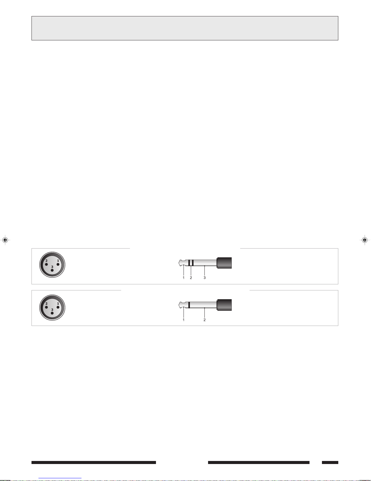
CONEXIONES3AANSLUITINGEN
3.1 ALGEMENE CRITERIA
Voor een goede werking van het apparaat verdient het aanbeveling
enkele algemene criteria in acht te nemen bij het uitvoeren van de
aansluiting van de versterkerinstallatie:
plaats kabels en microfoons niet op het meubel van het apparaat;
leg de signaallijnen niet parallel aan die van het elektriciteitsnet; houd
een afstand van tenminste 30/40 cm aan;
plaats de ingangs- en uitgangslijnen (luidsprekers) op een afstand van
elkaar.
plaats de microfoons buiten de straalhoek van de luidsprekers ter
voorkoming van het akoestischerondzing verschijnsel (Larseneffect).
3.2 MICROFOONINGANGEN
Op de aansluitingen XLR MICRO 1 en MICRO 2 [21] kunnen
PASO telefoons van het dynamische type en elektretmicrofoons met
Phantom voeding worden aangesloten; de aansluitingen zijn
weergegeven op Afb. 3.2.1.
Nog meer aansluitmogelijkheden, waarbij de PRIORITY [19]
klemmenstrook wordt gebruikt, zijn beschreven in par. 3.7.
Iedere microfooningang beschikt over een eigen niveauregelaar [10]
om het vermogen van de verschillende signalen te kunnen regelen.
De microfooningang MICRO 1 beschikt bovendien over de
automatische voorrangsfunctie (VOX): wanneer in de microfoon
gesproken wordt die is verbonden met deze ingang, worden de
hulpingangen en de ingang INPUT 4 (indien geselecteerd, zie par.
3.3) automatisch tijdelijk uitgeschakeld (mute); het niveau van de
activeringsdrempel van het automatische voorrangscircuit is niet
afhankelijk van de positie van de regelaar MICRO 1 [10].
De microfooningangen [21] zijn uitgerust met Phantom voeding voor
elektretmicrofoons van 12/24V.
In het geval u de Phantom voeding af wilt koppelen, doet u dit via de
bruggen SW201 - SW202 op het ingangencircuit (zie par. 2.3).
3.1 CRITERIOS GENERALES
Para un correcto funcionamiento del aparato es necesario observar
algunos criterios de máxima cuando se efectúan las conexiones de la
instalación de amplificación:
- evitar el posizionamiento de cables y de micrófonos sobre el mueble del
aparato;
- evitar extender las líneas de señal paralelas a las de la red eléctrica;
dejar una distancia mínima de 30/40 cm;
- posicionar las líneas de entrada y las líneas de salida (altavoces)
distantes entre ellas;
- posicionar los micrófonos fuera del alcance del ángulo de los difusores
sonoros para evitar el fenómeno de reacción acústica (efecto Larsen).
3.2 ENTRADAS MICROFÓNICAS
En las tomas XLR MICRO 1 y MICRO 2 [21] es posible conectar
micrófonos PASO de tipo dinámico y de electreto con alimentación
phantom; las conexiones con estas tomas se indican en la Fig. 3.2.1.
Ulteriores posibilidades de conexión, que explotan la utilización de
la bornera PRIORITY [19], se indican en el párr. 3.7.
Cada entrada microfónica dispone de su propio mando de nivel [10] para
regular oportunamente la amplitud de las diversas señales.
La entrada microfónica MICRO 1 dispone, además, de la función
de precedencia automática (VOX): hablando por el micrófono
conectado con esta entrada son enmudecidas automáticamente las
entradas auxiliares y la entrada INPUT 4 (si seleccionada, ver
párr. 3.3); el nivel del umbral de activación del circuito de
precedencia automática no depende de la posición del mando
MICRO 1 [10].
Las entradas microfónicas [21] disponen de alimentación Phantom
para micrófono de electreto 12/24V.
Si se desea desconectar la alimentación Phantom, actuar sobre
los puentes SW201 - SW202 situados en el circuito entradas (ver
párr. 2.3).
GEBALANCEERDE TYPE - TIPO BALANCEADO
1 = afscherming / blindaje
2 = signaal (warme kant) / señal (lado caliente)
3 = signaal (koude kant) / señal (lado frío)
NIET-GEBALANCEERDE TYPE - TIPO NO BALANCEADO
1 = afscherming en massa / blindaje y masa
2 = afscherming en massa / blindaje y masa
3 = signaal / señal
Afb./Fig. 3.2.1
3.3 MIC/LINE INGANGEN
De aansluitingen INPUT 3 en INPUT 4 [22] kunnen op onafhankelijke
wijze geconfigureerd worden als microfooningangen (met of zonder
Phantom voeding) of als lijningangen. De selectie van de gebruikswijze
geschiedt met behulp van de schakelaars met drie standen [18]:
in de stand MIC wordt de microfoongevoeligheid geselecteerd, met
gedeactiveerde Phantom voeding;
in de stand PHANTOM wordt de microfoongevoeligheid geselecteerd,
met geactiveerde Phantom voeding (voor 12/24V elektretmicrofoons);
in de stand LINE wordt de lijngevoeligheid geselecteerd.
De aansluiting kan zowel met stekers van het type XLR mannelijk als met
jackstekers van ¼ inch tot stand worden gebracht.
De aansluitingen zijn weergegeven op Afb. 3.2.1.
Iedere microfooningang beschikt over een eigen niveauregelaar [9] om
het vermogen van de verschillende signalen te kunnen regelen.
De ingang INPUT 4 kan wel of niet ondergeschikt worden gemaakt aan
de automatische voorrang (VOX) van de ingang MICRO 1 en aan de
sluiting van het PRIORITY voorrangscontact. In het geval u deze functie
wilt deactiveren, doet u dit met behulp van de brug SW207 op het
ingangencircuit (zie par. 2.3).
1 = signaal (warme kant) / señal (lado caliente)
2 = signaal (koude kant) / señal (lado frío)
3 = afscherming / blindaje
1 = signaal / señal
2 = afscherming en massa / blindaje y masa
3.3 ENTRADAS MIC/LINE
Las tomas INPUT 3 y INPUT 4 [22] son configurables de manera
independiente como entradas microfónicas (con o sin alimentación
phantom) o como entradas de línea. La selección de la modalidad se
consigue mediante los desviadores de tres posiciones [18]:
en posición MIC, se selecciona la sensibilidad microfónica con
alimentación phantom desactivada;
en posición PHANTOM, se selecciona la sensibilidad microfónica
activando la alimentación phantom (para micrófonos de electreto 12/
24V);
en posición LINE, se selecciona la sensibilidad de línea.
Es posible efectuar la conexión tanto con clavijas de tipo XLR macho
como con conectadores jack 1/4.
Las conexiones con estas tomas se indican en la Fig. 3.2.1.
Cada entrada dispone de su propio mando de nivel [9] para regular
oportunamente la amplitud de las diversas señales.
La entrada INPUT 4 puede ser sometida o no a la precedencia
automática (VOX) de la entrada MICRO 1 y al cierre del contacto de
precedencia PRIORITY. Si se desea desactivar esta función, actuar
sobre el puente SW207 situado en el circuito entradas (ver párr. 2.3).
SERIE 5000
27

3AANSLUITINGEN
CONEXIONES
3.4 HULPINGANGEN
Op de phono-aansluitingen AUX en CD [23] kunnen twee
muziekbronnen van hoog niveau (cd-lezer, bandrecorder, tuner, radioontvanger voor draadloze microfoons, etc.).
De dubbele aansluiting maakt een snelle aansluiting van de bron op de
versterker mogelijk door middel van een stereokabeltje: het mengen van
de twee kanalen, rechts en links (L/R) gebeurt intern.
De selectie van de bron gebeurt met de hiervoor bestemde
keuzeschakelaar [7] op het frontpaneel van het apparaat.
De niveauregeling van de geselecteerde bron vindt plaats met behulp
van de regelaar INPUT 5 [8].
De geselecteerde bron wordt automatisch uitgeschakeld (mute) door de
automatische voorrang (VOX) van de ingangen TEL en MICRO 1 en door
het sluiten van het PRIORITY contact.
3.5 TELEFOONINGANG
Het apparaat is geschikt om aangesloten te worden op een
telefoonsysteem via de klemmenstrook TEL [14]. Deze ingang is met
een transformator gebalanceerd en heeft een eigen niveauregelaar LEV. [15] - en is voorzien van een VOX circuit voor de verspreiding van
mededelingen met een prioriteit die hoger is dan die van alle andere
ingangen. De telefooningang maakt bovendien aansluiting van het
apparaat op de voorversterkte PASO bases mod. B611 mogelijk. Hiervoor
moet de vijfpolige DIN-steker van de kabel van de basis worden verwijderd
en moeten met de draden de op afb. 3.5.1 getoonde aansluitingen tot
stand worden gebracht.
BELANGRIJK: voor dit type aansluiting is het
NOODZAKELIJK om met
behulp van een brug de contacten [G] en [COM] van de klemmenstrook
TEL [14] te sluiten.
3.4 ENTRADAS AUXILIARES
En las tomas phono AUX y CD [23] es posible conectar dos fuentes
de música de alto nivel (lector de discos compactos, platina de cintas,
sintonizador, radioreceptor para micrófonos inalámbricos, etc.).
La doble toma permite una conexión rápida de la fuente al amplificador
mediante cable estéreo: la mezcla de los dos canales derecho e izquierdo
(L/R) es realizada internamente.
La selección de la fuente se realiza mediante el selector correspondiente
[7] situado en el panel frontal del aparato.
La regulación de nivel de la fuente seleccionada se realiza con el mando
INPUT 5 [8].
La fuente seleccionada está sujeta al enmudecimiento tanto por
precedencia automática (VOX) de las entradas TEL y MICRO 1 como por
el cierre del contacto PRIORITY.
3.5 ENTRADA TELEFÓNICA
El aparato está predispuesto para la conexión a un sistema telefónico
mediante el terminal de conexión TEL [14].
Dicha entrada está balanceada a transformador, tiene su proprio
mando de nivel - LEV. [15] - y dispone de circuito VOX para la difusión
de los mensajes con prioridad más alta que la de cualquier otra entrada.
La entrada telefónica permite también la conexión del aparato con las
bases preamplificadas PASO mod. B611.
Para esto es necesario sacar el conectador pentapolar DIN del
cable de la base y con los hilos realizar las conexiones mostradas en la
fig. 3.5.1.
IMPORTANTE: para este tipo de conexión es INDISPENSABLE cerrar,
con un puente, los contactos [G] y [COM] de la bornera TEL [14].
FUSE T6,3A
CONSUMPT. 200 W
CONSUM T. 200 W
8
W
1V 1W
8
W
GCOMHOT
600
W
MOH OUTPUT TEL
COM COMCOM V INZ2 Z3Z1
24 V COM 50 V 70 V 100V
.SOP
1 EJADNILB GNIMRIHCSFA
2 ORGEN TRAWZ [ MOC ]
3 OCNALB TIW [ TOH ]
4 OJOR DOOR
5 EDREV NEORG [P]
LINK
PRE OUT
POWER IN
AMPLIFIER
AUX CD
INPUT 5 INPUT4 INPUT 3 MICRO 2 MICRO 1
ELBAC
LEBAK
AX5120
PHANTOM
MIC
LINE
ARENROB
PHANTOM
LINE
MIC
KOORTSNEMMELK
[G]
"LET"
"YTIROIRP"
[+]
+
PRIORITY
S.p.A. -ITALY
P
SOTCATNOC
NETCATNOC
1
2
3
4
5
28
Afb./Fig. 3.5.1
SERIE 5000

AANSLUITINGEN
3
CONEXIONES
3.6 UITGANGEN MUSIC ON HOLD (MOH)
Op deze klemmen [13] is alleen het signaal van de op INPUT 5 [7]
geselecteerde bron aanwezig; dit signaal is niet afhankelijk van de
voorrangswerking van microfoon of telefoon. De met transformator
(klemmen 1-2-3, Afb. 3.6.1) gebalanceerde uitgang kan met name
worden gebruikt voor het besturen van nog een versterker, van een
telefooncentrale en dergelijke; De vermogensuitgang (klemmen 3-4 van
afb. 3.6.1) is in staat rechtstreeks een kleine monitorluidspreker van 8 Ω
met maximumvermogen van 1 W te besturen. Het uitgangsniveau kan
geregeld worden met behulp van de aan de achterkant van het apparaat
aangebrachte LEV. regelknop [12].
1: 600Ω (lijn - warme kant)
(línea - lado caliente)
2: 600Ω (lijn - koude kant)
(línea - lado frío)
3: massa en afscherming
masa y blindaje
4: 1W/8Ω luitsprekersuitgang
salida altavoz
Afb./Fig. 3.6.1
3.7 MICROFOONVOORRANG EN WAARSCHUWINGSSIGNAAL
Door de contacten van de PRIORITY [19] te sluiten, worden de
geselecteerde muziekbron en de ingang INPUT 4 (zie par. 3.3) tijdelijk
uitgeschakeld (mute); het sluiten van het contact genereert een
waarschuwingssignaal van twee tonen (CHIME) wanneer de
keuzeschakelaar CHIME [17] in de stand ON staat.
Het is mogelijk het niveau van het waarschuwingssignaal te wijzigen
met behulp van de semi-permanente trimmer VR301 op het Priority
circuit (zie par. 2.3).
Om de voorrangsfunctie op doeltreffende wijze te gebruiken, is het
mogelijk de PASO microfoon mod. M906 en de bases B501-M en B601
(maximaal aantal bases is twee) te gebruiken. Op afb. 3.7.1 ziet u een
voorbeeld van de aansluiting van een basis B601.
3.6 SALIDAS 'MUSIC ON HOLD' (MOH)
En estos bornes [13] hay disponible la señal de la sola fuente seleccionada
en INPUT 5 [7]; dicha señal no está sujeta a la acción de precedencia
microfónica o telefónica. En particular, la salida balanceada a
transformador (bornes 1-2-3, fig. 3.6.1) puede ser utilizada para pilotar
otro amplificador más, de un centralizado telefónico u otro; la salida de
potencia (bornes 3-4 de la fig. 3.6.1) logra pilotar directamente un
pequeño altavoz monitor de 8 Ω con una potencia máxima de 1 W.
Regular el nivel de salida con el control LEV. [12] ubicado en la parte
trasera del aparato.
5: TEL (massa en afscherming)
(masa y blindaje)
6: TEL (ingang - koude kant)
(entrada - lado frío)
7: TEL (ingang - warme kant)
(entrada - lado caliente)
3.7 PRECEDENCIA MICROFÓNICA Y SEÑAL DE PREAVISO
Cerrando los contactos de la bornera PRIORITY [19] son
enmudecidas la fuente música seleccionada y la entrada INPUT 4
(ver párr. 3.3); el cierre del contacto genera una señal de preaviso de
dos tonos (CHIME) cuando el selector CHIME [17] se encuentra en la
posición ON.
Es posible modificar el nivel de la señal de preaviso actuando sobre el
condensador de ajuste semifijo VR301 situado en el circuito Priority
(ver párr. 2.3).
Para explotar de manera eficaz la función de precedencia es posible
utilizar el micrófono PASO mod. M906 y las bases B501-M y B601 (las
bases a lo sumo pueden ser dos). En la fig. 3.7.1 se muestra un ejemplo
de conexión de una base B601.
FUSE T6,3A
CONSUMPT. 200 W
CONSUM T. 200 W
8
W
600
MOHOUTPUT TEL
COM COMCOM VINZ2 Z3Z1
24V COM 50 V 70 V 100 V
GCOMHOT
1V 1W
W
8
W
B601
LEV.LEV.
LINK
PRE OUT
POWER IN
WIT / BLANCO GROEN / VERDE
AMPLIFIER
AX5120
LINE
AUX CD
INPUT 5 INPUT4 INPUT3 MICRO2 MICRO 1
PHANTOM
PHANTOM
MIC
MIC
LINE
+
PRIORITY
VERDE / GREENBIANCO / WHITE
S.p.A. -ITALY
P
Afb./Fig. 3.7.1
SERIE 5000
29

3AANSLUITINGEN
Berekening van de impedantie bij serieschakeling
In het geval van onderling in serie geschakelde luidsprekers, is de totale
impedantie de som van de afzonderlijke impedanties:
totale impedantie = Z1 + Z2 + Z3 + ....
Cálculo de las impedancias en las conexiones en serie
En el caso de difusores conectados in serie entre ellos, la impedancia
total es la suma de las impedancias individuales:
impedancia total = Z1 + Z2 + Z3 + ....
CONEXIONES
3.8 VERMOGENSUITGANGEN
De vermogensuitgangen voor de geluidverspreiders zijn beschikbaar
op het klemmenbord [25]. Het is mogelijk een geluidverspreiderinstallatie
tot stand te brengen zowel met gebruik van lage impedantiegeluidverspreiders
als met geluidverspreiders voorzien van lijnversterker. In beide gevallen
moet de totale belasting zodanig zijn dat de versterker niet overbelast
wordt: gebruik geen luidsprekers of luidsprekergroepen met een lagere
impedantie dan de nominale impedantie van de aansluiting waarmee ze
zijn verbonden. Bovendien dient bijzondere aandacht te worden besteed
aan de berekening van de impedanties indien het gaat om gemengde
geluidssystemen (met lage impedantie en constante spanning).
In tabel 3.8.1 zijn de nominale spannings-en impedantiewaarden voor de
diverse uitgangen aangegeven.
Uitgang
8 Ω
50 V
70 V
100 V
3.8.1 Systemen met een lage impedantie
Bij toepassingen waarbij niet veel luidsprekers nodig zijn, kan de
verbindingslijn worden aangesloten tussen de gewone klem 0 en de bus
ΩΩ
8
Ω van de klemmenstrook [25].
ΩΩ
De aansluiting van de luidsprekers, serieel, parallel of gemengd, moet
een impedantie opbrengen van tenminste 8 Ω.
Op afbeelding 3.8.1 staat een voorbeeld van een aansluiting.
AX5240
43,8 V
10,4 Ω
20,4 Ω
41,7 Ω
Tabel 3.8.1
AX5120
31 V
20,8 Ω
40,8 Ω
83,3 Ω
AX5060
21,9 V
41,7 Ω
81,6 Ω
167 Ω
3.8 SALIDAS DE POTENCIA
Las salidas de potencia para los difusores se encuentran en la regleta
[25]. Es posible realizar una instalación de difusión sonora utilizando
difusores de baja impedancia o difusores dotados con traslador de línea.
En ambos casos la carga total no debe ser tal que sobrecargue el
amplificador: es decir no aplicar difusores o grupos de difusores con
impedancia más baja que la nominal de la toma a la cual están conectados.
Se recomienda así mismo prestar particular atención al cálculo de las
impedancias si se deben realizar instalaciones de difusión mixtas (de baja
impedancia y con tensión constante).
En la tabla 3.8.1 se indican los valores nominales de tensión y de
impedancia para las diferentes salidas.
Salida
8 Ω
50 V
70 V
100 V
3.8.1 Sistemas con baja impedancia
En aplicaciones que precisan la utilización de pocos altavoces, la línea de
conexión se puede conectar entre el terminal común 0 y la toma
ΩΩ
8
Ω del terminal de conexión [25].
ΩΩ
La conexión de los altavoces, de tipo serie o paralelo o mixto, debe
proporcionar una impedancia calculada equivalente o superior a 8 Ω..
En la figura 3.8.1 se muestra un ejemplo de conexión.
AX5240
43,8 V
10,4 Ω
20,4 Ω
41,7 Ω
Tabla 3.8.1
AX5120
31 V
20,8 Ω
40,8 Ω
83,3 Ω
AX5060
21,9 V
41,7 Ω
81,6 Ω
167 Ω
Berekening van de impedantie bij parallelschakeling
In het geval van luidsprekers die onderling parallel zijn geschakeld, kan
de totale impedantie worden vastgesteld aan de hand van de volgende
formule:
totale impedantie =
30
1
+
Z11 Z2
ΩΩ
Ω
ΩΩ
Afb./Fig. 3.8.1
1
1
+ + ......
Z3
ΩΩ
16
Ω16
ΩΩ
Cálculo de las impedancias en las conexiones en paralelo
En el caso de difusores conectados en paralelo entre ellos, la impedancia
total se puede determinar mediante la siguiente fórmula:
impedancia total =
1
+
Z11 Z2
1
1
+ + ......
Z3
20W 20W
Afb./Fig. 3.8.2
SERIE 5000

3.8.2 Constante spanningssystemen
Berekening van het aantal klankverspreiders (via de kracht)
Er wordt vanuit gegaan dat zowel de versterker bepaald is (d.w.z. de
uitgangskracht van de versterker) als het type klankverspreider met
relatief opgenomen vermogen. In dit geval wordt het maximaal aantal
klankverspreiders dat met de lijn verbonden kan worden, vastgesteld
met behulp van de volgende formule:
V
R
V
R
aantal klankverspreiders =
Bij installaties met een groot aantal geluidverspreiders en/of zeer grote
afstand tussen versterkers en luidsprekers, is het beter een
verspreidingssysteem met constante spanning (ook wel hoge impedantie
genoemd) te gebruiken. Bij dit soort installatie zijn de geluidverspreiders,
voorzien van impedantie-aanpassingstransformatoren, alle
shuntverbonden (zie voorbeeld van Afb. 3.8.2). Deze bijzonderheid
vergemakkelijkt de totstandbrenging van de installatie en indien een
luidspreker om de een of andere reden van de lijn los mocht raken,
werkt het overige deel van de installatie gewoon door. De in de
versterkeruitgang beschikbare constante spanningen liggen tussen de
50, 70 en 100 V.
3AANSLUITINGEN
Sistemas de tensión constante
3.8.2
En caso de instalaciones con muchos difusores y/o con distancias largas
entre amplificadores y altavoces es preferible utilizar un sistema de
distribución de tensión constante (definido también como de alta
impedancia). En este tipo de instalación, todos los difusores, provistos
de transformadores de adaptación de impedancia, están conectados en
derivación de la línea (ver el ejemplo de la Fig. 3.8.2); esto facilita la
realización de la instalación y además permite que el resto de la instalación
continúe funcionando regularmente cuando un altavoz, por cualquier
motivo, se desconecta de la línea. Las tensiones constantes disponibles
a la salida del amplificador son de 50, 70 y 100 V
Cálculo del número de difusores (mediante las potencias)
Supongamos que hemos definido tanto el amplificador (es decir su
potencia de salida) como el tipo de difusor con la correspondiente
potencia absorbida. En este caso el máximo número de difusores que
se puede conectar a la línea está determinado por la siguiente fórmula:
CONEXIONES
.
aantal klankverspreiders =
oorbeeld: gebruik van een AX5240 ersterker met plafondverbinding
model Paso C42. De versterker kan een kracht van 240 W afgeven,
terwijl een klankverspreider een kracht van 6 W opneemt.
Om vast te stellen hoeveel klankverspreiders op de uitgangslijn zijn
aangesloten, berekent men:
aantal klankverspreiders =
Berekening van het aantal klankverspreiders
(via de impedanties)
Indien men de impedantie van de klankverspreider kent, is het maximaal
aantal op een lijn verbindbare klankverspreiders:
waar de nominale versterkerimpedantie afgeleid kan worden uit
tabel 3.8.1.
Voorbeeld: gebruik van een AX5240 versterker met klankverspreiders
model Paso C55, met een impedantie gelijk aan 500 ohm.
Op tabel 3.8.1 ziet men dat de nominale 100 V lijnbelastingsimpedantie
gelijk is aan 41,7 ohm.
Dus:
aantal klankverspreiders =
NB: in het meer algemene geval waarin de luidsprekers van verschillende
types zijn en/of met verschillend vermogen zijn aangesloten, is het
belangrijk na te gaan of het totale door de luidsprekers gevraagde
vermogen (dit is eenvoudigweg de som van de afzonderlijke vermogens)
lager is dan het nominale vermogen van de versterker.
kracht versterker
kracht klankverspreider
240 W
6 W
impedantie klankverspreider
nominale versterkerimpedantie
500 Ω
41,7 Ω
= 40
= 12
número de difusores =
Ejemplo: utilicen un amplificador AX5240 con un plafón modelo Paso
C42. El amplificador es capaz de suministrar una potencia equivalente
a 240 W, mientras un difusor absorbe una potencia de 6 W.
Para saber cuántos difusores se pueden conectar a la línea de salida se
calcula:
número de difusores =
Cálculo del número de difusores
(mediante las impedancias)
Indien men de impedantie van de klankverspreider kent, is het maximaal
aantal op een lijn verbindbare klankverspreiders:
número de difusores =
donde la impedancia nominal del amplificador se halla mediante la
tabla 3.8.1.
Ejemplo: utilicen un amplificador AX5240 con difusores tipo
Paso C55, que presentan una impedancia equivalente a 500 ohm.
on la tabla 3.8.1 se ve que la impedancia nominal de carga de la línea a
100 V equivale a 41,7 ohm.
Por consiguiente:
número de difusores =
NOTA BIEN: En el caso más general en que los difusores sean de tipo
diferente y/o estén conectados con diferente potencia, es importante
verificar siempre que la potencia total requerida por los difusores
(conseguida simplemente sumando las potencias individuales) sea inferior
a la nominal del amplificador.
potencia amplificador
potencia difusor
240 W
6 W
impedancia difusor
impedancia nominal amplificador
500 Ω
41,7 Ω
= 40
= 12
3.9 UITGANG RECORDER/BOOSTER EN AANSLUITING EQUALIZER
In gevallen waarin akoestische bewerking van het signaal vereist is, is
het mogelijk een equalizer of andere signaalverwerker aan te sluiten op
de aansluitingen POWER IN en PRE OUT [16] van het apparaat. Voor
installatie van de equalizer moet de schakelaar LINK op de achterkant
van het apparaat in de stand OFF staan. Deze installatie maakt
akoestische correctie van ruimtes met bijzonder veel galm en
onderdrukking van akoestische feedback luidspreker-microfoon (Larsen
effect) mogelijk.
Indien er geen externe apparatuur is aangesloten via de aansluitingen
POWER IN e PRE OUT, moet de schakelaar LINK in de stand ON staan
om de continuïteit van de versterkingsketen te handhaven.
Op de uitgangsaansluiting PRE OUT is het stuursignaal van het
vermogensdeel beschikbaar, bestaand uit de menging van de
verschillende bronnen vóór de algemene volumeregeling MASTE
OLUME [5]. Dit signaal kan gebruikt worden voor het besturen van
vermogenseenheden en/of naar een opnameplaat gestuurd worden.
3.9 SALIDA GRABADORA/BOOSTER Y TOMA ECUALIZADOR
En los casos en que fuese necesaria una elaboración acústica de la
señal, es posible conectar un ecualizador, u otro procesador de señal,
en las tomas POWER IN y PRE OUT [16] del aparato. Para la activación
del ecualizador el interruptor LINK, situado en la parte trasera del
aparato, debe estar en la posición OFF. Esta realización permite corregir
acústicamente ambientes particularmente reverberadores y suprimir la
retroacción acústica difusor-micrófono (efecto Larsen).
Si con el amplificador no hay conectados, mediante las tomas POWE
IN y PRE OUT, aparatos externos, el interruptor LINK debe ponerse
en la posición ON para mantener la continuidad de la cadena
amplificadora.
SERIE 5000
En la toma de salida PRE OUT hay disponible la señal de pilotaje de la
parte de potencia formada por la mezcla de las diversas fuentes antes
del mando de volumen general MASTER VOLUME [5]. Dicha señal
puede ser utilizada para pilotar unidades de potencia y/o ser enviada a
una platina grabadora.
31

3AANSLUITINGEN
INPUT 5 INPUT 4 INPUT 3 MICR
POWER IN
ZONE 3
ZONE 2
ZONE 1
24 V COM 50 V 70 V 100 V
AMPLIFIER
AX5120
LINK
PR
+
VIN
MOH OUTPUT TEL
1V 1W
GCOMHOT
8
W
8
W
600
W
FUSE T6,3A
CONSUMPT. 200 W
CONSUM T. 200 W
AUX CD
PRE OUT
PHANTOM
LINE
MIC
PHANTOM
LINE
MIC
COM COMCOM
Z2
Z3
Z1
LEV.LEV.
CONEXIONES
3.10 SELECTIE VAN LUISTERZONES
De luidsprekers van de Serie 5000 beschikken over de mogelijkheid
om op onafhankelijke wijze maximaal drie luisterzones te activeren/
deactiveren door middel van de schakelaars ZONE 1, ZONE 2 en
ZONE 3 [1]. In dit geval moeten de drie luidsprekerzones verbonden
zijn met de klemmenstrook [24],
en dient altijd rekening te worden
gehouden met de toelaatbare nominale belasting van het apparaat.
Met behulp van de schakelaar ALL is het bovendien mogelijk alle
luisterzones tegelijk te selecteren. De met behulp van de schakelaars
[1] uitgevoerde selecties worden bevestigd door het aangaan van de
betreffende indicatielampjes.
De schakelaars onderbreken de verbinding van de lijnen met constante
spanning met de klemmen van de klemmenstrook [24].
De selectie van de lijnspanning voor de zones moet gebeuren door, met
behulp van een stuk draad, de klem V IN van de klemmenstrook [24]
te verbinden met de klem die correspondeert met de gewenste spanning
op de klemmenstrook [25]. Op afb. 3.10.1 ziet u een voorbeeld van
aansluiting op drie luisterzones met lijnspanning 100 V.
3.10 SELECCIÓN DE ZONAS DE ESCUCHA
Los amplificadores de la Serie 5000 disponen de la posibilidad de activar/
desactivar de manera independiente hasta tres zonas de difusión
mediante los interruptores ZONE 1, ZONE 2 y ZONE 3 [1]. En este
caso, las tres zonas de difusores se deben conectar a la bornera [24],
teniendo siempre en cuenta la carga nominal máxima admitida por el
aparato.
Además es posible seleccionar contemporáneamente todas las zonas
de escucha mediante el interruptor ALL. Las selecciones efectuadas
mediante los interruptores [1] son confirmadas por el encendido de los
chivatos luminosos correspondientes.
Los interruptores cortan la conexión de las líneas con tensión constante
en los terminales de la bornera [24].
La selección de la tensión de línea para las zonas debe ser efectuada
conectando, con un trozo de cable, el terminal V IN de la bornera [24]
con el terminal correspondiente a la tensión deseada en la bornera
[25]. En la fig. 3.10.1 se muestra un ejemplo de conexión con tres
zonas de difusión con tensión de línea 100 V.
32
Afb./Fig. 3.10.1
SERIE 5000

USO DEL APARATO4GEBRUIK VAN HET APPARAAT
4.1 AANZETTEN
Alvorens het apparaat in werking te stellen, dient u zich ervan te
verzekeren dat alle vereiste aansluitingen tot stand zijn gebracht en
dat de gebruiksinstellingen zijn uitgevoerd.
Zet de elektriciteitsnetschakelaar [4] op ON.
Het controlelampje POWER [3] bevestigt dat het apparaat aanstaat.
Stel indien gewenst het geluidsniveau in, met behulp van de besturing
MASTER VOLUME [5] en stel de niveau's van de geluidsbronnen af
voor een correcte vereffening van de signalen met behulp van de
niveauregelaars [8], [9], [10] en [15].
4.2 HOOFDVOLUMEREGELING
De hoofdbesturing van het volume MASTER VOLUME [5] regelt het
totaalniveau van het uitgangssignaal, dat voortkomt uit de menging
van de verschillende ingangssignalen. Ter verkrijging van een
uitgangssignaal zonder vervormingen, wordt aangeraden op de
uitgangsniveauwijzer [2] te kijken totdat het rode controlelampje
(+1 dB) gaat branden of in ieder geval of dit zo nu en dan gaat branden.
Is dit niet het geval, dan moet het uitgangsniveau met behulp van de
regelaar MASTER VOLUME [5] verlaagd worden. De nominale
uitgangskracht wordt aangegeven doordat het gele lampje (0 dB) gaat
branden.
4.3 AKOESTISCHE CORRECTIE
De besturingen BASS en TREBLE [6] wijzigen de toon van het uitgangssignaal dat voortkomt uit de menging van de verschillende ingangssignalen.
Regeling lage tonen (BASS)
Met regelknop BASS worden de prestaties van de lagefrequentieversterker
geregeld. De middelste positie, aangegeven met 0, levert een
rechtlijnige respons. Draai de knop naar rechts voor het accentueren
van de lage frequenties. Bij hoornklankverspreiders is het beter de lage
frequenties met behulp van de regelknop BASS te verzachten. Een te
hoog niveau van de lage frequenties zou de membraan van de
klankverspreider kunnen beschadigen.
Regeling hoge tonen (TREBLE)
De regelknop TREBLE regelt de akoestische prestaties van de
hogefrequentieversterker. De middelste positie, aangegeven met 0,
levert een rechtlijnige respons. Draai de knop naar rechts voor het
accentueren van de hoge frequenties. De afzwakking van de hoge
tonen is nuttig om een te hoog ruisniveau te minimaliseren of om fluitende
tonen te verzachten.
4.1 ENCENDIDO
Antes de poner en función el aparato se debe comprobar que se haya
realizado todas las conexiones necesarias para completar la instalación y
efectuado las configuraciones de funcionamiento.
Pongan el interruptor de red [4] en la posición ON.
La luz indicadora POWER [3] confirmará el encendido del aparato. A ser
necesario, ajustar el nivel de escucha mediante el mando MASTER
VOLUME [5] y retocar los niveles de las fuentes sonoras para conseguir
una ecualización correcta de las señales mediante los mandos de nivel
[8], [9], [10] y [15].
4.2 CONTROL DE VOLUMEN PRINCIPAL
El control principal del volumen MASTER VOLUME [5] ajusta el nivel
global de la señal de salida, resultado de la mezcla de las varias señales
de entrada. Para poder obtener en salida una señal sin distorsión, se
recomienda controlar que en el indicador del nivel de salida [2] no se
encienda la luz indicadora roja (+1 dB) o, en todo caso, que esto ocurra
sólo de vez en cuando; de no ser así, habrá que disminuir el nivel de
salida mediante el mando MASTER VOLUME [5].
La potencia de salida nominal se indica porque se enciende la luz
indicadora amarilla (0 dB).
4.3 CORRECCIÓN ACÚSTICA
Los mandos BASS y TREBLE [6] modifican el tono de la señal de salida,
resultado de la mezcla de las varias señales de entrada.
Control tonos bajos (BASS)
El control BASS regula las prestaciones del amplificador en las bajas
frecuencias. La posición de centro, indicada por el 0, suministra una
respuesta lineal; para tener una intensificación de las frecuencias bajas
hay que girar el botón en el sentido de las agujas del reloj; utilizando
difusores de bocina es conveniente, mediante el mando BASS, atenuar
las frecuencias bajas; un excesivo nivel de las bajas frecuencias podría
dañar la membrana del difusor.
Control tonos agudos (TREBLE)
El control TREBLE regula las prestaciones acústicas del amplificador a las
altas frecuencias. La posición de centro, indicada por el 0, suministra
una respuesta de tipo lineal; para obtener una intensificación de las
frecuencias altas hay que girar el botón en el sentido de las agujas del
reloj. La atenuación de los tonos agudos es de utilidad para reducir al
mínimo un excesivo nivel de ruido de fondo o para hacer más suaves
sonidos particularmente desequilibrados.
4.4 OVERBELASTING EN BEVEILIGING
Gebruik van een impedantiewaarde met een belasting die lager is dan de
nominale belasting, betekent dat aan het apparaat een hoger vermogen
wordt gevraagd dan dat wat continu afgegeven kan worden. Dit kan leiden
tot beschadiging van de eindvermogenstrappen en van de voedings- en
uitgangstransformatoren. Om dergelijke problemen te voorkomen, zijn de
versterkers van de Serie 5000 rijkelijk voorzien van circuits en inrichtingen
die de apparatuur beschermen tegen overbelasting en kortsluiting:
- circuit voor piekbeperking van de uitgangsstroom: activering van dit circuit
is onmiddellijk en het circuit werkt gewoonlijk in het geval van overbelasting.
- thermische schakelaar met reset: bevindt zich in contact met de
dissipator van de vermogenstransistors, onderbreekt de voeding
van de stuurcircuits en annuleert daardoor het uitgangssignaal in het
geval de temperatuur van de eindtrappen gevaarlijke waarden bereikt.
De schakelaar wordt automatisch gereset zo gauw de temperatuur
weer daalt tot binnen het normale werkingsbereik.
- netzekeringen (toegankelijk op de netaansluiting [28]) en zekeringen
van de interne laagspanningvoeding (toegankelijk aan de binnenzijde
van het apparaat, op het voedingscircuit): deze zekeringen garanderen
de onmiddellijk blokkering van de werking van de versterker in geval
er zich een interne storing voordoet.
We signaleren tot slot dat de modellen AX5120 en AX5240 zijn uitgerust
met een koelventilator, met automatische regeling van de snelheid op
basis van de temperatuur van de dissipator waarop de vermogensystemen
zijn aangebracht.
4.4 SOBRECARGA Y PROTECCIÓN
Aplicar un valor de impedancia de carga inferior a la nominal significa
pedir al aparato una potencia superior a la proporcionable con
continuidad. Esto puede llevar a dañar las etapas finales de potencia y
los transformadores de alimentación y de salida.
Para no tener estos inconvenientes, los amplificadores de la Serie 5000
están abundantemente provistos de circuitos y dispositivos de protección
contra las sobrecarga y los cortocircuitos:
- circuito limitador de pico de la corriente de salida: su intervención es
- interruptor térmico restablecible: puesto en contacto con el disipador
- fusibles de red (accesibles en la toma red [28]) y de alimentación
Cabe destacar por último que los modelos AX5120 y AX5240 disponen
de rotor de enfriamiento, con control automático de la velocidad según la
temperatura del disipador en que están aplicados los dispositivos de
potencia.
SERIE 5000
instantánea y típicamente actúa en caso de sobrecarga.
de los transistores de potencia, corta la alimentación de los circuitos
de pilotaje, y por consiguiente anula la señal de salida, en el caso de
que la temperatura de los finales alcance valores peligrosos.
El restablecimiento es automático tan pronto la temperatura vuelve
dentro del rango de funcionamiento normal.
interna de baja tensión (accesible dentro del aparato, en el circuito de
alimentación): estos dispositivos garantizan el bloqueo inmediato del
funcionamiento del amplificador en caso de avería interna de éste.
33

CARACTERÍSTICAS TÉCNICAS5TECHNISCHE KENMERKEN
0605XA 0215XA 0425XA
)acV032@(negomrevsgnagtiuelanimoN W06 W021 W042 )caV032@(lanimonadilasedaicnetoP
)ccV42@(negomrevsgnagtiuelanimoN W35 W79 W651 )cdV42@(lanimonadilasedaicnetoP
negnagtiusgninnapskjileG V05,07,001 etnatsnocnóisnetasadilaS
negnagtiuseitnadepmiegaL 8 Ω aicnadepmiajabasadilaS
negomrevlaanimonjibgnimrovreV %5,0< lanimonaicnetopalanóisrotsiD
onotedselortnoC-gnilegerooT
nenotegaL )zH001@(Bd11± sojabsonoT
nenotegoH )zHk01@(Bd11± sodugasonoT
acinóforcimsadartnE-negnagninooforciM
eitnadepmi/diehgileoveG 0001/Vm1,1 Ω aicnadepmi/dadilibisneS
gnirots/laangisgniduohreV Bd26 odiur/lañesnóicaleR
eitneuqerfnisnopseR )Bd3/0(zH000.91÷54 aicneucerfneatseupseR
negomrevsmotnahP V5.61 motnahPnóicatnemilA
aeníledsadartnE-negnagninjiL
eitnadepmi/diehgileoveG 0001/Vm021 Ω aicnadepmi/dadilibisneS
gnirots/laangisgniduohreV Bd28 odiur/lañesnóicaleR
eitneuqerfnisnopseR )Bd3/0(zH000.12÷04 aicneucerfneatseupseR
serailixuasadartnE-negnagnipluH
eitnadepmi/diehgileovegsgnagnI-DC /Vm005k72Ω DCadartneaicnadepmi/dadilibisneS
eitnadepmi/diehgileovegsgnagnI-XUA k51/Vm022 Ω XUAadartneaicnadepmi/dadilibisneS
gnirots/laangisgniduohreV Bd28 odiur/lañesnóicaleR
eitneuqerfnisnopseR )Bd3/0(zH000.22÷03 aicneucerfneatseupseR
gnipmedstietiroirP Bd05 aicnedecerpnóicaunetA
acinófeletadartnE-gnagninoofeleT
eitnadepmi/diehgileoveG /Vm021k7.5Ω aicnadepmi/dadilibisneS
gnirots/laangisgniduohreV Bd38 odiur/lañesnóicaleR
eitneuqerfnisnopseR )Bd3/0(zH000.01÷002 aicneucerfneatseupseR
lañesedsadilaS-negnagtiulaangiS
njilHOM 006/V4,1Ω HOMaeníL
HOMrotinomnegomreV 8/W1Ω HOMrotinomaicnetoP
gnagtiu-TUOERP 006/V1Ω TUOERPadilaS
34
SERIE 5000

PARTES DE RECAMBIO6LIST VERVANGINGSONDERDELEN
GNIVJIRHCSEB 0605XA 0215XA 0425XA ICPIRCSEDÓN
leskeD 3/6399 apaT
kurdfeeztemleenaptnorF 1/6399 odaifargireslatnorflenaP
raalekahcsteN 1/9199 deredrotpurretnI
rotamrofsnartsgnideoV 2FT99 3FT99 1FT99 nóicatnemilaedrodamrofsnarT
rotamrofsnartsgnagtiU 3UT99 2UT99 1UT99 adilasedrodamrofsnarT
rotamrofsnartredruutseB - - 1IT99 otoliprodamrofsnarT
ponK D-85/82 nótoB
rotapissid+negomrevtiucricletsnemaS 3/7299 2/7299 1/7299 rodapisid+aicnetopotiucricotnujnoC
rekretsrevroovtiucricletsnemaS - - 6/7299 rodacifilpmaerpotiucricotnujnoC
tiucricreteM-uVletsnemaS 8/7299 7/7299 reteM-uVotiucricotnujnoC
noofelet/HOMtiucricletsnemaS 01/7299 9/7299 onofélet/HOMotiucricotnujnoC
diehneesgnideovtiucricletsnemaS 41/7299 31/7299 21/7299 rodatnemilaotiucricotnujnoC
tiucricGNOD-GNIDletsnemaS 71/7299 61/7299 NOD-NIDotiucricotnujnoC
DC/XUAraalekahcsezuektiucricletsnemaS 51/7299 DC/XUArotcelesotiucricotnujnoC
negnagtiunedrobnemmelkletsnemaS 91/7299 sadilassarenrobotnujnoC
gnagtiu-enoznedrobnemmelkletsnemaS 02/7299 sanozadilassarenrobotnujnoC
deltems'enozraalekahcsezuekletsnemaS 12/7299 delnocsanozrotcelesotnujnoC
rotalitnevleokfA - 1TV99 otneimairfneedrodalitneV
8724CrotsisnarT 1/7199 8724CrotsisnarT
966DrotsisnarT 2/7199 966DrotsisnarT
C599MgnilekahcsedreergetnïeG 1/8199 C599ModargetniotiucriC
8602gnilekahcsedreergetnïeG 2/8199 8602odargetniotiucriC
4822AKgnilekahcsedreergetnïeG 3/8199 4822AKodargetniotiucriC
)snot(BK05retemsnegomreV 1/2199 )sonot(BK05ortemóicnetoP
)uaevin(AK05retemsnegomreV 2/2199 )selevin(AK05ortemóicnetoP
SERIE 5000
35

SCHEMA A BLOCCHI - BLOCK DIAGRAM
36
SERIE 5000

○○○○○○○○○○○○○○○○○○○○○○○○○○○○○○○○○○○○○○○○○○○○○○○○○○○○○○○○○○○○○○○○○○○○
○○○○○○○○○○○○○○○○○○○○○○○○○○○○○○○○○○○○○○○○○○○○○○○○○○○○○○○○○○○○○○○○○○○○
○○○○○○○○○○○○○○○○○○○○○○○○○○○○○○○○○○○○○○○○○○○○○○○○○○○○○○○○○○○○○○○○○○○○
○○○○○○○○○○○○○○○○○○○○○○○○○○○○○○○○○○○○○○○○○○○○○○○○○○○○○○○○○○○○○○○○○○○○
○○○○○○○○○○○○○○○○○○○○○○○○○○○○○○○○○○○○○○○○○○○○○○○○○○○○○○○○○○○○○○○○○○○○
○○○○○○○○○○○○○○○○○○○○○○○○○○○○○○○○○○○○○○○○○○○○○○○○○○○○○○○○○○○○○○○○○○○○
○○○○○○○○○○○○○○○○○○○○○○○○○○○○○○○○○○○○○○○○○○○○○○○○○○○○○○○○○○○○○○○○○○○○
○○○○○○○○○○○○○○○○○○○○○○○○○○○○○○○○○○○○○○○○○○○○○○○○○○○○○○○○○○○○○○○○○○○○
○○○○○○○○○○○○○○○○○○○○○○○○○○○○○○○○○○○○○○○○○○○○○○○○○○○○○○○○○○○○○○○○○○○○
○○○○○○○○○○○○○○○○○○○○○○○○○○○○○○○○○○○○○○○○○○○○○○○○○○○○○○○○○○○○○○○○○○○○
○○○○○○○○○○○○○○○○○○○○○○○○○○○○○○○○○○○○○○○○○○○○○○○○○○○○○○○○○○○○○○○○○○○○
○○○○○○○○○○○○○○○○○○○○○○○○○○○○○○○○○○○○○○○○○○○○○○○○○○○○○○○○○○○○○○○○○○○○
○○○○○○○○○○○○○○○○○○○○○○○○○○○○○○○○○○○○○○○○○○○○○○○○○○○○○○○○○○○○○○○○○○○○
○○○○○○○○○○○○○○○○○○○○○○○○○○○○○○○○○○○○○○○○○○○○○○○○○○○○○○○○○○○○○○○○○○○○
○○○○○○○○○○○○○○○○○○○○○○○○○○○○○○○○○○○○○○○○○○○○○○○○○○○○○○○○○○○○○○○○○○○○
○○○○○○○○○○○○○○○○○○○○○○○○○○○○○○○○○○○○○○○○○○○○○○○○○○○○○○○○○○○○○○○○○○○○
○○○○○○○○○○○○○○○○○○○○○○○○○○○○○○○○○○○○○○○○○○○○○○○○○○○○○○○○○○○○○○○○○○○○
○○○○○○○○○○○○○○○○○○○○○○○○○○○○○○○○○○○○○○○○○○○○○○○○○○○○○○○○○○○○○○○○○○○○
○○○○○○○○○○○○○○○○○○○○○○○○○○○○○○○○○○○○○○○○○○○○○○○○○○○○○○○○○○○○○○○○○○○○
○○○○○○○○○○○○○○○○○○○○○○○○○○○○○○○○○○○○○○○○○○○○○○○○○○○○○○○○○○○○○○○○○○○○
○○○○○○○○○○○○○○○○○○○○○○○○○○○○○○○○○○○○○○○○○○○○○○○○○○○○○○○○○○○○○○○○○○○○
○○○○○○○○○○○○○○○○○○○○○○○○○○○○○○○○○○○○○○○○○○○○○○○○○○○○○○○○○○○○○○○○○○○○
○○○○○○○○○○○○○○○○○○○○○○○○○○○○○○○○○○○○○○○○○○○○○○○○○○○○○○○○○○○○○○○○○○○○
○○○○○○○○○○○○○○○○○○○○○○○○○○○○○○○○○○○○○○○○○○○○○○○○○○○○○○○○○○○○○○○○○○○○
○○○○○○○○○○○○○○○○○○○○○○○○○○○○○○○○○○○○○○○○○○○○○○○○○○○○○○○○○○○○○○○○○○○○
○○○○○○○○○○○○○○○○○○○○○○○○○○○○○○○○○○○○○○○○○○○○○○○○○○○○○○○○○○○○○○○○○○○○
○○○○○○○○○○○○○○○○○○○○○○○○○○○○○○○○○○○○○○○○○○○○○○○○○○○○○○○○○○○○○○○○○○○○
○○○○○○○○○○○○○○○○○○○○○○○○○○○○○○○○○○○○○○○○○○○○○○○○○○○○○○○○○○○○○○○○○○○○
○○○○○○○○○○○○○○○○○○○○○○○○○○○○○○○○○○○○○○○○○○○○○○○○○○○○○○○○○○○○○○○○○○○○
○○○○○○○○○○○○○○○○○○○○○○○○○○○○○○○○○○○○○○○○○○○○○○○○○○○○○○○○○○○○○○○○○○○○
○○○○○○○○○○○○○○○○○○○○○○○○○○○○○○○○○○○○○○○○○○○○○○○○○○○○○○○○○○○○○○○○○○○○
○○○○○○○○○○○○○○○○○○○○○○○○○○○○○○○○○○○○○○○○○○○○○○○○○○○○○○○○○○○○○○○○○○○○
○○○○○○○○○○○○○○○○○○○○○○○○○○○○○○○○○○○○○○○○○○○○○○○○○○○○○○○○○○○○○○○○○○○○
○○○○○○○○○○○○○○○○○○○○○○○○○○○○○○○○○○○○○○○○○○○○○○○○○○○○○○○○○○○○○○○○○○○○
○○○○○○○○○○○○○○○○○○○○○○○○○○○○○○○○○○○○○○○○○○○○○○○○○○○○○○○○○○○○○○○○○○○○
○○○○○○○○○○○○○○○○○○○○○○○○○○○○○○○○○○○○○○○○○○○○○○○○○○○○○○○○○○○○○○○○○○○○
○○○○○○○○○○○○○○○○○○○○○○○○○○○○○○○○○○○○○○○○○○○○○○○○○○○○○○○○○○○○○○○○○○○○
○○○○○○○○○○○○○○○○○○○○○○○○○○○○○○○○○○○○○○○○○○○○○○○○○○○○○○○○○○○○○○○○○○○○
○○○○○○○○○○○○○○○○○○○○○○○○○○○○○○○○○○○○○○○○○○○○○○○○○○○○○○○○○○○○○○○○○○○○
○○○○○○○○○○○○○○○○○○○○○○○○○○○○○○○○○○○○○○○○○○○○○○○○○○○○○○○○○○○○○○○○○○○○
○○○○○○○○○○○○○○○○○○○○○○○○○○○○○○○○○○○○○○○○○○○○○○○○○○○○○○○○○○○○○○○○○○○○
○○○○○○○○○○○○○○○○○○○○○○○○○○○○○○○○○○○○○○○○○○○○○○○○○○○○○○○○○○○○○○○○○○○○
○○○○○○○○○○○○○○○○○○○○○○○○○○○○○○○○○○○○○○○○○○○○○○○○○○○○○○○○○○○○○○○○○○○○
○○○○○○○○○○○○○○○○○○○○○○○○○○○○○○○○○○○○○○○○○○○○○○○○○○○○○○○○○○○○○○○○○○○○
○○○○○○○○○○○○○○○○○○○○○○○○○○○○○○○○○○○○○○○○○○○○○○○○○○○○○○○○○○○○○○○○○○○○
○○○○○○○○○○○○○○○○○○○○○○○○○○○○○○○○○○○○○○○○○○○○○○○○○○○○○○○○○○○○○○○○○○○○
○○○○○○○○○○○○○○○○○○○○○○○○○○○○○○○○○○○○○○○○○○○○○○○○○○○○○○○○○○○○○○○○○○○○
○○○○○○○○○○○○○○○○○○○○○○○○○○○○○○○○○○○○○○○○○○○○○○○○○○○○○○○○○○○○○○○○○○○○
○○○○○○○○○○○○○○○○○○○○○○○○○○○○○○○○○○○○○○○○○○○○○○○○○○○○○○○○○○○○○○○○○○○○
○○○○○○○○○○○○○○○○○○○○○○○○○○○○○○○○○○○○○○○○○○○○○○○○○○○○○○○○○○○○○○○○○○○○
○○○○○○○○○○○○○○○○○○○○○○○○○○○○○○○○○○○○○○○○○○○○○○○○○○○○○○○○○○○○○○○○○○○○
○○○○○○○○○○○○○○○○○○○○○○○○○○○○○○○○○○○○○○○○○○○○○○○○○○○○○○○○○○○○○○○○○○○○
○○○○○○○○○○○○○○○○○○○○○○○○○○○○○○○○○○○○○○○○○○○○○○○○○○○○○○○○○○○○○○○○○○○○
○○○○○○○○○○○○○○○○○○○○○○○○○○○○○○○○○○○○○○○○○○○○○○○○○○○○○○○○○○○○○○○○○○○○
○○○○○○○○○○○○○○○○○○○○○○○○○○○○○○○○○○○○○○○○○○○○○○○○○○○○○○○○○○○○○○○○○○○○
○○○○○○○○○○○○○○○○○○○○○○○○○○○○○○○○○○○○○○○○○○○○○○○○○○○○○○○○○○○○○○○○○○○○
SERIE 5000
37

Nel continuo intento di migliorare i propri prodotti, la PASO S.p.A. si riserva il diritto di apportare modifiche ai disegni e alle caratteristiche
tecniche in qualsiasi momento e senza alcun preavviso.
NOTA
PASO S.p.A. strive to improve their products continuously, and therefore reserve the right to make changes to the drawings and
technical specifications at any time and without notice.
En raison de lamélioration constante de ses produits, PASO S.p.A. se réserve le droit dapporter des modifications aux dessins et
caractéristiques techniques à tout instant et sans préavis aucun.
In der Überzeugung, die eigenen Produkte beständig verbessern zu wollen, behält sich PASO S.p.A. das Recht vor, jederzeit und ohne
Vorankündigung Änderungen an technischen Zeichnungen und - Merkmalen vorzunehmem.
Aangezien PASO S.p.A. voortdurend verbeteringen aanbrengt aan haar producten, behoudt zij zich het recht voor op ieder moment
zonder voorbericht de tekeningen en technische eigenschappen aan wijzigen te onderwerpen.
Siempre con la firme intención de mejorar sus productos, Paso S.p.A. se reserva el derecho de modificar los dibujos y las características
técnicas, sin preaviso alguno.
NOTES
NOTE
MERKE
OPMERKING
NOTA
38
S.p.A
Via Mecenate, 90 - 20138 MILANO - ITALIA
TEL. +39-02-580 77 1 (15 linee r.a.)
FAX +39-02-580 77 277
http://www.paso.it
Printed in Italy - 10/01 - 1K - 11/541
SERIE 5000
 Loading...