

Paso Sound Products AW5240, AW5120 Instructions For Use Manual

SERIE
SERIES
5000
Unità di potenza
Boosters
Unité de puissance
ISTRUZIONI PER LUSO INSTRUCTIONS FOR USE MANUEL DUTILISATION
SOMMARIO
1. Descrizione generale
1.1 Pannello frontale.............................. 3
1.2 Pannello posteriore .......................... 3
2. Avvertenze generali
2.1 Installazione .................................... 4
2.2 Alimentazione................................... 4
2.3 Note di sicurezza.............................. 4
3. Connessioni
3.1 Criteri generali ................................. 5
3.2 Ingresso/uscita di linea .................... 5
3.3 Ingresso telefonico .......................... 5
3.4 Uscita Music On Hold (MOH) ............ 6
3.5 Precedenza e segnale di preavviso .. 6
3.6 Uscite di potenza ............................. 6
3.6.1 Sistemi a bassa impedenza ............... 6
- Calcolo dellimpedenza
nei collegamenti in serie ................. 7
- Calcolo dellimpedenza
nei collegamenti in parallelo............ 7
3.6.2 Sistemi a tensione costante.............. 7
- Calcolo del numero
di diffusori (tramite le potenze) ...... 7
- Calcolo del numero
di diffusori (tramite le impedenze) .. 8
3.7 Selezione di zone dascolto ............... 8
4. Uso dellapparecchio
4.1 Accensione ...................................... 9
4.2 Controllo di volume principale ........... 9
4.3 Correzione acustica ......................... 9
- Controllo toni bassi (BASS) ............. 9
- Controllo toni acuti (TREBLE).......... 9
4.4 Sovraccarico e protezione ................ 9
5. Caratteristiche tecniche ......... 10
6. Lista delle parti di ricambio .... 11
TABLE OF CONTENTS
1. General description
1.1 Front panel ...................................... 3
1.2 Rear panel ....................................... 3
2. General warnings
2.1 Installation....................................... 4
2.2 Power supply ................................... 4
2.3 Safety notes.................................... 4
3. Connections
3.1 General features.............................. 5
3.2 Line input/output ............................. 5
3.3 Telephone input ............................... 5
3.4 'Music On Hold' output (MOH) ........... 6
3.5 Priority and warning signal ............... 6
3.6 Power outputs ................................. 6
3.6.1 Low-impedance systems................... 6
- Calculating the impedance
value in series connections ............ 7
- Calculating the impedance
value in parallel connection ............ 7
3.6.2 Constant voltage systems ............... 7
- Determining the number of
speakers (through power values) .. 7
- Determining the number of
speakers (through impedance)....... 8
3.7 Selecting the listening areas ............. 8
4. Operation
4.1 Power on ......................................... 9
4.2 Master volume control ...................... 9
4.3 Acoustic adjustment......................... 9
- Bass control (BASS) ....................... 9
- Treble control (TREBLE) ................. 9
4.4 Overloading and protection.............. 9
5. Technical specifications .......... 10
6. List of spare parts .................... 11
AW5120
AW5240
SOMMAIRE
1. Description générale
1.1 Panneau frontal ............................. 12
1.2 Panneau postérieur ....................... 12
2. Précautions générales
2.1 Installation..................................... 13
2.2 Alimentation ................................... 13
2.3 Conseils de securite ....................... 13
3. Connexions
3.1 Criteres generaux.......................... 14
3.2 Entrée/sortie de ligne ..................... 14
3.3 Entrée téléphonique....................... 14
3.4 Sortie Music On Hold (MOH) .......... 15
3.5 Priorite et signal d'annonce ............ 15
3.6 Sorties de puissance ...................... 15
3.6.1 Systèmes à basse impédance ......... 15
- Calcul de l'impédance sur
les branchements en série ........... 16
- Calcul de l'impédance sur
les branchements en parallèle ...... 16
3.6.2 Systèmes à tension constante........ 16
- Calcul du nombre de
diffuseurs (par les puissances)..... 16
- Calcul du nombre de
diffuseurs (par les impedances) ... 17
3.7 Selection de zones d'ecoute ........... 17
4. Utilisation de lappareil
4.1 Mise en marche .............................. 18
4.2 Controle de volume principal .......... 18
4.3 Correction acoustique .................... 18
- Contrôle tonalité basses (BASS) ... 18
- Contrôle tonalité aigues (TREBLE) 18
4.4 Surcharge et protection ................. 18
5. Caractéristiques techniques... 19
6. Liste des pièces détachées ..... 20
SERIE 5000
1
SERIE
SERIES
5000
Leistungseinheit
Vermogenseenheden
Unidad de potencia
INHALTSANGABE
1. Allgemeine Beschreibung
1.1 Frontpaneel ................................... 12
1.2 Rückpaneel .................................... 12
2. Allgemeine Hinweise
2.1 Installation..................................... 13
2.2 Einspeisung .................................... 13
2.3 Sicherheitsanweisungen ................. 13
3. Anschlüsse
3.1 Allgemeine Hinweise ....................... 14
3.2 Leitungseingang/-ausgang ............. 14
3.3 Telefoneingang .............................. 14
3.4 Ausgänge Music On Hold (MOH) .... 15
3.5 Vorrangschaltung und
Vorankündigungssignal ................... 15
3.6 Leistungausgänge.......................... 15
3.6.1 System mit niedriger Impedanz....... 15
- Berechnung der Impedanz
bei Reihenschaltungen ................. 16
- Berechnung der Impedanz
bei Parallelschaltungen ................ 16
3.6.2 Systeme mit konstanter Spannung . 16
- Berechnung der lautsprecheranzahl
(durch die leistungen) ................... 16
- Berechnung der lautsprecheranzahl
(durch die impedanzen) ................ 17
3.7 Auswahl der Klangzone .................. 17
4. Gebraüch des Gerates
4.1 Einschalten .................................... 18
4.2 Steuerung der Hauptlautstärke ...... 18
4.3 Tonkorrektur .................................. 18
- Tiefenkontrolle (BASS) ................. 18
- Kontrolle hohe töne (TREBLE) ...... 18
4.4 Überlastung und Schutz ................. 18
5. Technische Eigenschaften ...... 19
6. Ersatzteilliste ........................... 20
GEBRUIKSAANWIJZING INSTRUCCIONES DE EMPLEOGEBRAUCHSANLEITUNG
INHOUD
1. Algemene beschrijving
1.1 Frontpaneel ................................... 21
1.2 Achterpaneel ................................. 21
2. Algemene aanwijzingen
2.1 Installatie ...................................... 22
2.2 Voeding.......................................... 22
2.3 Opmerkingen over de veiligheid ...... 22
3. Aansluitingen
3.1 Algemene criteria ........................... 23
3.2 Lijningang/uitgang .......................... 23
3.3 Telefooningang............................... 23
3.4 Uitgangen Music On Hold (MOH) .... 24
3.5 Voorrang en
waarschuwingssignaal .................... 24
3.6 Vermogensuitgangen ...................... 24
3.6.1 Systemen met een lage impedantie . 24
- Berekening van de impedantie
bij serieschakeling........................ 25
- Berekening van de impedantie
bij parallelschakeling .................... 25
3.6.2 Constante spanningssystemen....... 25
- Berekening van het aantal
klankverspreiders (via de kracht) . 25
- Berekening van het aantal
klankverspreiders (via de impedanties) 26
3.7 Selectie van luisterzones ................ 26
4. Gebruik van het apparaat
4.1 Aanzetten...................................... 27
4.2 Hoofdvolumeregeling ..................... 27
4.3 Akoestische correctie ..................... 27
- Regeling lage tonen (BASS) ......... 27
- Regeling hoge tonen (TREBLE) .... 27
4.4 Overbelasting en beveiliging .......... 27
5. Technische kenmerken ........... 28
6. List vervangingsonderdelen ... 29
AW5120
AW5240
SUMARIO
1. Descripción general
1.1 Panel frontal .................................. 21
1.2 Panel trasero ................................. 21
2. Advertencias generales
2.1 Instalación ..................................... 22
2.2 Alimentación .................................. 22
2.3 Notas para la seguridad .................. 22
3. Conexiones
3.1 Criterios generales ......................... 23
3.2 Entrada/salida de línea ................... 23
3.3 Entrada telefónica ......................... 23
3.4 Salidas 'Music On Hold' (MOH) ........ 24
3.5 Precedencia y
señal de preaviso........................... 24
3.6 Salidas de potencia ........................ 24
3.6.1 Sistemas con baja impedancia ........ 24
- Cálculo de las impedancias
en las conexiones en serie ........... 25
- Cálculo de las impedancias
en las conexiones en paralelo ...... 25
3.6.2 Sistemas de tensión constante ....... 25
- Cálculo del número de
difusores (mediante las potencias) . 25
- Cálculo del número de difusores
(mediante las impedancias) .......... 26
3.7 Selección de zonas de escucha....... 26
4. Uso del aparato
4.1 Encendido ...................................... 27
4.2 Control de volumen principal .......... 27
4.3 Corrección acústica ........................ 27
- Control tonos bajos (BASS) .......... 27
- Control tonos agudos (TREBLE) ... 27
4.4 Sobrecarga y protección ................ 27
5. Características técnicas ......... 28
6. Partes de recambio ................. 29
2
SERIE 5000

GENERAL DESCRIPTION1DESCRIZIONE GENERALE
12
SERIES
AW5000
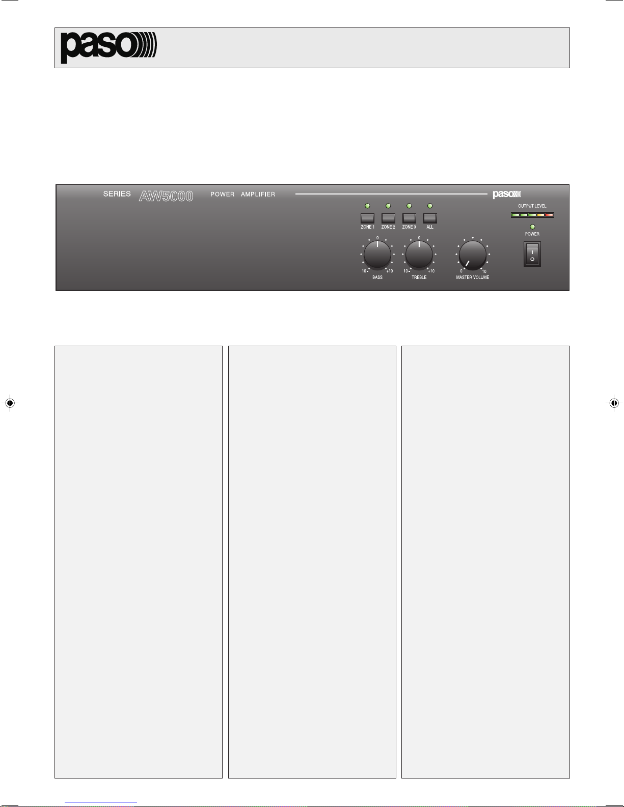
1.1 PANNELLO FRONTALE
Selettori delle zone.
[1]
[2] Visualizzatore del livello di uscita.
[3] Spia daccensione.
[4] Interruttore di rete.
[5] Controllo di volume generale.
[6] Controlli di tono.
7 8 11 12 13910
600
1V 1W
W
MOHOUTPUT TEL
FUSE T2,5A
CONSUMPT. 350 W
CONSUM T. 200 W
COM COMCOM V INZ2 Z3Z1
24V COM 50V 70V 100 V
8
W
8
W
POWER AMPLIFIER
GCOMHOT
LEV.LEV.
POWER AMPLIFIER AW5120
CHIME
OUTPUT
ZONE 1 ZONE 3ZONE 2 ALL
0
10
BASS
0
+10
10
TREBLE
1.1 FRONT PANEL
Zone selection switches.
[1]
[2] Output level indicator.
[3] ON/OFF signalling lamp.
[4] Mains switch.
[5] General volume control.
[6] Tone controls.
S.p.A. -ITALY
P
+
PRIORITY
INPUT
OUTPUT LEVEL
POWER
0
+10
MASTER VOLUME
10
4563
1.2 PANNELLO POSTERIORE
Selettore della tensione di rete.
[7]
[8] Regolazione livello uscita MUSIC ON HOLD.
[9] Uscite di linea e di potenza (1W/8Ω) MUSIC ON HOLD.
[10] Ingresso telefonico bilanciato.
[11] Regolazione livello ingresso telefonico.
[12] Chime ON/OFF.
[13] Morsettiera per contatto di precedenza.
[14] Presa di aerazione ventola di raffreddamento.
[15] Ingresso di linea.
[16] Uscita di linea.
Morsettiera per zone selezionate.
[17]
[18] Morsettiera uscite altoparlanti.
[19] Morsettiera per alimentazione esterna in corrente continua.
[20] Connessione telaio.
[21] Spina di rete con fusibile incorporato.
1.2 REAR PANEL
[7]
[8] MUSIC ON HOLD output level adjustment.
[9] MUSIC ON HOLD line and power outputs (1W/8Ω).
[10] Balanced telephone input.
[11] Telephone input level adjustment.
[12] Chime ON/OFF.
[13] Terminal strip for precedence contact.
[14] Cooling fan air intake.
[15]
[16] Line output.
[17] Terminal strip for selected zones.
[18] Loudspeaker output terminal strip.
[19] Terminal strip for external DC power supply.
[20] Frame connection.
[21] Mains plug with built-in fuse.
SERIE 5000
1416 151718192021
Mains voltage selector switch.
Line input.
3
GENERAL WARNINGS2AVVERTENZE GENERALI
2.1 INSTALLAZIONE
Tutti gli apparecchi PASO sono costruiti nel rispetto delle più severe
normative internazionali di sicurezza ed in ottemperanza ai requisiti
della Comunità Europea. Per un corretto ed efficace uso dellapparecchio
è importante prendere conoscenza di tutte le caratteristiche leggendo
attentamente le presenti istruzioni ed in particolare le note di sicurezza.
Durante il funzionamento dellapparecchio è necessario assicurare
unadeguata ventilazione. Evitare di racchiudere lapparecchio in un
mobile privo di aerazione o di ostruire le fessure di ventilazione ed in
particolare la presa daria posteriore della ventola di raffreddamento.
Evitare inoltre di tenere lapparecchio in prossimità di sorgenti di calore.
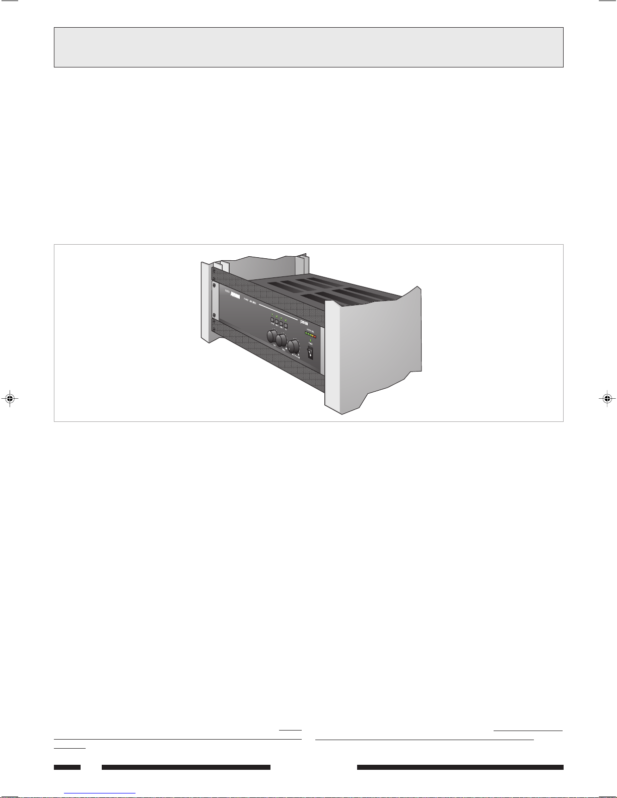
Questo apparecchio è predisposto per il montaggio in mobile rack standard
19 tramite luso dellaccessorio opzionale AC55.
É comunque consigliabile interporre un pannello di aerazione tra un
apparecchio e laltro (vedi fig. 2.1.1).
2.1 INSTALLATION
All PASO equipment is manufactured in accordance with the most
stringent international safety standards and in compliance with European
Community requisites. In order to use the equipment correctly and
effectively, it is important to be aware of all its characteristics by reading
these instructions and in particular the safety notes carefully.
While the equipment is working, it is necessary to provide adequate
ventilation. Do not close this equipment inside an unventilated cabinet
and do not obstruct the air vents, in particular not the air intake on the
rear for the cooling fan.
Do not keep the equipment in the vicinity of sources of heat.
This equipment can be equipped for mounting in a standard 19 by
means of the optional accessory AC55.
It is recommended that you place a ventilation panel between one
piece of equipment and the next (see Figure 2.1.1).
Fig. 2.1.1
2.2 ALIMENTAZIONE
Questo apparecchio è predisposto per il funzionamento con tensione di
rete a 230 V ± 10% 50/60 Hz. È possibile utilizzare lapparecchio anche
con una tensione di rete di 115 V ± 10% 50/60 Hz; a tal scopo è
necessario portare il selettore [7] in posizione 115 V.
Gli amplificatori della Serie 5000 possono anche essere alimentati con
una sorgente esterna di corrente continua con tensione di 24V che
deve essere applicata, rispettando le polarità, ai relativi terminali della
morsettiera [19]. In accordo con le normative di sicurezza, linterruttore
di accensione [4] agisce solo sulla tensione di rete.
In dotazione allapparecchio é fornito un cavo di alimentazione con filo
di terra; il terminale di terra della spina di rete non deve essere rimosso
in alcun caso.
Collegare la spina di rete [21] dellapparecchio alla rete elettrica
utilizzando lapposito cavo fornito in dotazione; assicurarsi che la presa
di corrente sia dotata di collegamento di terra a norma di legge.
Lapparecchio è protetto da due fusibili (vedi par. 4.4).
2.3 NOTE DI SICUREZZA
Ogni intervento allinterno dellapparecchio, quale la selezione di alcuni
modi duso o la sostituzione di fusibili, deve essere effettuato solo da
personale specializzato: la rimozione del coperchio rende accessibili
parti con rischio di scosse elettriche.
Prima di rimuovere il coperchio accertarsi sempre che il cavo di rete sia
staccato.
Nel caso di accidentale caduta di liquidi sullapparecchio, staccare
immediatamente la spina di rete ed interpellare il centro di assistenza
PASO più vicino.
La connessione di telaio [20] consente di collegare altre apparecchiature
per la sola funzione di schermatura dei segnali a basso livello:
presa non deve essere utilizzata per il collegamento di sicurezza del telaio
alla terra.
questa
2.2 POWER SUPPLY
This equipment is designed for use with a mains voltage of 230 V ± 10%
50/60 Hz. It is also possible to use the equipment with a mains voltage
of 115 V ± 10% 50/60 Hz, however in this case it is necessary to
position the selector switch [7] on 115 V.
The amplifiers of the 5000 Series can also be powered by means of an
external DC power supply with a voltage of 24V, which has to be applied
to the appropriate terminals on the terminal strip [19] paying attention
to the correct polarity. As required under safety regulations, the
ON/OFF switch [4] only controls the mains voltage.
The equipment is supplied with its own power-supply cable, which is
equipped with an earthing wire. The earth terminal of the mains plug
should never be removed under any circumstances.
Connect the mains plug [21] of the equipment to the power mains using
the cable included in the supply. Make sure that the power outlet is
equipped with a connection to earth in accordance with the law.
The equipment is protected by two fuses (see point 4.4).
2.3 SAFETY NOTES
Any activities inside the apparatus, such as selecting some of the
operating modes, the installation of accessories or the replacement
of fuses, must be carried out by specialized personnel only: when the
cover is removed, parts liable to cause electric shocks are exposed.
Before removing the cover, always make sure that the power cord
has been disconnected.
In the event that liquid is accidentally spilt onto the apparatus,
disconnect the mains plug immediately and contact the nearest PASO
Service Centre.
The chassis connection [20] may be used to connect other equipment
only for the purpose of shielding the low signals:
be used to connect the chassis to earth for safety purposes.
this socket may not
4
SERIE 5000

CONNECTIONS3CONNESSIONI
3.1 CRITERI GENERALI
Per un corretto funzionamento dellapparecchio è opportuno osservare
alcuni criteri di massima nellesecuzione dei collegamenti:
evitare il posizionamento di cavi e di microfoni sul mobile
dellapparecchio.
evitare di stendere le linee di segnale parallele a quelle di rete;
osservare una distanza minima di 30/40 cm.
posizionare le linee di ingresso e le linee di uscita distanti tra loro.
posizionare i microfoni al di fuori dellangolo di radiazione dei diffusori
sonori per evitare il fenomeno di reazione acustica (effetto Larsen).
3.2 INGRESSO/USCITA DI LINEA
Sul pannello posteriore dellapparecchio è disponibile lingresso di linea
INPUT [15] dellunità di potenza: per il collegamento sono disponibili, a
seconda delle esigenze, una presa XLR femmina oppure una presa per
spinotto jack da 1/4. La spina XLR maschio e la presa per spinotto jack
da 1/4 OUTPUT [16] riportano lo stesso segnale presente alla presa
INPUT, per un facile collegamento in cascata tra più unità di potenza.
Lo stadio dingresso è di tipo bilanciato, per cui è possibile effettuare
collegamenti sia di tipo bilanciato che sbilanciato.
La figura 3.2.1 riporta le connessioni, viste dallesterno.
COLLEGAMENTO BILANCIATO - BALANCED CONNECTION
1 = schermo / shield
2 = segnale (lato caldo) / signal (hot side)
3 = segnale (lato freddo) / signal (cold side)
COLLEGAMENTO SBILANCIATO - UNBALANCED CONNECTION
3.1 GENERAL FEATURES
For proper unit operation, use the following instructions when making
the connections:
Do not place cables or microphones on the unit cabinet;
Do not lay signal lines parallel to power lines; ensure a minimum
distance of 30/40 cm between them;
Keep input lines and the output lines far apart;
Keep the microphones outside the operating span of the speakers to
avoid acoustic feedback (Larsen effect).
3.2 LINE INPUT/OUTPUT
The line INPUT [15] for the power unit is situated on the rear panel of
the equipment. Depending on requirements, two sockets are available:
a female XLR socket and a socket for a ¼" jack. The male XLR plug and
the socket for the ¼" OUTPUT jack [16] relay the same signal available
on the INPUT socket, to make it easier to connect several power units
in cascade formation.
The input stage is of the balanced type, and it is therefore possible to
make both balanced and unbalanced connections.
Figure 3.2.1 shows the connections, seen from outside.
1 = segnale (lato caldo) / signal (hot side)
2 = segnale (lato freddo) / signal (cold side)
3 = schermo / shield
1 = schermo e massa / shield and
2 = schermo e massa / shield and GND
3 = segnale / signal
GND
Fig. 3.2.1
3.3 INGRESSO TELEFONICO
Lapparecchio è predisposto per il collegamento ad un sistema telefonico
tramite la morsettiera TEL [10]. Tale ingresso è bilanciato a
trasformatore, possiede un proprio controllo di livello - LEV. [11] - ed è
dotato di circuito VOX per la diffusione dei messaggi con priorità più
elevata rispetto a qualsiasi altro ingresso.
Lingresso telefonico consente inoltre il collegamento dellapparecchio alle
basi preamplificate PASO mod. B611. Per questo è necessario rimuovere
lo spinotto pentapolare DIN dal cavo della base e con i fili realizzare i
collegamenti illustrati in fig. 3.3.1. Tale configurazione consente anche
linvio di un segnale di preavviso (vedi par. 3.5).
IMPORTANTE: per questo tipo di collegamento è
INDISPENSABILE
chiudere tramite un ponticello i contatti [G] e [COM] della morsettiera
TEL [10].
.SOP
1 OMREHCS DLEIHS
2 OREN KCALB [ MOC ]
3 OCNAIB ETIHW [ TOH ]
4 OSSOR DER
5 EDREV NEERG [P]
OVAC
ELBAC
AREITTESROM
PIRTSLANIMRET
"LET"
"YTIROIRP"
[G]
[+]
ELANIMRET
LANIMRET
1 = segnale / signal
2 = schermo e massa / shield and
GND
3.3 TELEPHONE INPUT
The equipment has provisions for connection of a telephone system by
means of the TEL terminal strip [10]. This input is balanced by a
transformer, has its own level control - LEV. [11] - and is equipped with
a VOX circuit for broadcasting messages with a higher priority level than
any other input.
The telephone input also enables the equipment to be connected to the
PASO mod. B611 preamplified bases. To do this, it is necessary to remove
the five-pole DIN plug from the cable on the base and use the wires to
make the connections illustrated in Figure 3.3.1. This configuration also
enables a warning signal to be sent (see point 3.5).
IMPORTANT: For this type of connection it is
ESSENTIAL to close the
contacts [G] and [COM] of the TEL terminal strip [10] with a jumper.
Fig. 3.3.1
SERIE 5000
5
3CONNESSIONI
CONNECTIONS
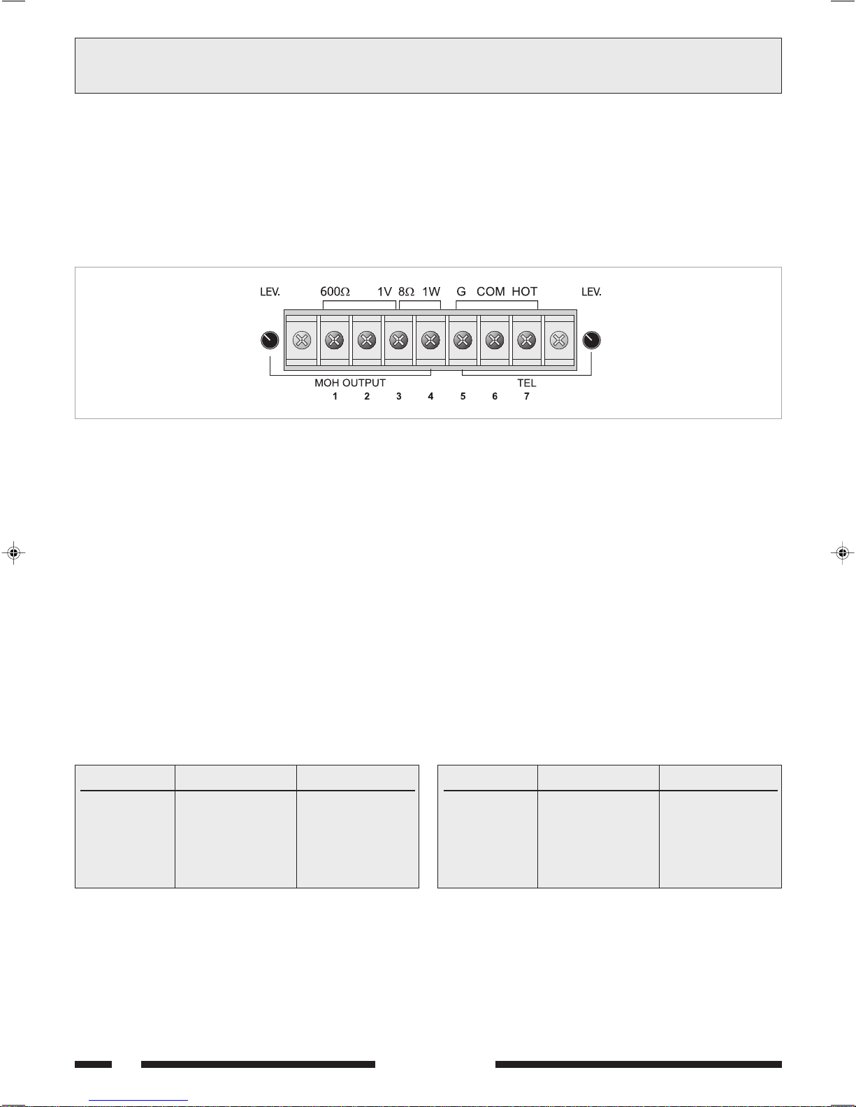
3.4 USCITA MUSIC ON HOLD (MOH)
A questi morsetti [9] e' disponibile il segnale presente allingresso INPUT
[15]; tale segnale non e' soggetto allazione di precedenza microfonica o
telefonica. In particolare, l'uscita bilanciata a trasformatore (morsetti
1-2-3 di fig. 3.4.1) puo' essere utilizzata per il pilotaggio di un ulteriore
amplificatore, di un centralino telefonico od altro; l'uscita di potenza
(morsetti 3-4 di fig. 3.4.1) e' in grado di pilotare direttamente un piccolo
altoparlante monitor da 8 Ω con potenza massima di 1 W.
É possibile regolare il livello di uscita agendo sul controllo LEV. [8].
1: 600Ω (linea - lato caldo)
2: 600Ω (linea - lato freddo)
3: massa e schermo
4: 1W/8Ω uscita altoparlanti
3.5 PRECEDENZA E SEGNALE DI PREAVVISO
Chiudendo i contatti della morsettiera PRIORITY [13] viene
ammutolito il segnale presente all presa INPUT [15]; la chiusura del
contatto genera un segnale di preavviso a due toni (CHIME) se il selettore
CHIME [12] si trova in posizione ON.
É possibile modificare il livello del segnale di preavviso agendo sul trimmer
semifisso VR301 posto sul circuito Priority (vedi par. 2.3).
(line - warm side)
(line - cold side)
GND and shield
loudspeakers output
Fig. 3.4.1
3.4 MUSIC ON HOLD OUTPUT (MOH)
The signal available on INPUT [15] is also available on these terminals
[9]. This signal is not affected by the use of telephone precedence.
In particular, the balanced transformer output (strips 1-2-3, Fig. 3.4.1)
can be used to drive an additional amplifier, a telephone exchange or
other equipment. The power output (terminals 3-4 in Figure 3.4.1) is
capable of driving directly a small 8 Ω monitoring loudspeaker with a
maximum output of 1 W.
It is possible to adjust the output level by means of the LEV.
control [8].
5: TEL (massa schermo)
(
GND and shield)
6: TEL (ingresso - lato freddo)
(input - cold side)
7: TEL (ingresso - lato caldo)
(input - warm side)
3.5 PRIORITY AND WARNING SIGNAL
If the contacts of the PRIORITY terminal strip [13] are closed, the
signal on the INPUT socket [15] is muted. Closing the contact causes a
two-tone warning signal (CHIME) to be generated. The CHIME switch
[12] is in the ON position.
It is possible to change the level of the warning signal by means of the
semi-fixed trimmer VR301 on the Priority circuit (see point 2.3).
3.6 USCITE DI POTENZA
Le uscite di potenza per i diffusori sono disponibili sulla morsettiera [18].
È possibile realizzare un impianto di diffusione sonora utilizzando sia
diffusori a bassa impedenza, sia diffusori dotati di traslatore di linea.
In entrambi i casi il carico complessivo non deve essere tale da
sovraccaricare lamplificatore: non applicare cioè diffusori o gruppi di
diffusori con impedenza più bassa di quella nominale della presa alla
quale sono collegati. Si raccomanda inoltre di porre particolare attenzione
al calcolo delle impedenze nel caso si debbano realizzare impianti di
diffusione misti (a bassa impedenza e a tensione costante).
In tabella 3.6.1 sono riportati i valori nominali di tensione ed impedenza
per le diverse uscite.
Uscita
8 Ω
50 V
70 V
100 V
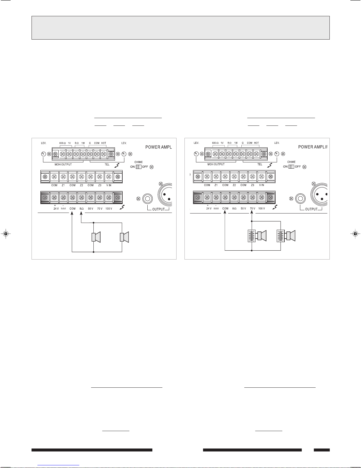
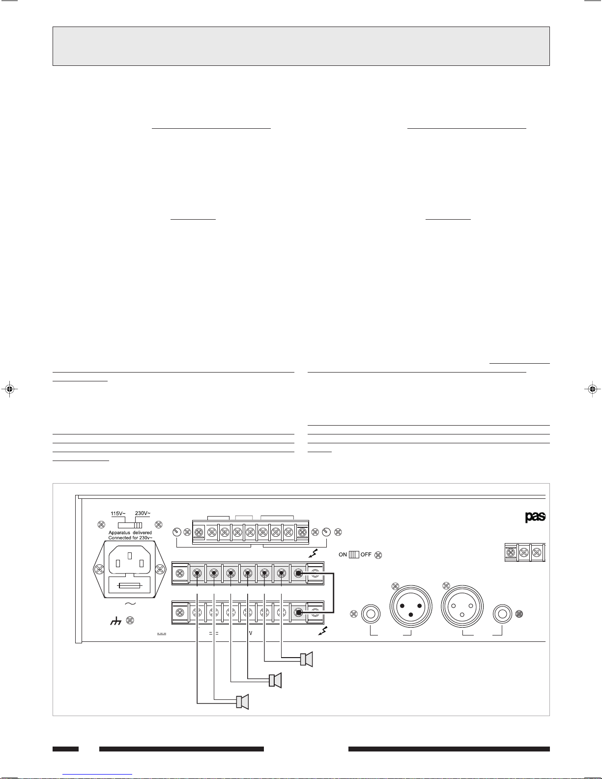
3.6.1 Sistemi a bassa impedenza
In applicazioni che richiedono luso di pochi altoparlanti, la linea di
collegamento può essere connessa tra il terminale comune 0 e la presa
ΩΩ
8
Ω della morsettiera [18].
ΩΩ
Il collegamento degli altoparlanti, di tipo serie o parallelo o misto, deve
fornire unimpedenza calcolata pari o superiore ad 8 Ω.
In figura 3.6.1 é riportato un esempio di collegamento.
AW5240
43,8 V
10,4 Ω
20,4 Ω
41,7 Ω
Tabella 3.6.1
AW5120
31 V
20,8 Ω
40,8 Ω
83,3 Ω
3.6 POWER OUTPUTS
The power outputs for the loudspeakers are available on the terminal
strip [18]. It is possible to set up a sound-broadcasting system
using either low-impedance loudspeakers or loudspeakers equipped with
a line transformer. In both cases the overall load must not be such as to
overload the amplifier. This means that you must not apply loudspeakers
or groups of loudspeakers with an impedance lower than the rated
impedance of the socket to which they are connected. It is also
necessary to pay particular attention to calculating the impedance values
if mixed broadcasting systems (low impedance and constant voltage)
are to be set up.
Table 3.6.1 shows voltage and impedance rated values for the various
outputs.
Output
8 Ω
50 V
70 V
100 V
3.6.1 Low-impedance systems
In applications that require the use only of a few loudspeakers, the
connecting line may be connected between the common terminal 0 and
ΩΩ
the 8
Ω socket of the terminal strip [18].
ΩΩ
The loudspeaker connection, whether of the serial or parallel type or
mixed, should provide an impedance calculated to be equal to or higher
than 8 Ω. An example of a connection is shown in Figure 3.6.1.
AW5240
43,8 V
10,4 Ω
20,4 Ω
41,7 Ω
Table 3.6.1
AW5120
31 V
20,8 Ω
40,8 Ω
83,3 Ω
6
SERIE 5000
CONNESSIONI
3
CONNECTIONS
Calcolo dellimpedenza nei collegamenti in serie
Nel caso di diffusori collegati in serie tra loro, limpedenza totale è la
somma delle singole impedenze:
impedenza totale = Z1 + Z2 + Z3 + ....
Calcolo dellimpedenza nei collegamenti in parallelo
Nel caso di diffusori collegati in parallelo tra loro, limpedenza totale può
essere determinata mediante la seguente formula:
impedenza totale =
1
+
Z11 Z2
1
1
+ + ......
Z3
Calculating the impedance value in series connections
In the case of loudspeakers connected to one another in series, the total
impedance is the sum of the single impedance values:
Total impedance = Z1 + Z2 + Z3 + ....
Calculating the impedance value in parallel connection
In the event of loudspeakers connected in parallel to one another the
total impedance can be calculated by means of the following formula:
Total impedance =
1
+
Z11 Z2
1
1
+ + ......
Z3
ΩΩ
Ω
ΩΩ
Fig. 3.6.1
3.6.2 Sistemi a tensione costante
Nel caso di impianti con un gran numero di diffusori e/o con distanze tra
amplificatori ed altoparlanti molto elevate é preferibile utilizzare un sistema
di distribuzione a tensione costante (definito anche ad alta impedenza).
In questo tipo di impianto, i diffusori, provvisti di trasformatori di
adattamento di impedenza, sono tutti collegati in derivazione alla linea
(vedi es. di Fig. 3.6.2); questo particolare rende di facile realizzazione
limpianto e, nel caso in cui un altoparlante dovesse per qualche motivo
scollegarsi dalla linea, il resto dellimpianto proseguirebbe nel suo regolare
funzionamento. Le tensioni costanti disponibili in uscita dallamplificatore
sono 50, 70 e 100 V.
Calcolo del numero di diffusori (tramite le potenze)
Si supponga di avere definito sia l'amplificatore (cioè la sua potenza di
uscita) che il tipo di diffusore con relativa potenza assorbita.
In questo caso il massimo numero di diffusori collegabile sulla linea è
determinato dalla seguente formula:
numero diffusori =
Esempio: si utilizzino un amplificatore AW5240 con plafoniere modello
Paso C42. L'amplificatore è in grado di erogare una potenza pari a
240 W, mentre un diffusore assorbe una potenza di 6 W.
Per sapere quanti diffusori sono collegabili alla linea di uscita si calcola:
numero diffusori = = 40
potenza amplificatore
potenza diffusore
240 W
6 W
16
ΩΩ
Ω16
ΩΩ
20W 20W
Fig. 3.6.2
3.6.2 Constant voltage systems
When a large number of speakers is used and/or the speakers are
placed far from the amplifiers, constant voltage distribution system
should be used (also known as high-impedance systems).
In this type of system, the speakers are fitted with impedance
adaptation transformers and all of them have shunt line connections
(see example of Fig. 3.6.2). This simplifies the layout of the system and
if, for any reason, a loudspeaker is disconnected from the line, the rest
of the system will continue to work properly. The constant voltages
output from the amplifier are 50, 70 and 100 V.
Determining the number of speakers (through power values)
If both the amplifier (i.e. its output power) and the type of speaker
with its power consumption have been established, the maximum number
of speakers which may be connected to the line may be determined as
follows:
number of speakers =
Example: in a system including a AW5240 amplifier with ceiling
speakers type Paso C42 is used, the amplifier can supply 240 W power
whereas the speaker has a power consumption of 6 W.
The number of speakers which may be connected to the output line is
number of speakers = = 40
amplifier power
speaker power
240 W
6 W
SERIE 5000
7
CONNECTIONS3CONNESSIONI
f
Calcolo del numero di diffusori (tramite le impedenze)
Se il dato disponibile è l'impedenza del diffusore, il numero massimo di
diffusori collegabili ad una linea è:
numero diffusori =
impedenza diffusore
impedenza amplificatore
dove l'impedenza nominale dell'amplificatore è ricavabile dalla
tabella 3.6.1.
Esempio: si utilizzino un amplificatore AW5240 con diffusori tipo
Paso C55, che presentano una impedenza pari a 500 ohm.
Dalla tabella 3.6.1 si trova che l'impedenza nominale di carico della linea
a 100 V è pari a 41,7 ohm.
Quindi:
numero diffusori = = 12
500 Ω
41,7 Ω
NOTA BENE: nel caso più generale in cui i diffusori sono di diverso tipo
e/o collegati con differente potenza, è importante verificare sempre che
la potenza complessiva richiesta dai diffusori (ottenuta semplicemente
dalla somma delle singole potenze) sia inferiore a quella nominale
dellamplificatore.
3.7 SELEZIONE DI ZONE DASCOLTO
Gli amplificatori della Serie 5000 dispongono della possibilità di
inserire/disinserire in modo indipendente fino a tre zone di diffusione
tramite gli interruttori ZONE 1, ZONE 2 e ZONE 3 [1]. In questo caso,
le tre zone di diffusori devono essere connesse alla morsettiera [17],
tenendo sempre conto del carico nominale massimo ammesso
dallapparecchio.
É inoltre possibile selezionare contemporaneamente tutte le zone dascolto
tramite linterruttore ALL. Le selezioni effettuate tramite gli interruttori
[1] sono confermate dallaccensione delle relative spie luminose.
Gli interruttori interrompono il collegamento delle linee a tensione
costante sui terminali della morsettiera [17].
La selezione della tensione di linea per le zone deve essere effettuata
collegando tramite uno spezzone di filo il terminale V IN della morsettiera
[17] al terminale corrispondente alla tensione desiderata sulla
morsettiera [18]. In fig. 3.7.1 è riportato un esempio di collegamento a
tre zone di diffusione con tensione di linea 100 V.
Determining the number of speakers (through impedance)
If the impedance of the speaker is known, the maximum number o
speakers which may be connected to the line is:
number of speakers =
speaker impedance
amplifier impedance
where the amplifier rated impedance may be determined referring to
Table 3.6.1.
Example: If a AW5240 amplifier is used with speakers type Paso
C55 having a 500 ohm impedance, the rated load impedance of the
line at 100 V may be determined from Table 3.6.1 as being equal to
41,7 ohm.
Thus
number of speakers = = 12
500 Ω
41,7 Ω
N.B.: In the more general case of a system including loudspeakers of
different types or connected with different outputs, it is always important
to make sure that the overall power required by the loudspeakers (which
can be calculated simply by adding up the output power of the single
units) is lower than the rated power of the amplifier.
3.7 SELECTING THE LISTENING AREAS
With the amplifiers of the 5000 Series it is possible to include or
exclude up to three broadcasting areas separately, using the ZONE 1,
ZONE 2 and ZONE 3 switches [1]. In this case, the three loudspeaker
areas must be connected to the terminal strip [17], always taking the
maximum permissible rated load for the equipment into account.
It is also possible to select all the listening areas at the same time by
means of the ALL switch. The selections made by means of the switches
[1] are confirmed by the relevant signalling lamps lighting up.
These switches cut off the constant voltage lines on the terminals of
the terminal strip [17].
The line voltage for the various zones has to be selected by connecting
the V IN terminal of the terminal strip [17] to the terminal corresponding
to the required voltage on the terminal strip [18] by means of a length
of wire. An example of connection to three broadcasting zones with a
line voltage of 100 V is shown in Figure 3.7.1.
MOH OUTPUT TEL
COM COMCOM
FUSE T2,5A
CONSUMPT. 350 W
CONSUM T. 200 W
24 V COM 50 V 70 V 100 V
8
600
Z1
1V 1W
W
8
W
Z2
8
GCOMHOT
W
ZONE 1
Z3
VIN
ZONE 2
Fig. 3.7.1
SERIE 5000
LEV.LEV.
ZONE 3
POWER AMPLIFIER
CHIME
OUTPUT
AW5120
INPUT
P
+
PRIORITY

OPERATION4USO DELLAPPARECCHIO
4.1 ACCENSIONE
Prima di mettere in funzione l'apparecchio accertarsi di avere realizzato
tutte le connessioni necessarie al completamento dell'impianto e di aver
effettuato le impostazioni di funzionamento.
Portare l'interruttore di rete [4] in posizione ON.
La spia luminosa POWER [3] confermerà l'accensione dell'apparecchio.
Se necessario, regolare il livello di ascolto tramite il controllo MASTER
VOLUME [5] e ritoccare il livello del segnale telefonico rispetto a quello
presente allingresso INPUT [15] per una corretta equalizzazione tramite
la regolazione LEV. [11].
4.2 CONTROLLO DI VOLUME PRINCIPALE
Il controllo di volume principale MASTER VOLUME [5] regola il livello
complessivo del segnale di uscita, derivato dalla miscelazione dei vari
segnali di ingresso. Per ottenere in uscita un segnale privo di distorsione,
si raccomanda di controllare che sull'indicatore del livello di uscita [2]
non si accenda la spia di colore rosso (+1 dB) o, comunque, che ciò
avvenga saltuariamente; in caso contrario, è necessario diminuire il
livello di uscita agendo sul comando MASTER VOLUME [5].
La potenza di uscita nominale è segnalata dall'accensione della spia
luminosa gialla (0 dB).
4.3 CORREZIONE ACUSTICA
I controlli BASS e TREBLE [6] modificano la tonalità del segnale di
uscita derivato dalla miscelazione dei vari segnali di ingresso.
Controllo toni bassi (BASS)
Il controllo BASS regola le prestazioni dell'amplificatore alle basse
frequenze. La posizione di centro, indicata dallo 0, fornisce una risposta
lineare; per avere una esaltazione delle frequenze basse ruotare la
manopola in senso ORARIO. Utilizzando diffusori a tromba è opportuno
tramite il comando BASS, attenuare le frequenze basse; un eccessivo
livello delle basse frequenze potrebbe danneggiare la membrana del
diffusore.
Controllo toni acuti (TREBLE)
Il controllo TREBLE regola le prestazioni acustiche dell'amplificatore alle
alte frequenze. La posizione di centro, indicata dallo 0, fornisce una
risposta di tipo lineare; per avere una esaltazione delle frequenze alte
ruotare la monopola in senso ORARIO. Lattenuazione dei toni acuti è
utlie per minimizzare un eccessivo livello di fruscio o per rendere più dolci
suoni particolarmente sibilanti.
4.1 POWER ON
Before starting up the equipment, make sure that all the connections
required for completing the system have been made and that all the
settings for correct operation have been made.
Set the mains switch [4] to the ON position.
The POWER [3] LED lights up, when the unit is switched on.
If necessary, adjust the listening volume by means of the MASTER
VOLUME control [5] and adjust the level of the telephone signal in
relation to the signal available on the INPUT [15] for correct equalisation,
using the LEV. control [11].
4.2 MASTER VOLUME CONTROL
The MASTER VOLUME control [5] adjusts the output signal overall
level as generated by mixing different input signals.
To obtain a flutter-free output signal, check that the red LED indicator
(+1 dB) on the output level indicator [2] is not on, or at any rate that
it does not light up frequently; otherwise, the output level should be
reduced by the MASTER VOLUME control [5].
The rated output power is reached when the yellow LED indicator (0 dB)
lights up.
4.3 ACOUSTIC ADJUSTMENT
The BASS and TREBLE controls [6] adjust the output signal tone
generated by mixing the different input signals.
Bass control (BASS)
The BASS control adjusts the amplifier performance at low frequencies.
The center position 0 provides a linear response.
To emphasize low frequencies, turn the knob clockwise; to attenuate
them, turn the knob CLOCKWISE. When horn-type speakers are used,
low frequencies should be attenuated by means of the BASS control.
An excessive low frequency level could damage the speaker diaphragm.
Treble control (TREBLE)
The TREBLE control adjusts the amplifier performance at high
frequencies. The center position 0 provides a linear response.
To emphasize high frequencies, turn the knob clockwise; to attenuate
them, turn the knob CLOCKWISE.
Attenuation of the treble tones is useful for minimising and excessive
level of rustling or in order soften hissing sounds.
4.4 SOVRACCARICO E PROTEZIONE
Applicare un valore di impedenza di carico inferiore a quella nominale
significa richiedere all'apparecchio una potenza superiore a quella
erogabile con continuità. Questo potrebbe portare al danneggiamento
degli stadi finali di potenza e dei trasformatori di alimentazione e di uscita.
Per non incorrere in questi inconvenienti gli amplificatori della
Serie 5000 sono abbondantemente dotati di circuiti e dispositivi di
protezione contro i sovraccarichi ed i cortocircuiti:
- circuito limitatore di picco della corrente di uscita: il suo intervento è
istantaneo ed agisce tipicamente nel caso di sovraccarico.
- interruttore termico ripristinabile: posto a contatto del dissipatore dei
transistor di potenza, interrompe lalimentazione dei circuiti di pilotaggio,
e di conseguenza annulla il segnale di uscita, nel caso in cui la
temperatura dei finali raggiunga valori pericolosi. Il ripristino è
automatico non appena la temperatura rientra nel range di normale
funzionamento.
- fusibili di rete (accessibile sulla presa rete [21]) e di alimentazione
interna a bassa tensione (accessibile allinterno dellapparecchio, sul
circuito dalimentazione): questi dispositivi garantiscono il blocco
immediato del funzionamento dellamplificatore in caso di guasto interno
dello stesso.
Da segnalare infine che i modelli AW5120 e AW5240 sono dotati di
ventola di raffreddamento, con controllo automatico della velocità in
funzione della temperatura del dissipatore su cui sono applicati i dispositivi
di potenza.
4.4 OVERLOADING AND PROTECTION
Applying a load impedance value lower than the rated loan means that
the equipment is required to supply power in excess of the capacity that
can be delivered with continuity. This could lead to damage to the final
power stages and of the power supply and output transformers.
In order not to incur these upsets, the amplifiers of the 5000 Series
are equipped with a large number of circuits and devices protecting
them against overloads and short circuits:
- output current peak limiting circuit: this is tripped instantaneously and
- resettable thermal circuit-breaker: this is placed in contact with the
- Mains fuses (accessible on the mains plug [21]) and on the internal
It should be pointed out, lastly, that models AW5120 and AW5240 are
equipped with cooling fans with automatic control of the speed in relation
to the temperature of the heat sink to which the power devices are
applied.
SERIE 5000
its typical function is in the event of overloads.
heat sink of the power transistors. It cuts off power to the driving
circuits and therefore cancels the output signal if the temperature
of the end stages reaches hazardous levels. It resets automatically
as soon as the temperature returns to within the normal operating
range.
low-voltage power supply (accessible inside the equipment, on the
power supply circuit): these devices stop the amplifier working
immediately in case of internal failure inside it.
9
 Loading...