


Pasontech.com Present
E-Evolution
E-Power F3A Areobatics Airplane
For Intermediate & Advanced Fliers.
SAFETY PRECAUTIONS
This radio control model is not a toy!
Fist-time builders should seek advice from people having building
Experience in order to assemble the model correctly and to produce
Its performance to full extent.
Assemble this kit only in places out of children’s reach!
Take enough safety precautions prior to operating this model.
You are responsible for this model’s assembly and safe operation!
Always keep this instruction manual ready at hand for quick
Reference, even after completing the assembly.
Notice:
By the time the Yak arrives in your shop, it will have endured several climate changes.
As a result you may find some wrinkles in the covering and wing or Fus. Part maybe
have some twisted. This is not a manufacturing defect. Please take a few moments
with your iron or heat gun to remove any wrinkles and correct all twisted parts. Iron
over all the edges to ensure they are sealed.
This Products Produce by Pasontech Hobby Company
Room J, Floor 22 Baiheyindu building Buji town Longgang district Shenzhen China
E-mail: sales@pasontech.com http://www.pasontech.com
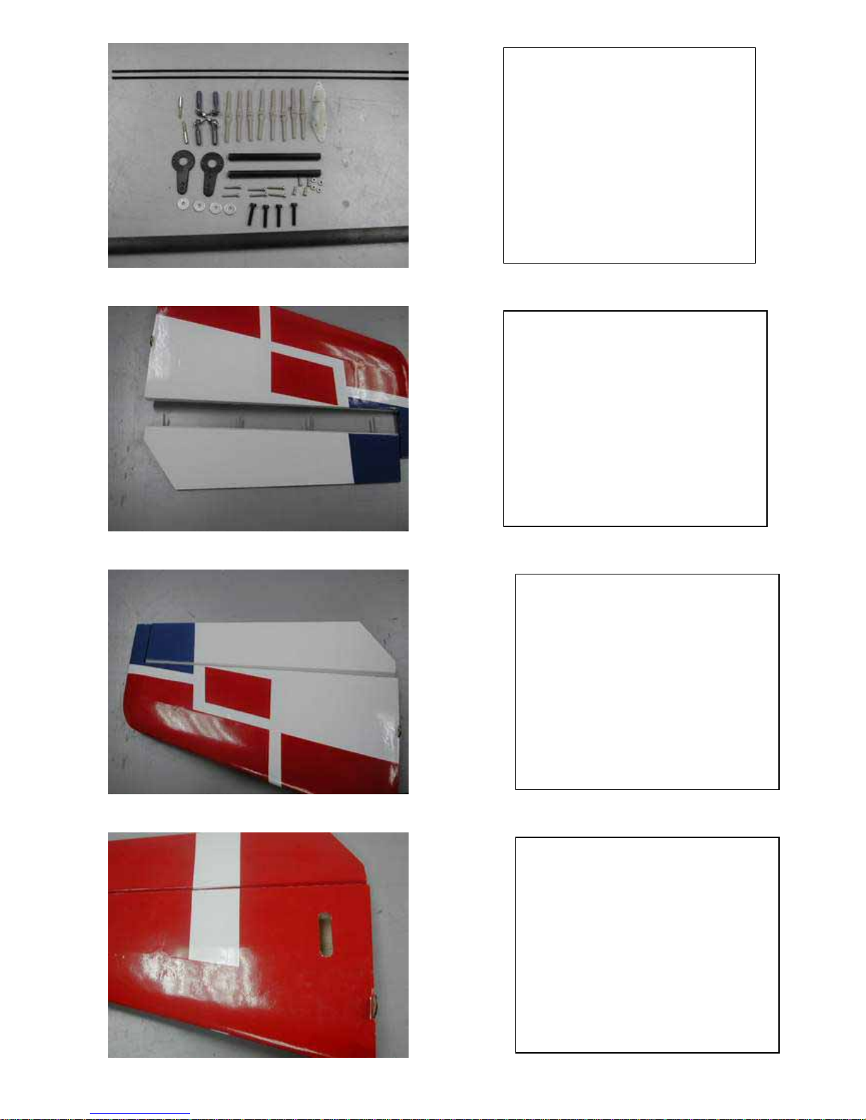
Find the Tail gear assemble parts as
show.
Cut out film as hole
Glue the four pin hinges with
Epoxy.
Install the tail gear wire in to the
gear mount.
Then bending the wire as the show.
Install the tail wheel and wheel
stopper as show.
Drill a 2mm hole into the exact
center of the rudder as marked to
accept the tail wheel wire.
Install the tail wheel wire to the
Rudder and
Glue the with Epoxy.
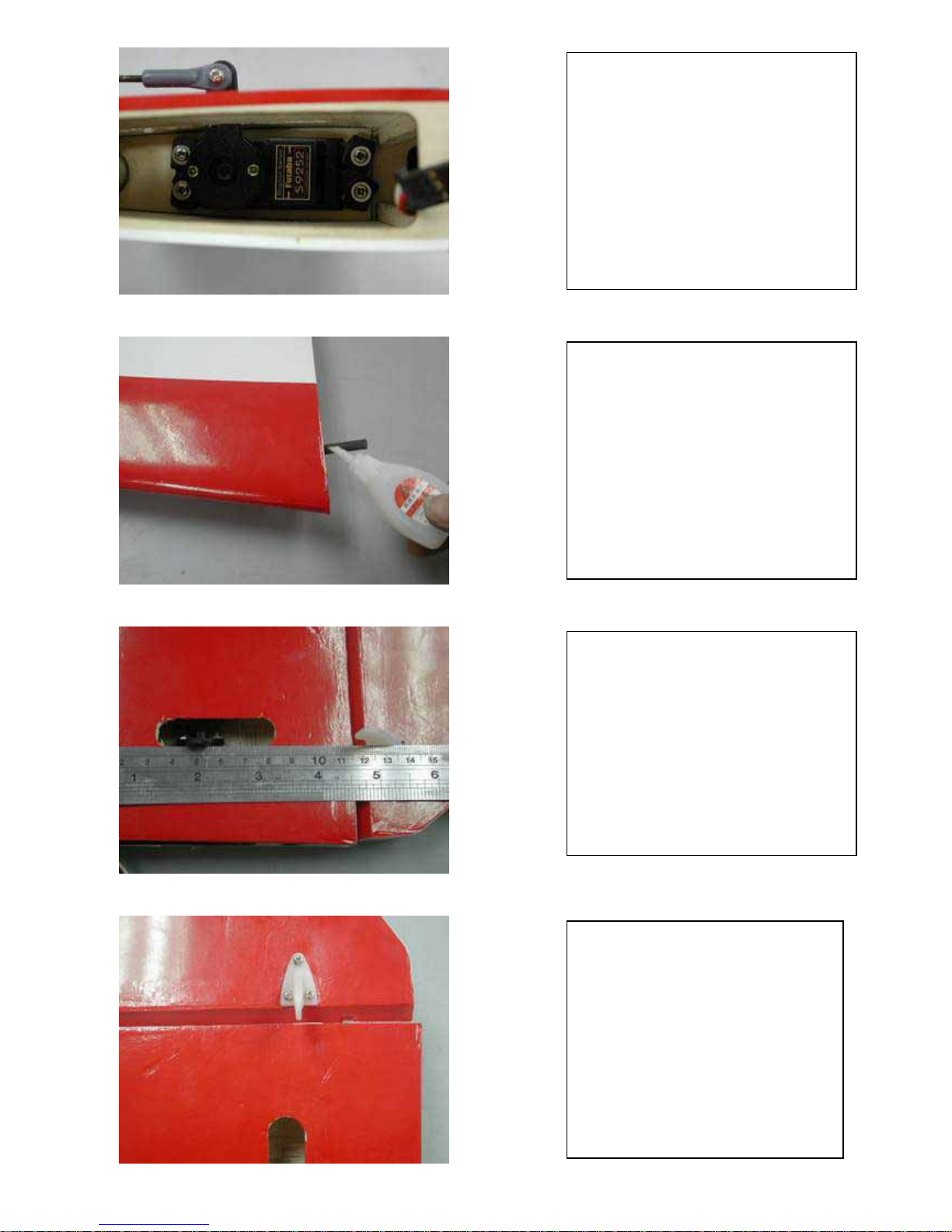
Install the Rudder to Fin and Fus.
Keep the Rudder and Fin top have
1mm grip .
Glue them in piece.
Drill four 1.0mm hole
Fix the tail gear with four 2X13mm
TP. Screw.
TP. Screw 2X13MM X4
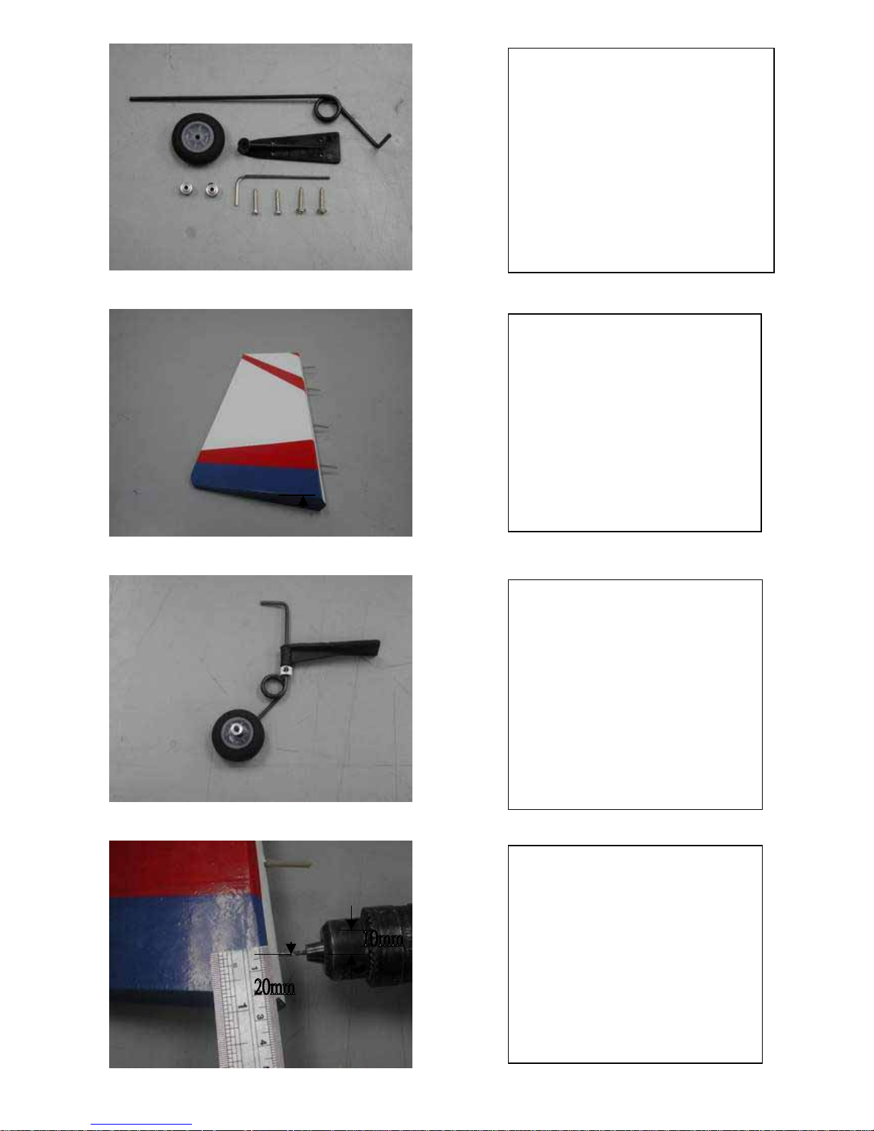
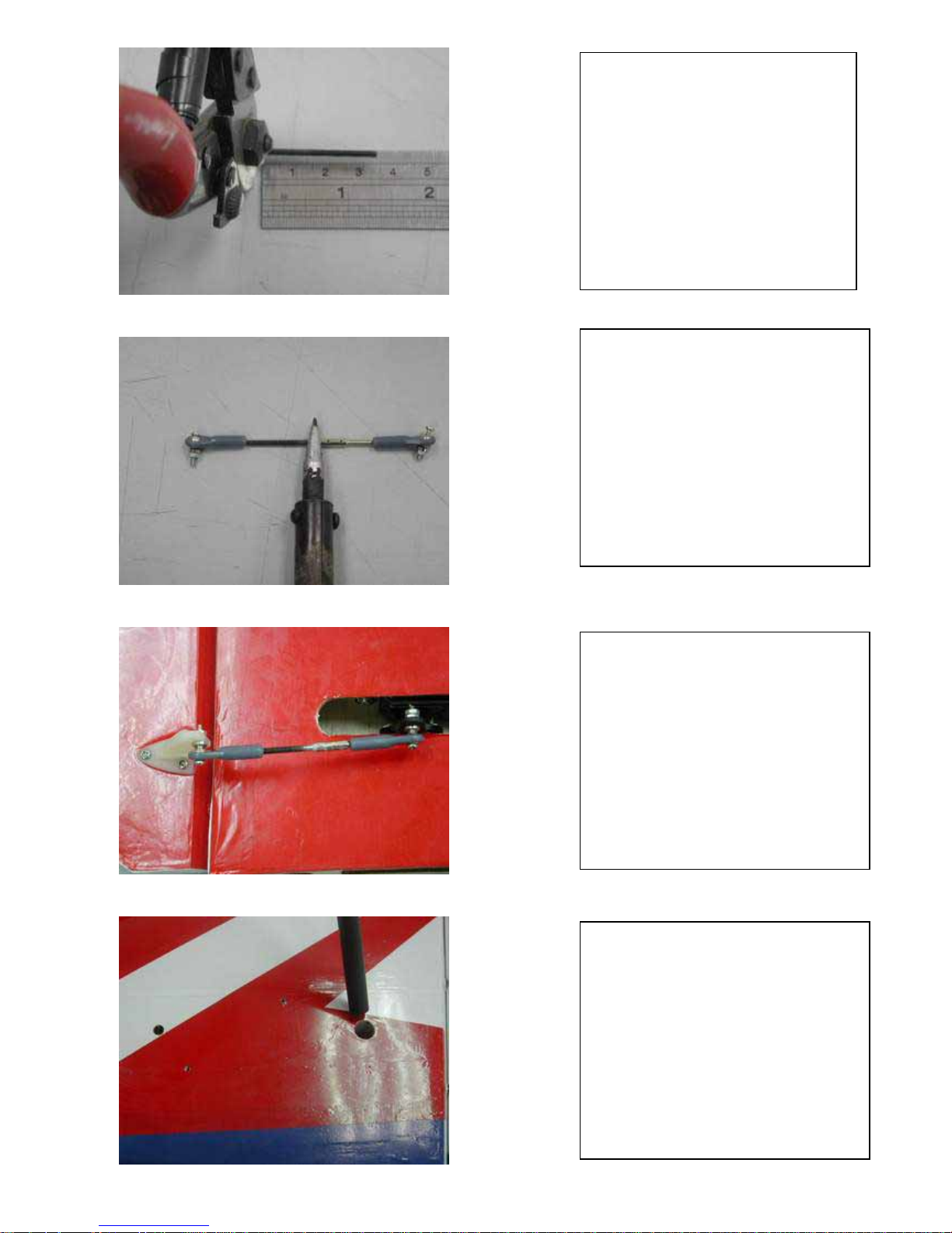
find the Rudder control parts as
show.
Trim off covering film as show.
.Check the Rudder control horn in
line as the wire outlet.
Install Rudder control as show
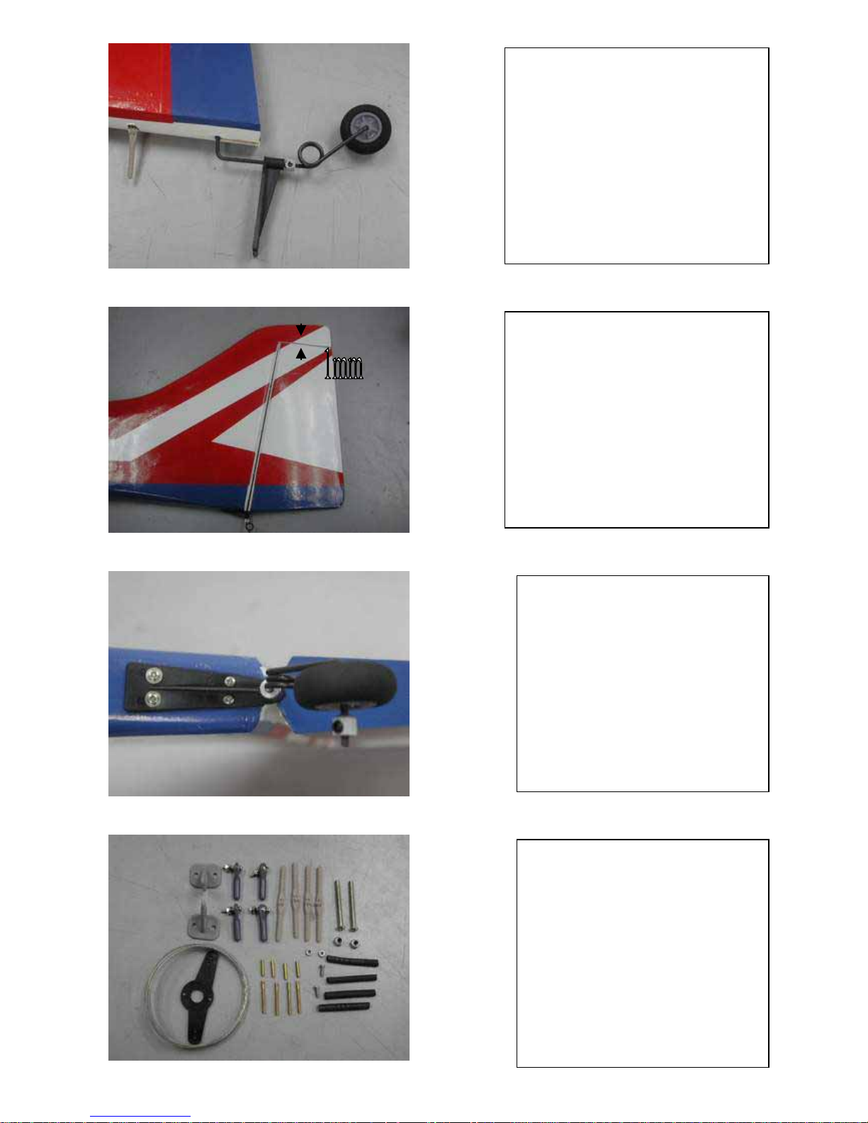
Assemble ball link end and wire as
show
Use any tool to made the wire stopper
p
ipe tight as show.
Use some heat to made the heat sink
tube to cover wire stopper pipe as
show.
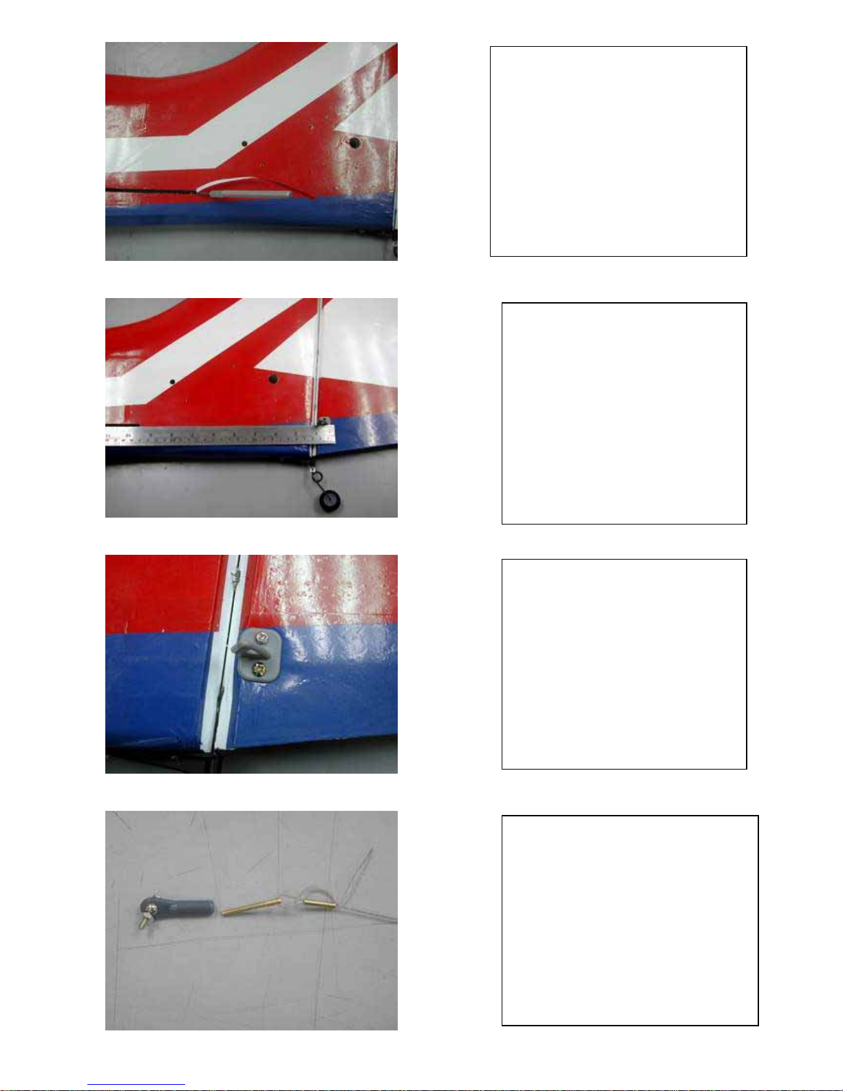
Install the ball link end with two M2
screw as show.
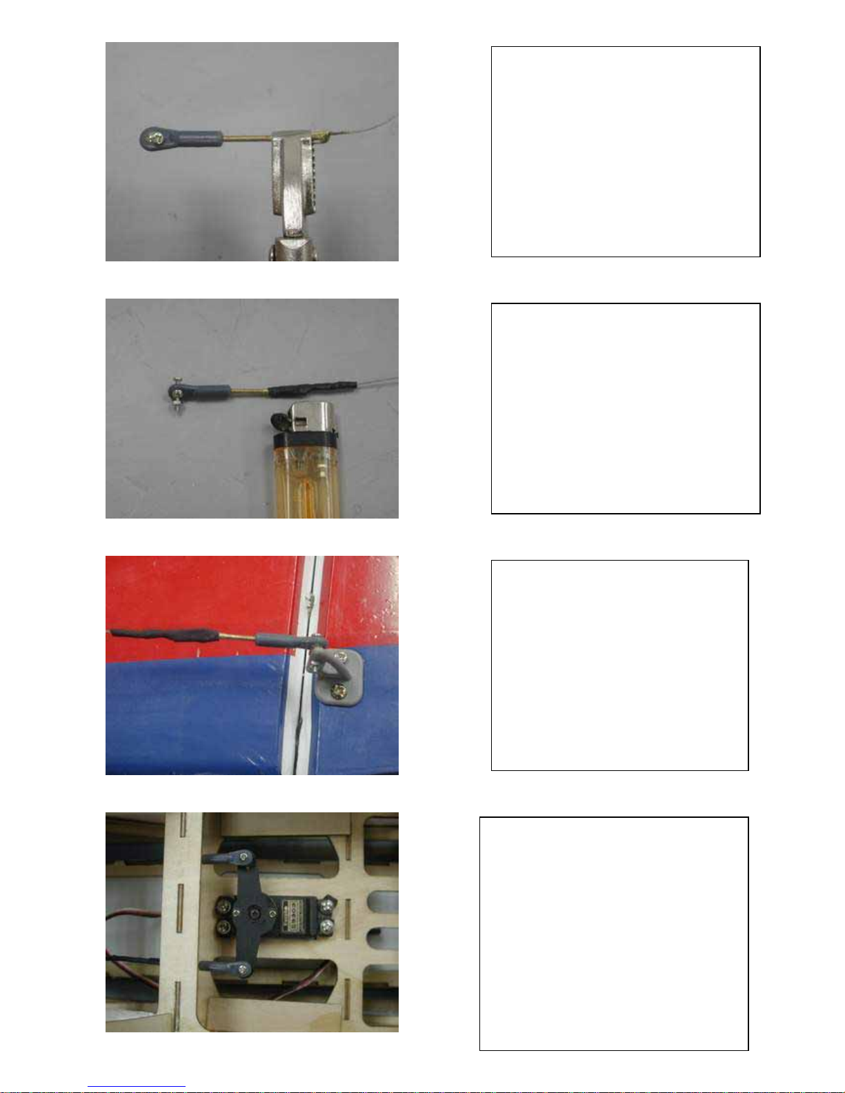
Use same way as Rudder Horn to
assemble Rudder servo horn as horn.
PIN hinges X8
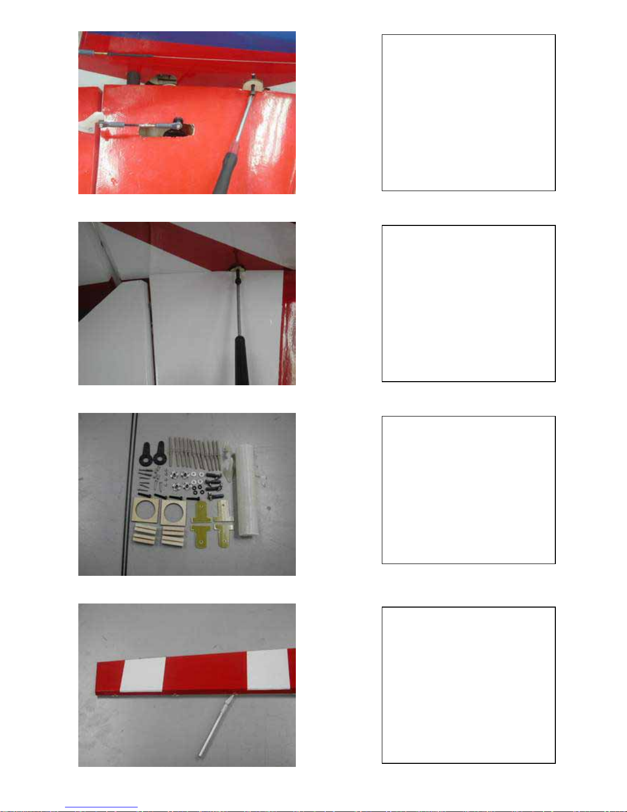
After check the last hinges will not
stop Stab. Join. Glue Stabilizer and
Elevator together with epoxy.
Cut the last two hinges 3mm shorter
So the last hinge will not stop the
Stab. Join inside the Stab.
glue four hinges to each Elevator.
.
glue four hinges to each Elevator to
each side Stabilizer.
At the Stabilizer bottom trim off the
film servo horn slot as show.
Elevator servo bay was inside
Stabilizer and it size was stander size
servo.
Install the carbon anti roll pin as
show to each Stabilizer and glue it
together with thick CA. or epoxy.
.
Check Elevator servo horn
And Elevator horn was inline.
Install the Elevator control horn as
show.
Cut the push rob to 35mm.
Use iron to solid the push rod
connector as show .
After the push rod cool down install
the ball link end as show.
Install the Elevator control push rob
as show.
Install the carbon join to Fus. as
show .
Install each Stabilizer on lower
side of the Fus. With four M3 X
15mm screw and washer.
Important notice: Please apply
“thread locker” before you install
Stab. Screw.
Connecting the servo lead before
you install the Stabilizer.
Install each Stabilizer on upper
side of the Fus. With four M3 X
15mm screw and washer.
Important notice: Please apply
“thread locker” before you install
Stab. Screw.
Connecting the servo lead before
you install the Stabilizer.
Find the Aileron linkage set as
show.
Install aileron linkage as the
show.
Trim off the covering film as
show.

Install and Glue seven pin hinge in
to each side Aileron.
Glue them in piece with epoxy.
PIN hinge X 7
Install each side Aileron. To each
side wing panel.
Glue them in piece with epoxy
Trim off the cover film at servo bay
area under each wing panel.
Check the aileron Control horn and
servo horn in line as show.

Install aileron Control horn the show.
Cut the push rob to 45mm.
Use iron to solid the push rod
connector as show .
After the push rod cool down
install the ball link end as show.

Install aileron Control push rob as
show.
find two wing hookup plate as
show.
Install the wing mount plate from
inside wing root at both LE. And
TE.

Gluethe wing mount plate from
inside wing root at both LE. And
TE. With Epoxy.
Use M3X 15mm screw to fix the
canopy.
N
otice: please use the “O” ring and
washer to made the canopy screw
not easy to loosing .
Before you install wing panel to
fus. Trim off the cover at wing
mount slot as show.
Follow the mount plate hole to drill
a 3mm hole then remove the wing
and made hold bigger for blind nut
as show.

Install blind nut on wing mount and
use screw to made the blind nut tight
as show.
We stronger recommended After
you find out the good CG. Point
for your flying style.
Reinforce your airplane with FRP.
Wing join tube and ply support.
Find the canopy and wire lock parts
as show.

Follow the slot to trim off covering
film for Fus. Side as show.
Install wire and glue wire and the
wood block in place as show.
Install the wire end cover as
show.
Important notice:
Please glue the wire end cover
before you use it. If you not
install wire cover it will cause
injury.
Find the engine mount and
template as show.

Placing engine mount template as
show.
Follow engine mount template to drill
the hole the engine or motor that you
use on the fire wall.
N
otice: “M” mark was for
YS140-160 or OS.160 .
“E” mark was for “Hacker C50 XL
motor.
After drill the engine mount hole the
engine or motor that you use on the fire
wall.
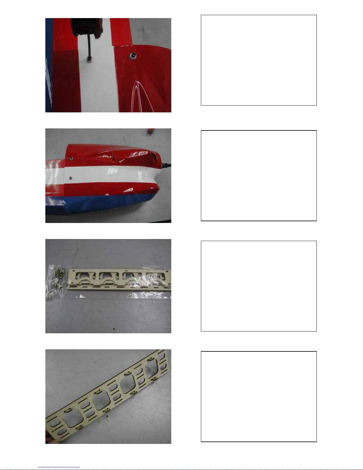
Install four blind nuts from back side o
f
fire wall.
as show.
Follow the mark to drill eight
3mm hole.

Install the motor as show.
Install the motor mount as show.
Find cowl fix parts.
Install the cowl and and made sure the
drive hub have distance for cowl end
3mm.

If you find the motor mount will touch
the cowl.
Please cut the cooling vent shorter as
shorter as show.
After you trim fit the motor mount with
the cowl drill two 4mm hole at each
side of cowl and fus. Side .
Then install two blind nut at each Fus.
Side.
Install two “O” ring at each side of
cowl as show.
Fix the cowl with four M3 screw.
Find the battery tay as show.
Assemble FRP. Teeth as show.
N
otice: the teeth direction was forward.
Assemble battery tray as show.
Install the battery in side the battery
tray, if the are differ size you can
choice not use the center plywood.
Fix the battery with wire tight.
Trim off the film at slot area.
Install the battery under pipe tunnel
then follow the hole at end of battery
tray to drill a 3mm hole.
Follow the hole to install a blind nut for
battery tray fix.
Lockup the battery tray with a M3
screw.
If you choice use Glow power. Follow
engine mount template to drill the hole
the engine or motor that you use on the
fire wall.
N
otice: “M” mark was for YS140-160
or OS.160 .
“E” mark was for “Hacker C50 XL
motor.
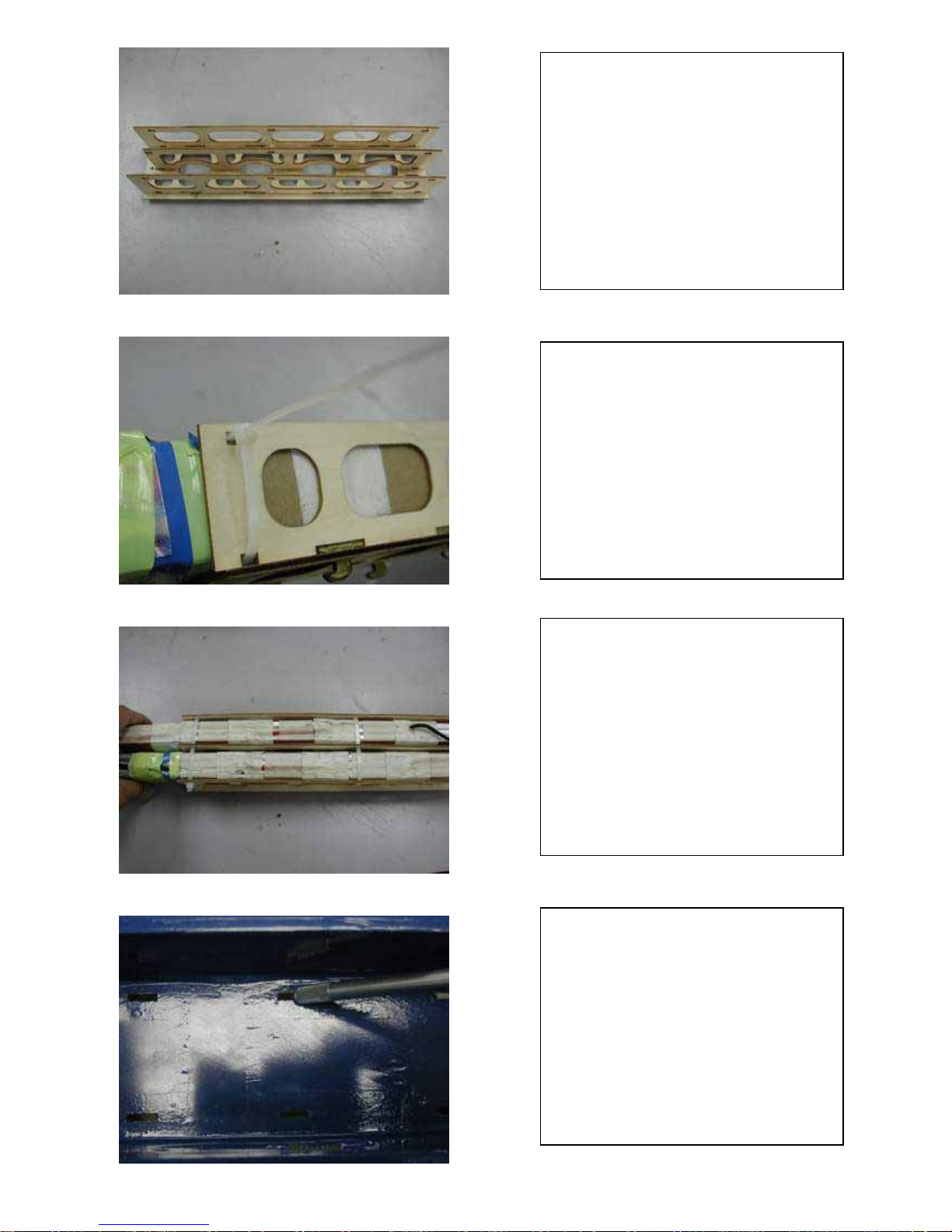
We recommend you if you use high
vibration engine such “YS” 4T engine ,
you should use a good soft mount,
unless will cause airplane damage.
The motor drive hub distance from
fire wall 168 mm
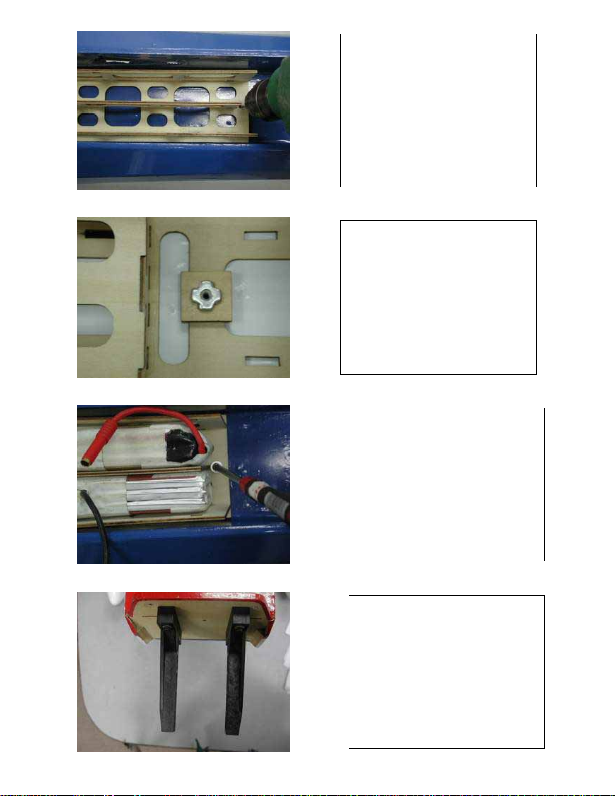
Find the fuel tank as show.
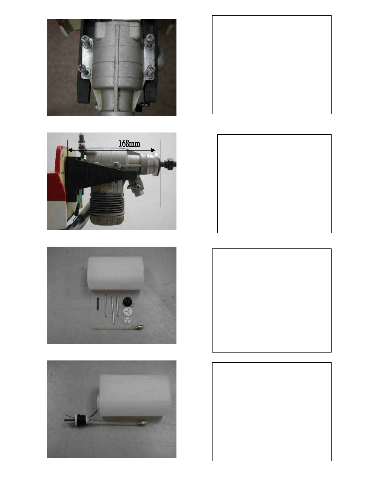
Assembling the Fuel line in fuel tank as
the show.
If use use glow engine with a pump
or Gas engine you can use the fuel
tank mount made fuel tank on CG.
Point. If your engine with no pump,
you must install engine near by
engine or add a fuel pump.
If you use E-power, you don’t need to
install this fuel tank mount at all.
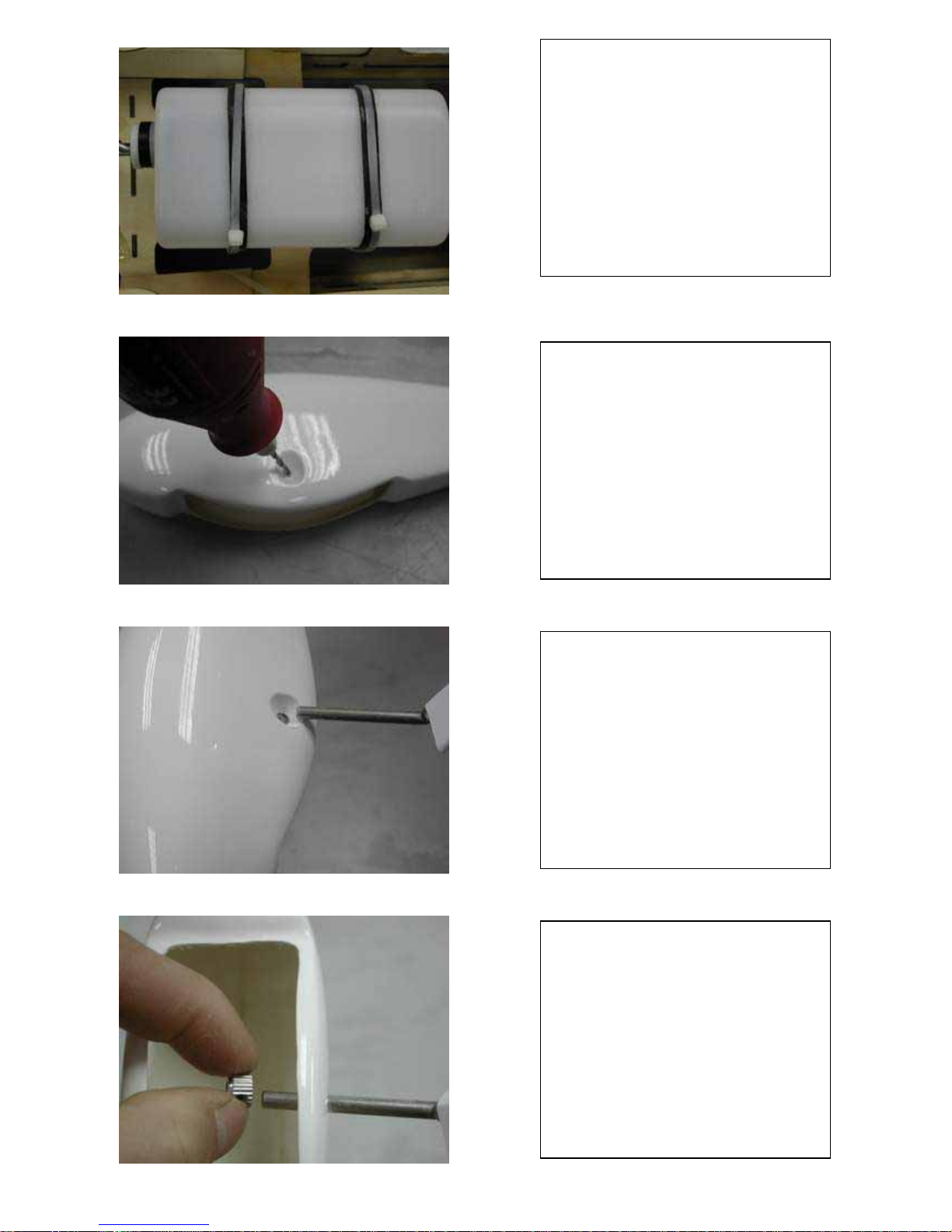
Drill a 40mm hole at each wheel
p
ants.
Inset the wheel Axle inside the wheel
p
ants.
Install the wheel shopper at wheel
axle.
Install the wheel shopper at wheel
axle between wheel and wheel pants.
Install the wheel second shopper at
wheel axle to hole wheel.
Then fix shopper with set screw.
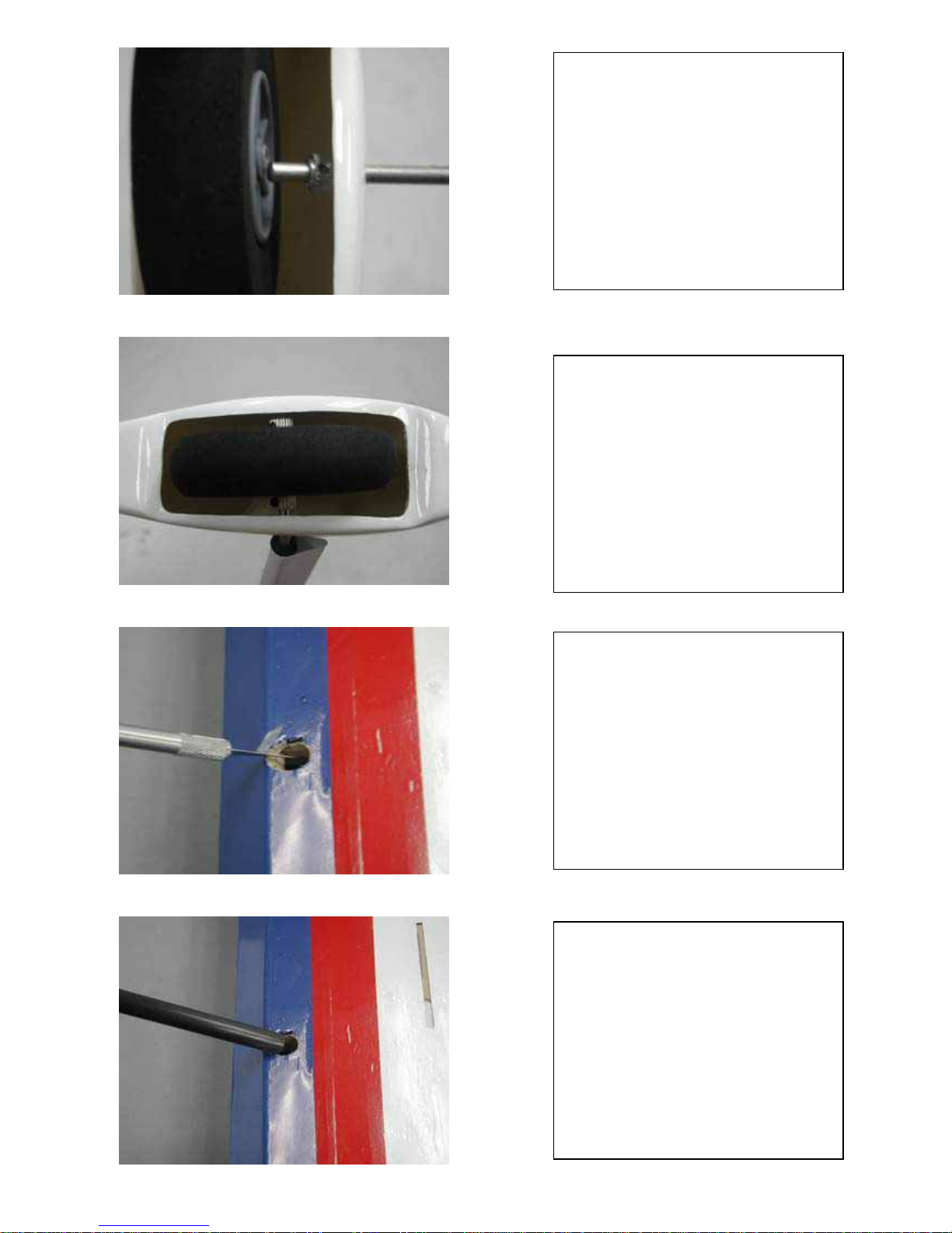
Trim off the cover film as show.
Install the landing gear sleeve inside
fus. If there have some thing made
you can not inset the sleeve, please
use sanding paper or file made that
sleeve more easy to inset to Fus.
But don’t made it too loosing.
Inset landing inside the sleeve as
show.
Install the landing gear in sleeve then
use a M3 screw and look nut fix it
together.
And use Epoxy to glue it with fus.
Together.
Important notice: before you glue
landing you must made sure a pair
wheel must straight with center of fus
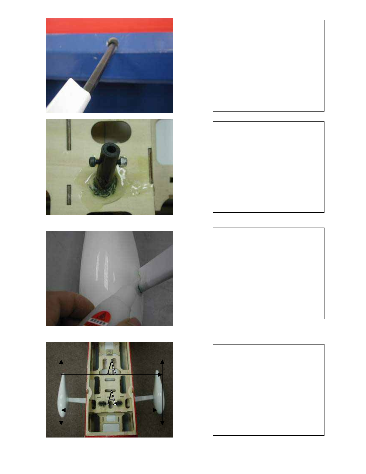
Glue the wheel pants and landing
gear with Epoxy.
Before you glue the landing gear ,
p
lease check and made sure the main
wheel are straight with center line of
Fus.

If you choice a tuned pipe for your
Exhaust .
Please follow your tuned pipe.manual
to install the tuned or you can follow
here. Drill two 3mm hole at top of
p
ipe tunnel as show.
Then use two M3 screw to fix the
p
ipe as show.
The pipe after install as show.
***Check the all Alignment as the show before you install wing and tail plane.****

Cod
e
NO. Description DIM. QUT'Y
A ME030 TAIL LANDING GEAR Φ6X50 1PC
PI012
WH014 TAIL WHELL Φ25X 13 1pc
ME001 COLLAR M2 2pcs
ME029 SET SCREW Ø3x3 2pcs
WINCH KEY for SET SCREW Φ1.5X30 1PC
TP. SCREW Ø2X12 2pcs
TP. SCREW Ø2X12 2pcs
B PI003 PIN HINGES FOR RUDDER Ø2.5X48 4pcs
RO005 RUDDER CONTROL HORN 2.5X28.6 2pcs
HORN SCREW FOR RUDDER 3X30 2pcs
HORN NUTS FOR RUDDER M3 2pcs
LK03S
BALL LINK END 4set
ME015 BALL LINK CONNENTOR Ø2X20 4PCS
ME033 RUDDER CONTROL WIRE 0.6X1150 2PCS
SINK TUBE FOR CONTROL WIRE 3x30 4PCS
ME023 RUDDER CONTROL WIRE PIPE 1.8X10 4PCS
RO002 RUDDER SERVO EXTEND HORN 1PCS
RUDDER SERVO EXTEND HORN SC
R
Ø2X6 2PCS
SERVO EXTEND HORN NUTS M2 2pcs
C PI003 PIN HINGES FOR ELEVATOR Φ2.5X48 8PCS
RO006 ELEVATOR CONTROL HORN 20X28.5 2pcs
TP. SCREW ELE. CONTROL HORN Φ2X15 6PCS
LK03S
BALL LINK END 4SET
ME013 BALL LINK CONNENTOR Φ2X20 2PCS
ME031 WIRE PUSH ROD Φ2X280 2PCS
CARBON PIPE FOR STAB. Ø12.7X316 1PC
CARBON ANTI ROLL PIN OF STAB. Ø6X80 2PCS
STAB. FIX SCREW Φ3X15 4PCS
STAB. FIX SCREW WASHER Φ3X10 4PCS
RO001 ELEVATOR SERVO EXTEND HORN 2PCS
BALL LINK SCREW Φ2x13 4PCS
BALL LINK NUTS M2 4PCS
D1 PI003 PIN HINGES FOR AILERON Φ2.5X48 12PCS
RO006 AILERON CONTROL HORN 20X28.5 2PCS
AILERON CONTROL HORN SCREW Ø2X15 6PCS
LK03S
BALL LINK END 4SET
p.01
Parts list E-EVOLUTION
第 1 页

Cod
e
NO. Description DIM. QUT'Y
ME031 WIRE PUSH ROD Φ2X280 2PCS
ME013 BALL LINK CONNENTOR Φ2X20 2PCS
RO001 AILERON SERVO EXTEND HORN 2PCS
SCREW FOR SERVO EXTEND HOR
N
Ø2X6 4PCS
NUTS M2 4PCS
D2 CARBON WING JOIN Ø25.4X497 1PC
FRP. WING LOOK 4PCS
WOOD SUPPORT FOR WING LOOK 4PCS
WING BOLT Φ3X15 4PCS
WASHER FOR WING BOLT Φ3X8 4PCS
"O" RING FOR WING BOLT Φ3X6 4PCS
BLIND NUTS FOR WING BOLT M3 4PCS
PLY SUPPORT FOR WING TUBE 25.4X35 2PCS
FRP. WING TUBE SLEEVE 25.4x130 1PC
E CANOPY LOCK WIRE Ø1.8x155 1PC
CANOPY LOCK WIRE END COVER 2PCS
F HX.SCREW FOR COWL Ø3X10 4PCS
BLIND NUTS FOR COWL SCREW M3 4PCS
WASHER FOR SCREW FOR COWL Ø3X8 4PCS
"O" RING FOR COWL SCREW 4PCS
G GA005 FUEL TANK 448CC 1SET
FUEL TANK TIGHTED TAPE 5x350mm 3PCS
H BOLTS FOR LANDING GEA
R
Φ3x15 2PCS
LOCK NUT FOR LANDING GEA
R
M3 2PCS
A119-LG CARBON LANDING GEAR 1SET
ME006 WHEEL COLLAR M4 4PCS
ME029 SET SCREW WHEEL COLLAR Ø3x3 4PCS
WH001 MAIN WHEELS Φ4X75 2PCS
A119-WP
WHEEL PANTS 1PAIR
J1 KI001 ENGINE MOUNTS 68X105 1SET
BLIND NUTS FOR ENGINE MOU M4 4PCS
J2 A119-WS MOTOR MOUNT 1PC
MOTOR MOUNT TEMPLATE 1PC
HX.SCREW FOR MOTOR MOUNT M3X20 4PCS
WASHER MOTOR MOUNT BOTLS M3X8 4PCS
BATTERY TRAY LOCK THEETH 8PCS
A119-BS BATTERY TRAY 1 SET
SCREW FOR BATTERY TRAY M3X15 1PC
WASHER FOR BATTERY TRAY SCR
E
M3X8 1个
BLIND NUT FOR BATTERY TRAY 1个
PLY SUPPORT FOR BLIND NUT 18x25x3mm 1PC
p.02
Parts list E-EVOLUTION
第 2 页

SPECIFICATION
CODE A119 ITEM E-EVOLUTION
WING SPAN
WING AERA
TOTAL LENGTH
ROOT AIRFOIL
TIP AIRFOIL
1950.6mm
62.4dm
1980mm
11.80%
11.80%
2
MOTOR Haker C50 XLMotor
RTF. WEIGHT 4.3-5kg
Recommented Battery Lipo5000MA 10S 37V 1.3 KG
WING LOADING
CENTER OF GRAVITY 200mm from LE
WING INCIDENCE 0 °
WING DIHEDRAL
1°
STAB. INCIDENCE 0 °
RIGHT THRUST 2-3 °
DOWN THRUST 0 °
 Loading...