

Page 1
Revision 25 of DOCU225
Revised May 1, 2019
Quick Links
Overview 6
Understanding Pason WITS 7
Pason WITS User Guide
Connecting Hardware for WITS Communication 9
Setting Up WITS in the EDR 14
Using the WITS Monitor 39
About WITS Port Pin-Outs 42
Page 2

Revised May 1, 2019
Revision 25 of DOCU225, © Copyright
Page 2 of 44
This document contains proprietary information and is not intended for public distribution. Pason
Systems and all other trademarks and trade names used in this document, unless otherwise
specified, are the property of Pason Systems Corp.
No part of this document may be reproduced by any means, nor transmitted, nor translated, nor
translated into computer language, in whole or in part, without written permission from Pason
Systems Corp.
As updates and modifications occur, a new document will be made available as appropriate.
The revision date on the title page determines the most current version of the document.
Documents with the latest date replace any and all previous versions of the same document.
The most current is definitive in case of contradictions, errors, omissions, or misstatements.
While all reasonable care has been taken in the preparation of this document, no liability is
accepted by the author(s) for any errors, omissions or misstatements it may contain, or for any
loss or damage, howsoever occasioned, to any person relying on any statement or omission in
this document.
Copyright © 2018 Pason Systems Corp.
Any questions regarding this document or others should be forwarded to the following:
Pason Systems Corp.
6130 – 3rd Street S.E.
Calgary, Alberta T2H 1K4
Canada
Phone: 1-403-301-3400
Fax: 1-403-301-3499
Email: info@pason.com
Website: www.pason.com
For 24-hour support, phone the Technical Support Centre toll free: 1-877-255-3158
Page 3

Revised May 1, 2019
Revision 25 of DOCU225, © Copyright
Page 3 of 44
Table of Contents
1 Overview ............................................................................................ 6
2 Understanding Pason WITS .............................................................. 7
2.1 Setting Up ...................................................................................................... 7
2.2 Duplex Communication .................................................................................. 7
2.3 Handshaking .................................................................................................. 7
2.4 About WITS Levels and Packets .................................................................... 7
2.5 What is the 1984PASON/EDR Header .......................................................... 7
3 Connecting Hardware for WITS Communication ............................ 9
3.1 Connection Instructions for Third-Party Users ............................................... 9
Connecting a WITS Device via a Pason Workstation ............................................... 9
Connecting a WITS Device via the Toolpush Connection Box or Network Panel
using a COMM022 ..................................................................................................10
Connecting a WITS Device via a Pason DHC, SideKick, or UJB ............................12
3.2 Testing WITS Connections .......................................................................... 13
4 Setting Up WITS in the EDR ............................................................ 14
4.1 Set up on UJB .............................................................................................. 14
4.2 About Handshaking ...................................................................................... 14
Establishing and Maintaining WITS Communication ...............................................14
4.3 Setting up the EDR Comm Port ................................................................... 15
Setting up an EDR Comm Port for WITS Connections via a DHC, Workstation,
SideKick, or UJB.....................................................................................................15
Setting up the EDR Comm Port for WITS Connections via Toolpush Connection
Box or Network Panel .............................................................................................15
Determining the Assigned Comm Port for WITS Connections via Toolpush
Connection Box or Network Panel ..........................................................................16
Setting the Assigned Comm Port’s Transmission Speed for WITS Connections
via Toolpush Connection Box or Network Panel .....................................................16
4.4 Setting the Send/Receive Mode ................................................................... 17
Send/Receive Options for WITS Connections to a DHC, Workstation, SideKick,
or UJB ....................................................................................................................17
Send/Receive Options for WITS Connections via Toolpush Connection Box or
Network Panel ........................................................................................................17
Page 4

Revised May 1, 2019
Revision 25 of DOCU225, © Copyright
Page 4 of 44
4.5 Selecting WITS Codes ................................................................................. 19
Selecting Pason Traces for the EDR to Send .........................................................23
4.6 Configuring Custom WITS in the EDR ......................................................... 24
Setting up Custom WITS Codes .............................................................................24
Selecting Custom WITS Codes to Send .................................................................27
Receiving a Custom WITS Code and Sending it as a Different Custom Code ........27
4.7 Setting Up WITS Codes for Custom Sensors .............................................. 29
4.8 Sending WITS 01 Codes to the EDR ........................................................... 30
4.9 Sending Gamma and Gamma Lag Calc ...................................................... 30
4.10 Importing and Exporting Your WITS Settings ............................................... 31
4.11 Default Pason WITS Codes ......................................................................... 32
4.12 Typical WITS Packets sent to Pason ........................................................... 36
4.13 Sample Half WITS Data Sent by Pason ....................................................... 37
4.14 Sample Full WITS Data Sent by Pason ....................................................... 37
4.15 Using the WITS Monitor ............................................................................... 39
5 About WITS Port Pin-Outs .............................................................. 42
5.1 RS232 Port Pin-Outs .................................................................................... 42
COMM022 RS232 Pin-Outs ...................................................................................42
COMM018 RS232 Pin-Outs ...................................................................................43
5.2 RS422 Port Pin-Outs .................................................................................... 43
Page 5

Revised May 1, 2019
Revision 25 of DOCU225, © Copyright
Page 5 of 44
Table of Figures
Figure 1: Connecting a WITS device to a Pason Workstation .................................................................... 10
Figure 2: Connecting a WITS device to a toolpush connection box ........................................................... 10
Figure 3: Connecting a WITS device to a network panel ............................................................................ 11
Figure 4: COMM022 comm box and components ...................................................................................... 11
Figure 5: COMM087 comm box and components ...................................................................................... 12
Figure 6: Connecting a WITS device to a DHC, SideKick, or UJB ............................................................. 13
Figure 7: Recommended WITS handshaking packet ................................................................................. 15
Figure 8: Comm port with a WITS connection ............................................................................................ 16
Figure 9: Comm Port Setup screen ............................................................................................................ 18
Figure 10: WITS Comm Options screen ..................................................................................................... 19
Figure 11: WITS setup screen .................................................................................................................... 23
Figure 12: Highlighted custom WITS row ................................................................................................... 25
Figure 13: Changing a custom WITS code used for sending ..................................................................... 28
Figure 14: WITS in All tab ........................................................................................................................... 30
Figure 15: WITS Monitor screen ................................................................................................................. 40
Figure 16: WITS monitor raw data (left) versus interpreted data (right) ..................................................... 41
Figure 17: COMM022 RS232 pin-outs ........................................................................................................ 42
Figure 18: COMM018 RS232 pin-outs ........................................................................................................ 43
Figure 19: RS422 ports pin-outs ................................................................................................................. 44
Page 6

Revised May 1, 2019
Revision 25 of DOCU225, © Copyright
Page 6 of 44
1 Overview
This document describes how to set up and use WITS communication with EDR version
3.12.0 or later.
The Wellsite Information Transfer Specification (WITS) is a communication protocol
used to transfer wellsite data between computer systems. The WITS specification is an
industry-wide standard used by companies involved in petroleum exploration and
production.
The Pason Electronic Drilling Recorder (EDR) can use WITS to communicate with
another service company’s equipment. Service companies, referred to as a third parties
in this document, may only need to receive specific data, or send specific data to the
EDR, but in most cases, they want to both send and receive data. Using WITS is a
proven and reliable way to accomplish these goals.
Page 7

Revised May 1, 2019
Revision 25 of DOCU225, © Copyright
Page 7 of 44
2 Understanding Pason WITS
2.1 Setting Up
Setting up and using WITS with a Pason EDR involves these general steps:
1. Physically connecting third-party hardware to the Pason system
2. Establishing WITS communication between the third-party device and the EDR,
often called handshaking
3. Setting up the EDR for WITS communication
4. Setting up the third-party device for WITS communication
The second step, establishing WITS communication, is typically where most problems
occur. To avoid WITS-related problems, consider the information below about WITS in a
Pason system.
2.2 Duplex Communication
Pason recommends full duplex communication when using WITS. With full duplex
communication, data can travel in two directions simultaneously. This is different than
half duplex communication, which allows data to travel in one direction at a time, like
voices on walkie-talkie radios.
2.3 Handshaking
Establishing and maintaining WITS communication between connected WITS devices
and the EDR requires a handshaking procedure. For details about how to complete the
handshaking process, see About Handshaking on page 14.
2.4 About WITS Levels and Packets
The Pason system uses WITS Level 0 for serial communications. In Send and Receive
mode, the EDR transmits a number of WITS Level 0 packets (1 packet in Half WITS
mode, approximately 8 packets in Full WITS mode) each time it receives a valid WITS
Level 0 packet.
2.5 What is the 1984PASON/EDR Header
Every WITS record the Pason EDR sends includes a 1984PASON/EDR header. This
does not exactly meet the WITS specification, which specifies that items from different
Page 8

Revised May 1, 2019
Revision 25 of DOCU225, © Copyright
Page 8 of 44
records should be in different packets. However, this item is required due to the half
duplex nature of our communication cables. The EDR uses this header to distinguish
between sent data and received data.
If a WITS device requires the removal of the 1984PASON/EDR header, ensure that the
device is connected to the EDR via a COMM022, and that its EDR comm port is set to
Send Only. Refer to Setting the Send/Receive Mode on page 17 for step-by-step
instructions.
Page 9

Revised May 1, 2019
Revision 25 of DOCU225, © Copyright
Page 9 of 44
3 Connecting Hardware for WITS Communication
WITS communication requires a physical connection between Pason and third-party
systems. This section includes information about how to complete the required hardware
connections.
3.1 Connection Instructions for Third-Party Users
Third parties can connect their systems to Pason’s using one of these three methods:
• Connect to a Pason Workstation computer (TPC and VSP systems).
• Connect to the toolpush connection box (TPC systems) or network panel
(VSP systems).
• Connect to a Pason Doghouse Computer (DHC), SideKick, or Universal
Junction Box (UJB) (TPC and VSP systems).
Important:
Pason only supports the three above methods to connect WITS devices to our system.
Specifically, note that the RS-232 ports on trailer access points (TAPs) do not support WITS
connections. WITS connections to TAPs haven’t been fully tested and their reliability is unknown.
Connecting a WITS device to a DHC or SideKick can in some cases adversely affect wireless
communications between the DHC and the network.
All of the parts and cables described in the following connection procedures are
available for purchase from your Pason representative.
Once third parties connect their hardware, Pason recommends that a Pason field
technician inspect the connections and complete the initial WITS set up in the EDR.
Connecting a WITS Device via a Pason Workstation
Connecting a WITS device via a Pason Workstation is the most common connection
method. Follow these steps to connect a WITS device to the EDR via a Pason
Workstation:
1. Ensure that the Pason Workstation is powered on.
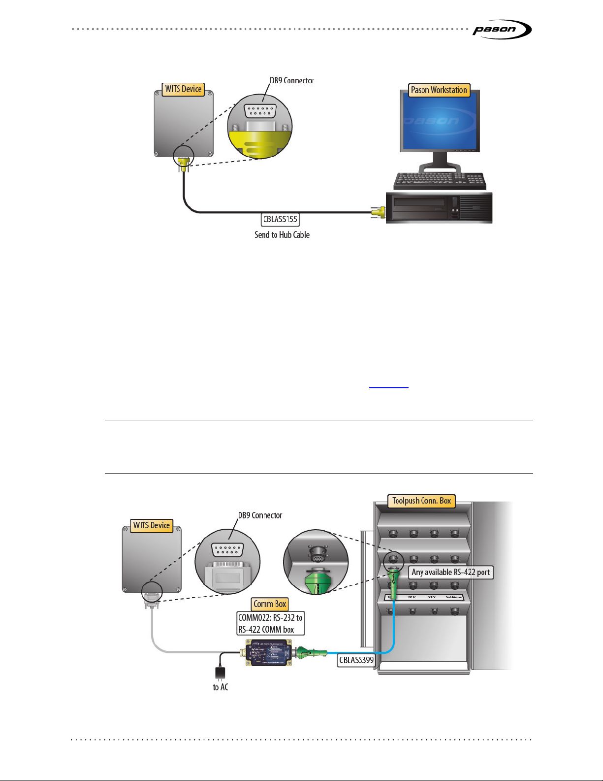
2. Use a Pason Send to Hub cable (CBLASS155), or a generic DB9 9-pin serial null
modem cable, to connect the WITS device to comm port 1 on the Pason
Workstation as shown in Figure 1.
Page 10
Revised May 1, 2019
Revision 25 of DOCU225, © Copyright
Page 10 of 44
Figure 1: Connecting a WITS device to a Pason Workstation
Connecting a WITS Device via the Toolpush Connection Box or Network Panel using a COMM022
This method involves using an RS-232 to RS-422 communication box (COMM022) to
connect the WITS device. Toolpush connection boxes and network panels are typically
located on an outside wall of the rig manager’s trailer. Look over the illustrations below
to see the connections to the different types of panels. Figure 4 on page 11 shows a
COMM022 in more detail.
Note:
Pason COMM022 communication (comm) boxes ship with full duplex communication enabled.
COMM022 comm boxes have a jumper that enables you to choose half or full duplex, but Pason
recommends using the default full duplex setting.
Figure 2: Connecting a WITS device to a toolpush connection box
Page 11
Revised May 1, 2019
Revision 25 of DOCU225, © Copyright
Page 11 of 44
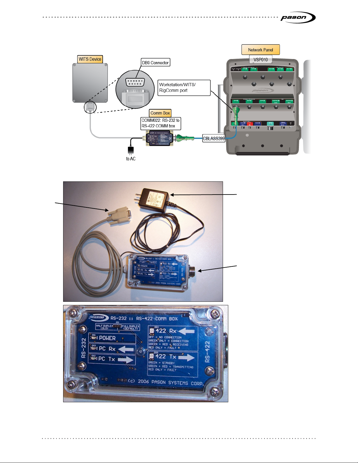
Figure 3: Connecting a WITS device to a network panel
DB-9
AC plug
Military 10 pin connector
RS-422
RigComm
Figure 4: COMM022 comm box and components
Page 12
Revised May 1, 2019
Revision 25 of DOCU225, © Copyright
Page 12 of 44
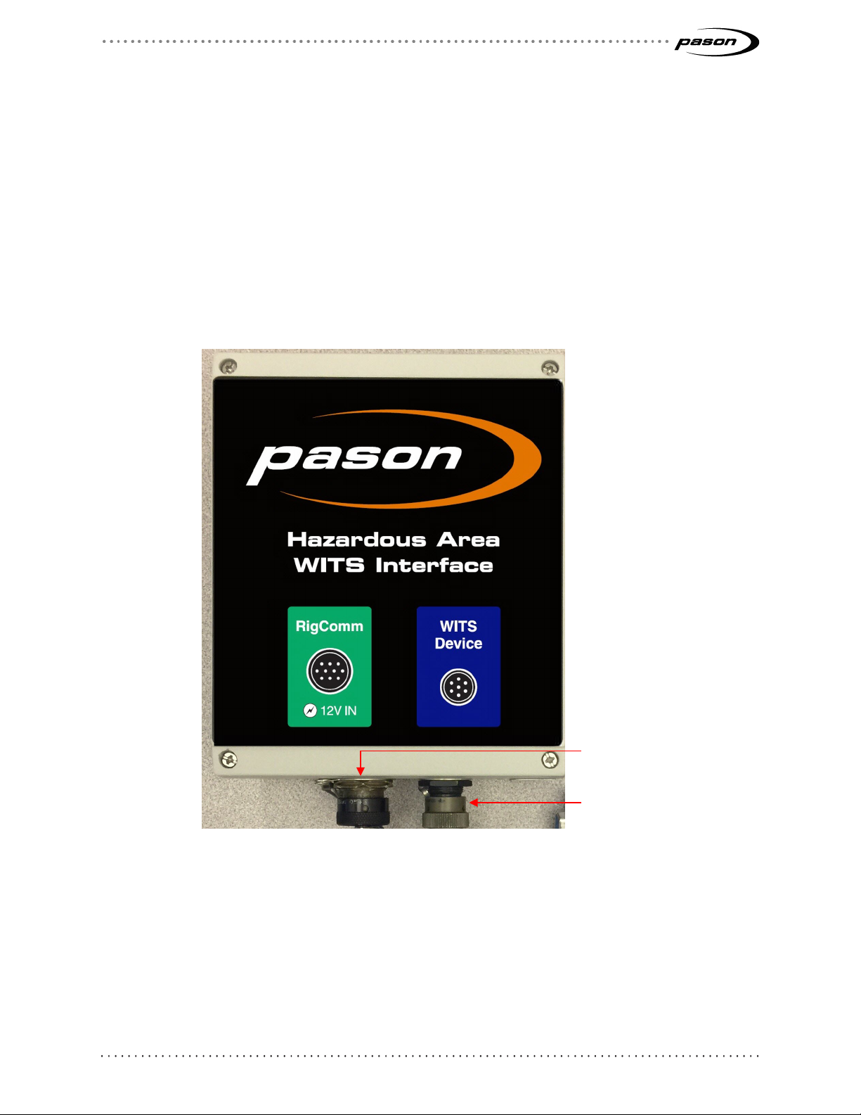
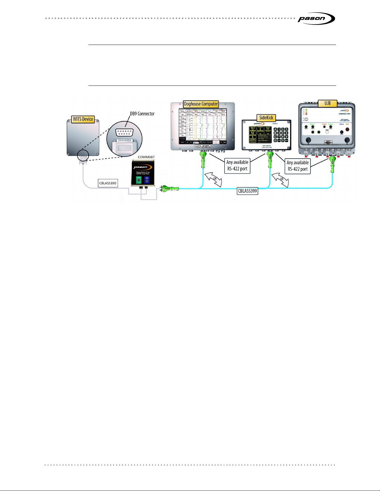
Connecting a WITS Device via a Pason DHC, SideKick, or UJB
WITS Device port
When connecting a WITS device in potentially hazardous areas, use the Hazardous
Area WITS Interface Assembly (COMM087) instead of COMM022. COMM087 is
certified for Class 1 Division 2 areas. Follow these steps to connect COMM087 to the
EDR via a Pason DHC, SideKick, or UJB:
1. Ensure that the DHC, SideKick, or UJB is powered on.
2. Secure the WITS to RS232, 6 ft. cable (CBLASS390) to the WITS Device port on
the Hazardous Area WITS Interface Assembly (COMM087). Secure the female
DB-9 end to the WITS device.
RigComm port (to DHC,
Sidekick, UJB)
Figure 5: COMM087 comm box and components
3. Connect a RigComm RS-422 cable to the RigComm port on COMM087. Connect
the other end to any available powered RS-422 port on the DHC, SideKick, or
UJB, as shown in Figure 6. If connecting to a SideKick, use the 2.5ft Power
Rignet Y-Adapter cable (CBLASS360) to create the powered port.
Page 13
Revised May 1, 2019
Revision 25 of DOCU225, © Copyright
Page 13 of 44
Important:
If connecting to a SideKick, ensure that the port you’re using is set to Auto (Port Info >
Port Setup from the SideKick’s main screen). If connecting to a UJB, ensure the port is
set to WITS (Setup Ports > Change to WITS from the UJB local interface). This requires
UJB firware version 11 or higher.
Figure 6: Connecting a WITS device to a DHC, SideKick, or UJB
3.2 Testing WITS Connections
If you are having problems with WITS communication, a Pason field technician can test
WITS connections using the proprietary Pason WITS RSVP application. For help testing
your WITS connections, contact Pason Technical Support at 1-877-255-3158.
Page 14

Revised May 1, 2019
Revision 25 of DOCU225, © Copyright
Page 14 of 44
4 Setting Up WITS in the EDR
After connecting the hardware, you need to use the EDR to set up WITS communication.
Set up procedures vary depending on whether you connected the WITS device to the
EDR via a comm box or via a Workstation, DHC, or SideKick. The following sections
describe the required procedures.
4.1 Set up on UJB
If connecting to a UJB, ensure the port is set to WITS. This requires UJB firmware
version 11 or higher. Select Setup Ports > Change to WITS from the UJB local
interface. Then select either WITS 9600 or WITS 19200.
4.2 About Handshaking
Setting up and maintaining WITS communication between a WITS device and the EDR
requires the use of a handshake. The handshake is important because it prompts the
EDR to recognize that a WITS device has been connected to the system, and is
necessary for the EDR to keep WITS communication active. If you connected the WITS
device via a toolpush connection box or a network panel, handshaking also prompts the
EDR to display a WITS protocol in the Comm Port Setup screen, so handshaking is
useful for determining which ports are connected to WITS devices.
Important:
Failure to continuously send at least one packet to the EDR every 30 seconds causes the EDR’s
communication engine to time out, stopping WITS communication. This is a major cause of WITS
communication problems.
Establishing and Maintaining WITS Communication
To establish and maintain WITS communication with the EDR, the third-party WITS
device must send at least one WITS packet to the EDR continuously every 30 seconds,
even if the third-party has no other need to send WITS packets. The only exception to
this requirement is when the WITS device is connected via a toolpush connection box or
a network panel, and the EDR comm port is set to Send Only. This requirement can be
met in one of the following two ways:
• The third-party WITS device continuously sends at least one WITS packet to the
EDR every 30 seconds as part of the desired operation, or
Page 15

Revised May 1, 2019
Revision 25 of DOCU225, © Copyright
Page 15 of 44
• The third-party WITS device is set up to continuously send a handshaking packet
to the EDR every 30 seconds. Pason recommends continuously sending a TVD
WITS packet configured as shown in Figure 7. The EDR is coded to recognize
and use this specific packet for maintaining WITS communication, but can also
receive TVD WITS packets with actual values from other WITS devices at the
same time. The EDR is capable of receiving this handshaking packet from
multiple WITS devices simultaneously.
Be sure to include all of the carriage return and line feed characters shown
below.
&&<cr><lf>
0111-9999<cr><lf>
!!<cr><lf>
Figure 7: Recommended WITS handshaking packet
4.3 Setting up the EDR Comm Port
Setting up an EDR Comm Port for WITS Connections via a DHC, Workstation, SideKick, or UJB
If you connected the WITS device to the EDR via a DHC, Workstation, SideKick, or UJB,
the device doesn’t appear in the EDR Comm Port list. In these cases, you do not need to
set up a comm port. To determine if WITS is working in these setups, check the WITS
monitor, check the EDR for WITS traces sent by the third-party device, or check the
third-party device for WITS values sent by the EDR.
Important:
As a best practice, Pason recommends connecting WITS devices before setting up comm ports
and configuring WITS in the EDR.
Setting up the EDR Comm Port for WITS Connections via Toolpush Connection Box or Network Panel
If you connected the WITS device to one of these panels with a COMM022, the EDR
assigns the device a comm port. The EDR also enables you to select a transmission
speed (in bits per second) for connected comm ports, but Pason strongly recommends
using the default Auto setting.
To set up the EDR comm port, you need to determine the assigned comm port and then
configure it.
Page 16

Revised May 1, 2019
Revision 25 of DOCU225, © Copyright
Page 16 of 44
Determining the Assigned Comm Port for WITS Connections via Toolpush Connection Box or Network Panel
The EDR uses several comm ports for communicating, so you need to determine which
port the EDR uses for WITS.
Follow the steps below to find the assigned port if you connected the WITS device to the
TPC via a COMM022:
1. Connect the WITS device and have it send any WITS value to the EDR.
2. From the EDR main screen click Menu > Setup > Comm Ports. The Comm Port
Setup screen opens.
3. Use the navigation buttons to scroll through the comm ports list until you see a
comm port showing one of the following under New Protocol: WITS 9600 (8,N,1),
WITS 115200 (8,N,1), WITS 230400 (8,N,1), WITS 460800 (8,N,1), or WITS
921600 (8,N,1). Comm ports connected to WITS devices display one of these
WITS protocols.
Setting the Assigned Comm Port’s Transmission Speed for WITS Connections via Toolpush Connection Box or Network Panel
Every EDR comm port has a protocol that defines transmission speed (in bits per
second) and serial port parameters. All EDR WITS protocols use serial port parameters
of 8,N,1, but each protocol includes a unique transmission speed. For example, the
protocol labelled “WITS 9600 (8,N,1),” uses a transmission speed of 9600 bits per
Figure 8: Comm port with a WITS connection
Page 17

Revised May 1, 2019
Revision 25 of DOCU225, © Copyright
Page 17 of 44
second. To change the transmission speed, select a protocol that uses the desired
speed.
Important:
High speed settings are a major cause of WITS transmission errors. For WITS, Pason
recommends using a speed of 9600 bits per second. If you experience errors when using WITS,
try decreasing the transmission speed.
Follow the steps below to configure the assigned WITS comm port protocol if you
connected the WITS device to the TPC via a COMM022:
1. From the EDR main screen click Menu > Setup > Comm Ports. The Comm Port
Setup screen opens.
2. Select the assigned comm port and use the Toggle Next button to scroll through
the list of available protocols until the desired protocol is listed under Configured
Protocol.
3. Click Exit to save the settings.
4.4 Setting the Send/Receive Mode
How you connect the WITS device to the Pason system determines which Send/Receive
options are available.
Send/Receive Options for WITS Connections to a DHC, Workstation, SideKick, or UJB
DHC, Workstation, SideKick, and UJB hardware is hard-coded to send and receive, so
you cannot use send only mode or receive only mode when you connect to a WITS
device via these devices. With these setups, the handshaking procedure on page 14
instructs the EDR how to communicate with the WITS device.
Send/Receive Options for WITS Connections via Toolpush Connection Box or Network Panel
If you connected the WITS device to one of these panels with a COMM022, you can set
the EDR to send WITS data, to receive WITS data, or to send and receive WITS data.
Once you have connected to the TPC via a comm box and have established a
handshake as described in Establishing and Maintaining WITS Communication on page
14, follow the procedure below to set up whether the EDR sends, receives, or sends and
receives WITS data through the assigned comm port:
1. From the EDR main screen on the RMPC, click Menu > Setup > Comm Ports.
Page 18

Revised May 1, 2019
Revision 25 of DOCU225, © Copyright
Page 18 of 44
The Comm Port Setup screen opens.
Figure 9: Comm Port Setup screen
2. Select the assigned WITS comm port as described in Determining the Assigned
Comm Port on page 16.
3. Click either Toggle Next or Toggle Prev to turn off the Auto setting and toggle
through the additional protocols.
4. Click WITS Setup. The WITS Comm Options screen opens.
Page 19

Revised May 1, 2019
Revision 25 of DOCU225, © Copyright
Page 19 of 44
Click Change
off.
to turn the
header on or
5. In the WITS Mode box, click the Change button to toggle to the mode you want
to use (Send and Receive, Send Only, or Receive Only). If you select Send Only
mode, the EDR displays a Use 1984 Header box that enables you to add or
remove Pason’s 1984PASON/EDR header (refer to What is the
1984PASON/EDR Header on page 7)
Figure 10: WITS Comm Options screen
6. When you are finished, click OK. The EDR returns to the Comm Port Setup
screen.
7. Click Exit to return to the EDR main screen.
4.5 Selecting WITS Codes
There are several ways to specify which WITS codes the EDR sends, as described
below, but the EDR is hard-coded to receive specific codes. The EDR can receive WITS
record 01, 02, 07, 08, 09, 11, 12, 17, 18, and 63 packets, plus custom WITS codes (see
the full table of valid WITS codes in Default Pason WITS Codes on page 32). If you need
the EDR to receive a code not listed in the table, you need to set up a custom WITS
code as described in Configuring Custom WITS in the EDR on page 24.
Depending on the type of workstation you are logged on to, the WITS setup screen in
Figure 11 on page 23 includes the elements in the table below.
Page 20

Revised May 1, 2019
Revision 25 of DOCU225, © Copyright
Page 20 of 44
Element Function
WITS Out TPC Server
WITS In All On the RMPC, use this tab to set up incoming WITS codes for all
Pason computers connected to WITS devices.
WITS Out RMPC On the RMPC, use this tab to set up WITS codes being sent to
devices connected to the RMPC.
On the RMPC, use this tab to set up WITS codes being sent to
devices connected to the TPC server.
WITS Out DHC/SideKick On the RMPC, use this tab to set up WITS codes being sent to
devices connected to the DHC or SideKick.
WITS Out Operator On an Operator Workstation, use this tab to set up WITS codes
being sent to devices connected to the Operator Workstation. This
feature is only available on US Operator Workstations. To see this
tab, the operator must have WITS editing privileges for the well.
WITS Out Workstation On a Workstation, use this tab to set up WITS codes being sent to
devices connected to the Workstation.
WITS Monitor Diagnostic tool for troubleshooting.
Transmission and
Interval
These settings are used together to determine the period between
sent WITS codes. They apply to all the WITS codes in the group
you select. Use the Transmission drop-down list to select the type
of transmission the interval is based on. Depending on which
WITS record group you are in, you can choose Time Based, Depth
Based, or Request-Response.
Time Based means that the Pason computer you are configuring
sends the record group’s enabled WITS codes at the time interval
you select.
Depth Based means that the Pason computer you are configuring
sends the record group’s enabled WITS codes at the depth
interval you select.
Request-Response means that the Pason computer you are
configuring sends the record group’s enabled WITS codes only
when a response is requested by a third-party WITS device.
Use the Interval drop-down list to select a time- or depth-based
interval.
Page 21

Revised May 1, 2019
Revision 25 of DOCU225, © Copyright
Page 21 of 44
The transmission and interval settings you select are applied to all
the WITS codes in a record group.
Important:
For WITS devices connected to a toolpush connection box or
network panel, conflicts between transmission settings and the
EDR’s comm port settings can cause problems. For example, if
you select Request-Response, but the comm port is set to Send
Only, then the EDR will fail to receive the third party’s data, and it
will not respond.
Unit Use this drop-down to select the display units for the WITS value.
Data Summary Use this drop-down list to select how the EDR calculates the WITS
value.
Import and Export See Sending Gamma and Gamma Lag Calc
When sending Gamma (code 0824) and Gamma Lag
Calc (code 0821) data to the EDR, make sure you
meet these packet and frequency requirements:
• Send both codes in the same WITS
packet. Problems occur when Pason
receives one or the other, but not both.
• Send the packet at a minimum 0.2 m (1 ft)
interval.
A well-formed gamma packet looks like this:
&&
1984PASON/EDR
08211780.2
082463.8
!!
Importing and Exporting Your WITS Settings on page 30.
Factory Reset Clears all your selections and returns the settings to the defaults.
Table 1: WITS setup screen elements
In addition to choosing individual WITS codes, the EDR provides the option of using
preconfigured Full WITS or Half WITS settings to determine which WITS codes it sends.
Page 22

Revised May 1, 2019
Revision 25 of DOCU225, © Copyright
Page 22 of 44
These modes include pre-selected sets of WITS codes, described in Default Pason
WITS Codes on page 32.
Tip:
Use the search box on the WITS setup screen to quickly jump to a specific WITS code.
To select standard WITS codes for a Pason computer to send, follow this procedure:
1. From the EDR main screen, click Menu > Setup > WITS. The WITS setup
screen opens.
2. Click the tab of the Pason computer you want to send the WITS codes, and
ensure that the Standard button is selected.
3. To select a preconfigured setting, click Full WITS or Half WITS.
Or,
4. To select outgoing WITS codes individually, click on an unselected WITS code’s
Enable check box.
5. Select the Transmission type and Interval for the selected group of WITS
codes. The transmission type and interval apply to all WITS codes in the group.
6. Select the display Unit, and type of Data Summary from the drop-down lists.
See Table 1 above for more information about these selections.
7. If desired, you can click in a code’s row, and enter a new WITS code for that row.
Any standard WITS code that you have changed displays a Reset button. If you
enter a WITS code that is already in use, click the Reset button to change back
to the default Pason WITS code.
8. When you are finished, click Save > Exit to return to the Setup Menu. The Pason
computer starts sending the selected WITS codes.
Page 23

Revised May 1, 2019
Revision 25 of DOCU225, © Copyright
Page 23 of 44
To enable an
outgoing WITS
code, select its
check box.
Figure 11: WITS setup screen
Selecting Pason Traces for the EDR to Send
Starting in EDR version 14.12, the WITS setup screen includes a feature that enables
you to send Pason trace data using WITS. Use this feature to send Pason traces that
aren't included with the standard WITS codes.
To select Pason traces to send, follow these steps from the EDR main screen on the
RMPC:
1. Click Menu > Setup > WITS. The WITS setup screen opens.
2. Click the tab of the Pason computer you want to send the WITS codes (WITS
Out RMPC, WITS Out TPC Server, etc.).
3. Click the Pason EDR Traces button. The screen displays all available EDR
traces not currently included as a standard WITS code.
4. Check the Enable check box of the traces you want to send.
5. Select a transmission type. The transmission type applies to all the Pason traces
you've selected.
6. If you're using a time-based transmission type, choose a time interval. The time
interval applies to all the Pason traces you've selected.
Page 24

Revised May 1, 2019
Revision 25 of DOCU225, © Copyright
Page 24 of 44
7. For each of your selections, enter the following information:
• Code: Enter a WITS code for the trace by clicking under Code in the trace's
row. If the code you enter conflicts with a code already in use, the EDR
displays an error message in the Status Message box and doesn't allow you
to save the changes.
• Units: Click under Unit in the trace's row and choose the units from the drop-
down list. Note that these are display units only—the EDR doesn't perform
conversions based on the units you select.
• Data Summary: If you've chosen a depth or time-based transmission type,
use the Data Summary drop-down list to select how the EDR calculates the
WITS value.
8. When you are finished configuring, click Save > Exit to return to the Setup Menu.
4.6 Configuring Custom WITS in the EDR
If you need to send or receive data not listed in the table of Default Pason WITS Codes
on page 32, you must set up a custom WITS code. Once a custom WITS code is set up,
the EDR can receive it from any connected WITS device, but you need to follow the
steps in Selecting Custom WITS Codes to Send on page 27 to instruct a Pason
computer to send custom WITS codes.
Setting up Custom WITS Codes
To set up a custom WITS code, use the following procedure:
1. From the EDR main screen on the RMPC, click Menu > Setup > WITS. The
WITS setup screen opens.
2. On the WITS In All tab, click the Custom button. The Custom WITS setup screen
opens. This screen displays 50 editable custom WITS codes, names, units,
adjustable decimal spaces, and shelf lives.
Page 25

Revised May 1, 2019
Revision 25 of DOCU225, © Copyright
Page 25 of 44
Enter your
row.
codes, names,
and units by
clicking in any
Figure 12: Highlighted custom WITS row
3. Click in a code’s row. The EDR highlights the row.
4. Within the highlighted row, enter the following custom code information:
• Code
Enter a WITS code for the trace by clicking under Code in the highlighted
row, and entering a four digit WITS code. Ensure that this code is different
from the existing WITS codes. If the code you enter conflicts with a current
EDR WITS code, the EDR highlights your entry in red and does not allow you
to save your settings.
• Name
To enter a name for the custom WITS code, click under Name in the
highlighted row and enter a name.
• Unit
To select the display units, click under Unit in the highlighted row and enter
the name of the display units. Note that these are display units only—the
EDR does not perform conversions based on the units you enter.
• Decimals
To select the number of decimal places the EDR uses for the WITS value,
Page 26

Revised May 1, 2019
Revision 25 of DOCU225, © Copyright
Page 26 of 44
click the Decimals drop-down box in the highlighted row and select 0, 1, 2, or
3 decimal places.
• Shelf Life
To select the length of time the EDR displays the WITS data, click the Shelf
Life drop-down list and choose 5 Mins (minutes), 15 Mins, 1 Hour, 12
Hours, 1 Day, or Never Expires. Once the shelf life period is exceeded, the
EDR changes the value of the trace to null, represented by two dashes (– –).
Important:
Shelf life is an important selection for time sensitive data. The EDR displays the last
received WITS value until the sender transmits a new value, or until it reaches the
end of the shelf life period. WITS data with a long shelf life can be misleading if users
don’t know the data’s age.
5. To enable your custom code to be sent or received, click on the code’s Enable
check box.
6. Click Save > Exit to return to the Setup Menu.
When you are finished, click Save > Exit. The EDR can now receive the custom WITS
code. To send this code, follow the directions in Selecting Custom WITS Codes to Send
below.
You can return all custom WITS settings to default at any time by clicking the Factory
Reset button.
Page 27

Revised May 1, 2019
Revision 25 of DOCU225, © Copyright
Page 27 of 44
Selecting Custom WITS Codes to Send
After you have set up a custom WITS code, follow the steps below to instruct a Pason
computer to send the code.
1. From the EDR main screen on the RMPC, click Menu > Setup > WITS. The
WITS setup screen opens.
2. On the WITS out tab of the Pason computer you want to send the custom WITS
code, click the Custom button.
3. From the Transmission drop-down list, select the transmission type for the
custom WITS group.
4. Click the custom code’s Enable checkbox.
5. Click Save > Exit to return to the Setup Menu. The Pason computer starts
sending the custom WITS codes you selected.
Receiving a Custom WITS Code and Sending it as a Different Custom Code
The EDR supports receiving a custom WITS value using one custom code and then
sending it using a different custom code. Use this feature if a third party on the rig is
sending a WITS code to Pason that they can’t change, but that code is unusable by
another party who wants to receive it from Pason. For example, Acme Drive Consulting
could be sending top drive RPM to the Pason system as 4002, but General Directional
Associates needs to get top drive RPM from Pason as 0120.
If you need to do this, follow the steps in Selecting Custom WITS Codes to Send above,
but before you save:
1. Click in a code’s row and delete the WITS code listed. This deletion doesn’t
affect the incoming code—it only prepares you for the next step.
2. Enter the custom four digit WITS code you want to use to send the value. Use a
code that’s different from the existing WITS codes. If the code you enter conflicts
with a current EDR WITS code, the EDR highlights your entry in red and does
not allow you to save your settings.
The example below, on an Operator workstation, shows an incoming custom WITS code
of 4002 ready to be deleted and given a new code used for sending.
Page 28

Revised May 1, 2019
Revision 25 of DOCU225, © Copyright
Page 28 of 44
Figure 13: Changing a custom WITS code used for sending
Page 29

Revised May 1, 2019
Revision 25 of DOCU225, © Copyright
Page 29 of 44
4.7 Setting Up WITS Codes for Custom Sensors
The EDR enables you to physically connect and monitor up to 50 custom sensors. If you
enter a name for the custom sensor when you set it up in the EDR’s Custom Calibration
Menu, you can assign it a custom WITS code, which you can instruct a Pason computer
to send.
Follow these steps to set up a Pason computer to send a custom WITS code for a
connected custom sensor:
1. Ensure that the custom sensor is connected, and assigned a name in the EDR’s
Custom Calibration Menu.
2. From the EDR main screen on the RMPC, click Menu > Setup > WITS. The
WITS setup screen opens.
3. On the WITS out tab of the Pason computer you want to send the custom WITS
code, click the Custom button.
4. Scroll down to the Custom Analog Port section. You should see the name of the
custom sensor listed.
5. Click in the custom code’s row. The EDR highlights the row.
6. Click under Code in the highlighted row, and enter a four digit WITS code.
Ensure that the code is different from existing WITS codes. If the code you enter
conflicts with a current EDR WITS code, the EDR highlights your entry in red and
does not allow you to save your settings.
7. Select a transmission type from the Transmission drop-down list.
8. To enable the selected Pason computer to send your custom code, click on the
code’s Enable check box.
9. Click Save > Exit. The Pason computer starts sending the custom WITS codes
you selected.
Note:
If you do not see any custom sensors listed in the Custom Analog Port section, ensure
that you assigned your custom sensor a name in the EDR’s Custom Calibration Menu.
The EDR will not list any custom sensors in the Custom Analog Port section unless you
have assigned a name to at least one of them.
Page 30

Revised May 1, 2019
Revision 25 of DOCU225, © Copyright
Page 30 of 44
4.8 Sending WITS 01 Codes to the EDR
The EDR can receive the WITS 01 codes noted in the Default Pason WITS Codes table
on page 32, but it’s an advanced EDR feature that you need to use with caution.
Before you set up the EDR to receive WITS 01 codes, think about these important
points:
• Contact your Pason representative for assistance before you set this up. If
not properly configured, WITS 01 code data can cause the EDR to display
incorrect values and negatively impact other applications.
• You’ll find the WITS in All tab on the WITS setup screen in the EDR (Figure
14).
• The EDR receives diff. pressure on code 0150 (even though it sends diff.
pressure on code 0171).
• If you send diff. pressure to the EDR, you must also send standpipe pressure
(0121).
Figure 14: WITS in All tab
4.9 Sending Gamma and Gamma Lag Calc
When sending Gamma (code 0824) and Gamma Lag Calc (code 0821) data to the EDR,
make sure you meet these packet and frequency requirements:
Page 31

Revised May 1, 2019
Revision 25 of DOCU225, © Copyright
Page 31 of 44
• Send both codes in the same WITS packet. Problems occur when Pason
receives one or the other, but not both.
• Send the packet at a minimum 0.2 m (1 ft) interval.
A well-formed gamma packet looks like this:
&&
1984PASON/EDR
08211780.2
082463.8
!!
4.10 Importing and Exporting Your WITS Settings
The EDR enables you to import and export saved WITS settings, for sharing via email or
USB memory stick.
Follow these steps to export WITS settings:
1. Select the WITS out tab of the Pason computer whose settings you want to
export.
2. Click the Export button.
3. Select a save location from the Save In drop-down list.
4. Enter a name for the saved settings file. Note that the default file name includes
the name of the Pason computer the settings are currently applied to, which is
useful.
5. Leave the file type at the default of WITS Out Template Files.
6. Click Save.
Follow these steps to import WITS settings:
1. Select the WITS out tab of the Pason computer you want to apply the imported
settings to.
2. Click Import.
3. Navigate to and select the settings file you want to import. This file must have a
.wto file extension.
4. Click Open. The EDR applies the saved WITS settings you selected, and
refreshes the WITS setup screen.
Note:
When you import WITS settings, the EDR overwrites your existing settings, including any
custom codes you have set up. Custom codes not included in the import file are deleted.
Page 32

Revised May 1, 2019
Revision 25 of DOCU225, © Copyright
Page 32 of 44
4.11 Default Pason WITS Codes
WITS
EDR can
EDR Sends in
Mode
EDR Sends in
Mode
Record 01: General Time Based
Well ID
0101
Date
0105
Bit Depth
0108 Y Y Y
Hole Depth
0110 Y Y Y
On Bottom ROP
0113 Y Y Y
Weight on Bit
0117 Y Y
Rotary Torque
0119 Y Y
Standpipe Pressure
0121 Y Y
Casing Pressure
0122 Y Y
Pump 3 strokes/min
0125 Y Y Y
PVT Total Mud Gain/Loss
0127 Y
Flow
0128 Y
Total Strokes P1+P2+P3+P4
0137 Y Y
3rd Party LagD
0139 Y Y
The following table lists the default Pason WITS names and codes, whether the EDR
can receive the code, and which codes are sent in the different EDR WITS modes. In
addition, the EDR can be configured to receive up to 50 additional custom WITS codes.
Note:
All data values sent via WITS are in float format (e.g. “####.##”).
Note:
When sending gamma and gamma depth values to the EDR via WITS, both values need to be in
the same WITS packet.
Name
Code
Receive
Full WITS
Half WITS
Available Transmission Types: Time Based or Request-Response
Time 0106
True Vertical Depth 0111 Y
Block Height 0112 Y Y
Hook Load (maximum) 0115 Y Y
Rotary Rpm 0120 Y Y
Pump 1 strokes/min 0123 Y Y Y
Pump 2 strokes/min 0124 Y Y Y
Total Mud Volume 0126 Y
Pump Rate 0130 Y Y
Page 33

Revised May 1, 2019
Revision 25 of DOCU225, © Copyright
Page 33 of 44
Mode
Mode
3rd Party Gas
0140 Y Y
Pump 1 total strokes
0143 Y Y
Pump 3 total strokes
0145 Y Y
Differential Pressure
0150 Y
Pason Gas
0170 Y
Differential Pressure
0171 Y Y
Available Transmission Types: Depth Based, or Request-Response
Y Y
Y Y
Y Y
Y Y
Y Y
Y Y
Y Y
Y Y
Y Y
Y Y
Available Transmission Types: Time Based, Depth Based, or Request-Response
Date
0705
Time
0706
Sensor Depth
0708 Y Y
Azimuth
0715 Y Y
Magnetic Toolface
0716 Y Y
Gravity Toolface
0717 Y Y
Toolface Threshold
0722 Y Y
Record 08: MWD Formation Evaluation
Name
WITS
Code
EDR can
Receive
EDR Sends in
Full WITS
EDR Sends in
Half WITS
Mechanical Specific Energy 0141 Y
TotalPumpDisplacement 0142 Y Y
Pump 2 total strokes 0144 Y Y
Pason Lag Depth 0169 Y
Record 02: Drilling – Depth Based
Date 0205
Time 0206
Hole Depth 0208
On Bottom ROP 0210
Weight on Bit 0211
Hook Load 0212
Standpipe Pressure 0213
Rotary Torque 0214
Rotary Rpm 0215
Total Pump Output 0219
Flow 0221
Total Mud Volume 0222
Record 07: Survey/Directional
Inclination 0713 Y Y
Page 34

Revised May 1, 2019
Revision 25 of DOCU225, © Copyright
Page 34 of 44
Mode
Mode
Available Transmission Types: Time Based, Depth Based, or Request-Response
Time
0806
Resistivity 1
0816 Y Y
Resistivity 2 Lag Calc
0817 Y Y
Gamma Lag Calc
0821 Y Y
Gamma
0824 Y Y
Porosity 2 Lag Calc
0832 Y Y
Formation Density Lag Cal
0839 Y Y
Formation Density
0841 Y Y
Available Transmission Types: Time Based, Depth Based, or Request-Response
Y Y
Record 11: Mud Tank Volume
Available Transmission Types: Time Based, Depth Based, or Request-Response
Date
1105
Time
1106
Hole Depth
1108 Y
Total Mud Volume
1111 Y
Mud Tank 1 Volume
1115 Y
Mud Tank 2 Volume
1116 Y
Mud Tank 4 Volume
1118 Y
Mud Tank 5 Volume
1119 Y
Mud Tank 6 Volume
1120 Y
Mud Tank 7 Volume
1121 Y
Mud Tank 8 Volume
1122 Y
Trip Tank Mud Volume
1129 Y
Name
WITS
Code
EDR can
Receive
EDR Sends in
Full WITS
EDR Sends in
Half WITS
Date 0805
Resistivity 1 Lag Calc 0813 Y Y
Resistivity 2 0820 Y Y
Porosity 1 Lag Calc 0829 Y Y
Porosity 1 0831 Y Y
Porosity 2 0834 Y Y
Record 09: MWD Mechanical
Date 0905
Time 0906
Downhole Pressure 1 0913
Mud Tank 3 Volume 1117 Y
Page 35

Revised May 1, 2019
Revision 25 of DOCU225, © Copyright
Page 35 of 44
Mode
Mode
Available Transmission Types: Time Based, Depth Based, or Request-Response
Y Y
Y Y
Y Y
Y Y
Y
Y
Y
Y
Y
Y
Y
Y
Y
Y
Y Y
Record 17: Cementing
Available Transmission Types: Time Based, Depth Based, or Request-Response
Cement Time
1706 Y Y
Cement Pump Pressure
1712 Y Y
Cement Slurry Rate
1716 Y Y
Slurry Density
1719 Y Y
Cement Fluid Temp
1722 Y Y
Event Number
1724 Y Y
Cement Stage Volume
1728 Y Y
Cement Total Stage Volume
1730 Y Y
Annulus Pressure
1735 Y Y
N2 Rate
1736 Y Y
Cement Date
1745
Cement Time
1746
Name
WITS
Code
EDR can
Receive
Record 12: Chromatograph Cycle Based
Date 1205
Time 1206
chr Methane C1 1212
chr Ethane C2 1213
chr Propane C3 1214
chr Iso-Butane IC4 1215
chr Nor-Butane NC4 1216
chr Iso-Pentane NC5 1217
chr Nor-Pentane NC5 1218
chr Neo-Pentane NC5 1219
chr Iso-Hexane IC6 1220
chr Nor-Hexane NC6 1221
chr Carbon Dioxide CO2 1222
chr Acetylene 1223
chr Oxygen O2 1225
chr Gas Specific GravityM 1226
chr Total Gas 1229
EDR Sends in
Full WITS
EDR Sends in
Half WITS
Cement Date 1705 Y
Cement Water Rate 1734 Y Y
Page 36

Revised May 1, 2019
Revision 25 of DOCU225, © Copyright
Page 36 of 44
Mode
Mode
Available Transmission Types: Time Based, Depth Based, or Request-Response
Y Y
Y
Y
Y Y
Y Y
Y Y
Y Y
Y
Y Y
Y Y
Y Y
Y Y
Y Y
Available Transmission Types: Time Based, Depth Based, or Request-Response
Date
6305
Time
6306
Gravity Toolface
6311 Y Y
Magnetic Toolface
6339 Y Y
Gravity Toolface
6340 Y Y
WITS
Name
Record 18: Drill Stem Testing
Date 1805
Time 1806
Nitrogen Pressure In 1815
UBD Flow Pressure 1816
UBD Flow Temperature 1817
Downhole Pressure 1 1818
Downhole Temperature 1819
Condensate Out 1820
Hydrocarbon Flow 1821
H2S 1826
Nitrogen Volume In 1827
Total Gas Return 1828
Nitrogen Volume Out 1829
Water Out 1830
Water Nozzle 1831
Code
EDR can
Receive
EDR Sends in
Full WITS
EDR Sends in
Half WITS
Record 63: Pason
Magnetic Toolface 6310 Y Y
4.12 Typical WITS Packets sent to Pason
A typical packet from a total gas detection system includes the following lines:
&&
01691234.56
01705.43
!!
The first four digits in a packet make up the WITS code. The digits that follow the WITS
code represent the measured value being sent. The WITS specification also includes the
carriage return and line feed control characters, <cr><lf>, at the end of each line.
Page 37

Revised May 1, 2019
Revision 25 of DOCU225, © Copyright
Page 37 of 44
Whether or not these control characters are visible depends on the application you use
0139 is the lag depth WITS code
1234.56 is the measured value being sent
Indicates the end of the packet
Indicates the start of a packet
Identifying header
WITS code (underlined)
Value (underlined)
to view WITS packets.
The second line of the example includes the following information:
01391234.56
4.13 Sample Half WITS Data Sent by Pason
A typical Half WITS packet would be as follows:
&&
1984PASON/EDR
0108136.19
0110136.19
01130.35
012350.00
012435.00
012515.00
01373228497.00
014232284.90
01431614255.00
01441129965.00
0145484277.00
!!
4.14 Sample Full WITS Data Sent by Pason
A typical Full WITS packet is as follows:
&&
1984PASON/EDR
0108136.17
0110136.17
01120.00
01130.35
0115123.90
011721.60
0119501.00
0120160.00
01215510.00
01225088.75
012350.00
012435.00
012515.00
0126800.00
012871.00
01373228151.00
Page 38

Revised May 1, 2019
Revision 25 of DOCU225, © Copyright
Page 38 of 44
01390.00
01400.00
01410.00
014232281.50
01431614081.00
01441129845.00
0145484225.00
01500.00
!!
&&
1984PASON/EDR
18150.00
18180.00
18190.00
18270.00
18210.00
18290.00
18280.00
18300.00
18200.00
18310.00
!!
&&
1984PASON/EDR
1108136.17
1110800.00
1111800.00
1115100.00
1116100.00
1117100.00
1118100.00
1119100.00
1120100.00
1121100.00
1122100.00
11295.00
!!
&&
1984PASON/EDR
09130.00
!!
&&
1984PASON/EDR
07130.00
07150.00
!!
&&
1984PASON/EDR
12120.00
12130.00
12140.00
12150.00
Page 39

Revised May 1, 2019
Revision 25 of DOCU225, © Copyright
Page 39 of 44
12160.00
12170.00
12180.00
12190.00
12200.00
12210.00
12220.00
12230.00
12250.00
12260.00
!!
&&
1984PASON/EDR
08210.00
08240.00
!!
Important:
Pason does not guarantee packet order or the order in which the EDR sends each channel within
the packets.
4.15 Using the WITS Monitor
Starting in EDR version 14.12, the EDR includes a WITS monitor (Figure 16). The WITS
monitor is a simple diagnostic tool included in the EDR on every Pason Workstation. It's
intended for rig personnel who have a good understanding of WITS and packet
communications. Use it to troubleshoot WITS issues at the rig.
To access the WITS monitor, follow these steps from the EDR main screen on any
Pason Workstation:
1. Click Menu > Setup > WITS. The WITS setup screen opens.
2. Click the WITS Monitor tab.
Page 40

Revised May 1, 2019
Revision 25 of DOCU225, © Copyright
Page 40 of 44
Figure 15: WITS Monitor screen
3. In the table at the bottom, click to select the connected device you want to
monitor—look for the workstation type in the Runmode column. Or, to find the
specific IP address of the connected device, type ipconfig on the connected
device’s command prompt screen. Use the IP address displayed at the top of the
command prompt screen to find the device on the WITS monitor screen.
The EDR starts displaying the packet information in the WITS In and WITS Out
boxes.
4. Select Raw or Interpreted in the Format box. The Raw format gives you only
WITS packet information; the Interpreted format adds more detail as shown in
Figure 16 below.
5. Select Disconnect if you want to choose a different device to monitor.
6. Click Exit to return to the setup screen.
Page 41

Revised May 1, 2019
Revision 25 of DOCU225, © Copyright
Page 41 of 44
Figure 16: WITS monitor raw data (left) versus interpreted data (right)
Tip:
Use the times logged on the WITS monitor to determine WITS transmission rates. The monitor
displays WITS packets in the order the EDR receives or sends them.
Note:
If a Pason technician needs to troubleshoot WITS communications using CommEngine log files,
they can use the Port and Port Name details to identify the CommEngine to work on. Each WITS
device is represented by its own CommEngine process. WITS CommEngine troubleshooting
information is available to Pason personnel in KBase 1125 Debugging WITS Data Using
CommEngine Log Files.
Page 42

Revised May 1, 2019
Revision 25 of DOCU225, © Copyright
Page 42 of 44
5 About WITS Port Pin-Outs
This section contains pin-outs to guide you as you design a product interface that is
compatible with the Pason system. Consult the information below if you are connecting a
third-party device that uses RS232 or RS422 communications.
5.1 RS232 Port Pin-Outs
Pason provides two communications boxes for use by third parties interested in setting
up WITS communications between an RS232 device and the EDR system: COMM022
and COMM018. Both of these comm boxes convert RS232 to RS422, which the EDR
can accept.
COMM022 RS232 Pin-Outs
3
5
COMM022 provides a DB9 connector on the third-party side. The table below lists pins
and descriptions for the COMM022 pin-outs:
DB9 Pin Description
2 TX
3 RX
5
all other pins unused
GND
2
Figure 17: COMM022 RS232 pin-outs
Page 43

Revised May 1, 2019
Revision 25 of DOCU225, © Copyright
Page 43 of 44
COMM018 RS232 Pin-Outs
Mil.con Pin
Description
E
COMM018 provides a military connector on the third-party side. The table below lists
pins and descriptions for the COMM018 pin-outs:
A RX
B TX
E
G GND
all other pins unused
12 VDC
A
B
G
Figure 18: COMM018 RS232 pin-outs
5.2 RS422 Port Pin-Outs
Conversion via a communications box is not required if your third-party device has
RS422 communication, because RS422 communication is what the EDR accepts. You
can use a cable to connect your device directly to the RS422 port on a DHC or SideKick.
Note:
Be aware that not all RS422 ports are powered.
The RS422 ports on the DHC and SideKick have the following properties:
• Receptacle: Female, Amphenol PT07E12-10S or equivalent
Page 44

Revised May 1, 2019
Revision 25 of DOCU225, © Copyright
Page 44 of 44
• Accepts: Plug, male, Amphenol PT06E12-10P or equivalent
A
TX+
B
TX-
all other pins
unused
EJH
The table below lists pins and descriptions for the RS422 port pin-out.
Pin Description
B
D
D
E RX-
J GND
H +12V
G GND
A
RX+
G
Figure 19: RS422 ports pin-outs
 Loading...