

Page 1

Pit Volume Totalizer (PVT) User Guide
Canadian Version
Revised February 11, 2013
Revision 5 of DOCU006
Page 2

Revised February 11, 2013
Revision 5 of DOCU006, © Copyright
Page 2 of 28
This document contains proprietary information and is not intended for public distribution. Pason
Systems and all other trademarks and trade names used in this document, unless otherwise
specified, are the property of Pason Systems Corp.
No part of this document may be reproduced by any means, nor transmitted, nor translated, nor
translated into computer language, in whole or in part, without written permission from Pason
Systems Corp.
As updates and modifications occur, a new document will be made available as appropriate.
The revision date on the title page determines the most current version of the document.
Documents with the latest date replace any and all previous versions of the same document.
The most current is definitive in case of contradictions, errors, omissions, or misstatements.
While all reasonable care has been taken in the preparation of this document, no liability is
accepted by the author(s) for any errors, omissions or misstatements it may contain, or for any
loss or damage, howsoever occasioned, to any person relying on any statement or omission in
this document.
Copyright © 2013 Pason Systems Corp.
Any questions regarding this document or others should be forwarded to the following:
Pason Systems Corp.
6130 – 3rd Street S.E.
Calgary, Alberta T2H 1K4
Canada
Phone: 1-403-301-3400
Fax: 1-403-301-3499
Email: info@pason.com
Website: www.pason.com
For 24-hour support, phone Pason Technical Support toll free: 1-877-255-3158
Page 3

Revised February 11, 2013
Revision 5 of DOCU006, © Copyright
Page 3 of 28
Table of Contents
1 Specifications .................................................................................... 7
1.1 Display Unit Specifications ............................................................................. 7
Input Power Requirements ...................................................................................... 7
Environmental Specifications ................................................................................... 7
Physical Specifications ............................................................................................ 7
Technical Specifications .......................................................................................... 7
Functional Specifications ......................................................................................... 8
1.2 J Box Specifications ....................................................................................... 8
Input Power Requirements ...................................................................................... 8
Environmental Specifications ................................................................................... 8
Physical Specifications ............................................................................................ 9
Technical Specifications .......................................................................................... 9
Functional Specifications ......................................................................................... 9
2 Installation ....................................................................................... 10
2.1 Installing in Hazardous (Class 1, Div. 2) Locations ...................................... 10
Non-Incendive Field Wiring for Class 1, Div. 2, Groups B, C, & D ...........................10
Equipment Suitable for use in Class 1, Div. 2, Groups B, C, & D ............................10
Suitability of Associated Equipment ........................................................................10
2.2 Mounting the Equipment .............................................................................. 10
Mounting the Display Unit .......................................................................................10
Mounting the J Box .................................................................................................11
Mounting the Tank Sensor ......................................................................................11
Mounting the Flow Paddle ......................................................................................11
Installing Wiring and Cabling ..................................................................................11
3 System Calibration .......................................................................... 13
3.1 Calibration Mode .......................................................................................... 13
3.2 Calibrating the Volume System .................................................................... 14
3.3 Calibrating the Flow System ........................................................................ 14
3.4 Calibrating the Tr ip S y s tem .......................................................................... 16
Calibration Channels ..............................................................................................17
Calibration Switches ...............................................................................................17
Page 4

Revised February 11, 2013
Revision 5 of DOCU006, © Copyright
Page 4 of 28
4 System Operation ............................................................................ 18
4.1 Operating the Volume Sy st em ..................................................................... 18
4.2 Operating the Flow System .......................................................................... 20
4.3 Operating the Trip Tank Sys tem .................................................................. 22
4.4 Operating the Mud Pump System ................................................................ 23
5 System Maintenance ....................................................................... 24
5.1 Maintenance Warnings ................................................................................ 24
5.2 Troubleshooting ........................................................................................... 24
Troubleshooting the Volume System ......................................................................24
Troubleshooting the Flow System ...........................................................................26
Troubleshooting the Mud Pumps System ...............................................................26
General Troubleshooting ........................................................................................26
Troubleshooting Summary ......................................................................................27
Page 5
Revised February 11, 2013
Revision 5 of DOCU006, © Copyright
Page 5 of 28
General Description
The Pason Pit Volume Totalizer (PVT) system is a high-quality microprocessor-based
instrumentation package, comprised of four main functions. The system measures,
calculates, and displays signals from the main mud system, the trip tank system, the
return flow system, and both main mud pumps.
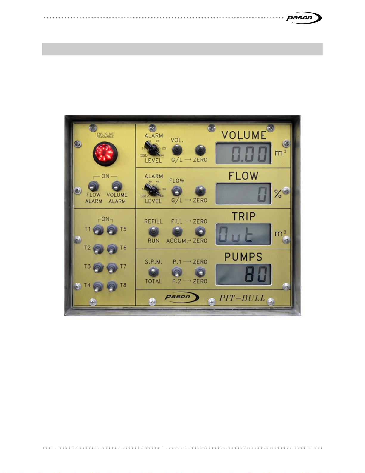
Figure 1 PVT face plate
The Pason PVT system is specifically designed to withstand the harsh environmental
extremes encountered in the Canadian drilling industry. The main display unit is
equipped with a 100-watt thermostatically controlled heater. This allows for operation in
ambient temperatures down to -45°C without any degradation in performance.
The unit is water-resistant and is designed to operate reliably under the adverse
conditions found on drilling rigs. All panel switches are environmentally sealed and have
a water-tight panel seal installed to provide protection from the elements. The system is
fully protected from input noise and over-voltage.
Page 6

Revised February 11, 2013
Revision 5 of DOCU006, © Copyright
Page 6 of 28
The Pason PVT system consists of two main units: the display unit and the junction box
(J Box). The J Box is provided so that field wiring connections can be made in a safe,
convenient location. The J Box also provides an excellent location for field personnel to
troubleshoot the system.
The display unit is the heart of the system, containing all the controls, switches, and
alarms. A 1” backlit Liquid Cryst al Dis play (LCD) is provided for each main function
monitored. A variety of information can be displayed about each function by using the
panel switches on the unit. The volume and flow sections monitor either gain/loss
readings or absolute values. The pump section monitors either strokes per minute or
total strokes for both pumps. The trip tank section monitors trip tank volume, individual
fill volume, or total accumulated fill volume.
An alarm is provided for both volume and flow gain/loss deviations. The alarms are fully
independent of each other and are adjustable. If one or both of the alarms are disabled,
a red warning light (LED) will flash to remind the operator to turn the alarm back on as
soon as possible. In addition to the volume and flow alarms, the trip tank system is
provided with both a high and low alarm to assist the operator in filling or draining the trip
tank.
Page 7

Revised February 11, 2013
Revision 5 of DOCU006, © Copyright
Page 7 of 28
1 Specifications
1.1 Display Unit Specifications
Input Power Requirements
Voltage 110 VAC, 50/60 HZ
Current 1.5 Amps
Environmental Specifications
Ambient Temperature
Relative Humidity 100% (Outdoor Use)
Hazardous Area
Classification
Physical Specifications
Dimensions (W-H-D) 14¾” x 123/8” x 7¼”
Weight 35 lbs.
Mounting Pipe Bracket
Box Material 1/16” Stainless Steel
Face plate Material 1/8” Aluminum
Viewing Windows Material 5 mil Safety Glass
–40 to 45
Class 1, Div. 2 (CSA)
(Excluding Mounting Brack et)
(Reverse Silk-Screened)
°C
Technical Specifications
Displays 4 Digit, 1” LCD (Backlit)
Display Accuracy
Volume Resolution 0.1 m3
Pit Accuracy
Flow Resolution 1%
± ½” of Fluid Level
± ½” of Fluid Level
Page 8

Revised February 11, 2013
Revision 5 of DOCU006, © Copyright
Page 8 of 28
Trip Resolution 0.01 m3
Pumps Resolution 1 Stroke/Minute
Chart Output
Chart Output Resolution 8 Bit (0.4%)
Functional Specifications
Displayed Functions Total Pit Volume
Main Pits Monitored Up To 8 Pits Plus Trip Tank
Volume Alarm Range 0.5 to 2.75 m3
0 to
± 20 mA (Programmable)
Volume Per Tank
Volume Gain/Loss
Return Flow Percent
Return Flow Gain/Loss
Trip Tank Volume
Individual Fill (Trip)
Accumulated Fill (Trip)
Strokes/Min. (Pump 1 & 2)
Total Strokes (Pump 1 & 2)
Flow Alarm Range 2.0 to 5.5%
Chart Recorder Output Volume, Flow and Trip (20 mA)
Alarm Horn 120 VAC Klaxon Type
1.2 J Box Specifications
Input Power Requirements
Input Voltage 14 VDC
Input Current 70 mA Typical
Environmental Specifications
Ambient Temperature
(Supplied Via Signal Cable)
(Limited to 100 mA)
–40 to 45
°C
Page 9

Revised February 11, 2013
Revision 5 of DOCU006, © Copyright
Page 9 of 28
Relative Humidity 100% (Outdoor Use)
Max. Internal Temperature
Hazardous Area
Classification
Physical Specifications
Dimensions (W-H-D) 155/8” x 12¾” x 8”
Weight 13 lbs.
Mounting Lugs (2)
Box Material PolyGlass
Technical Specifications
Reference Voltage
(Red to Black)
Short Circuit Current
(Red to Black)
Ambient + 2
°C
Class 1, Div. 2 (CSA)
6.2 VDC
(All Tanks–Open or Closed Circuit)
12 mA (All Tanks)
Signal Input Impedance
(White)
Open Circuit Voltage
(Red To Black)
Short Circuit Current
(Red to Black)
Open Circuit Voltage
(Red To Black)
Short Circuit Current
(Red To Black)
Functional Specifications
Field Inputs Main Pits (8)
100k ohm (All Tanks)
12 volts (Flow)
50 mA (Flow)
8.2 VDC (Pumps 1 & 2)
8.2 mA (Pumps 1 & 2)
Trip Tank
Flow
Pumps (2)
Page 10

Revised February 11, 2013
Revision 5 of DOCU006, © Copyright
Page 10 of 28
2 Installation
2.1 Installing in Hazardous (Class 1, Div. 2) Locations
Non-Incendive Field Wiring for Class 1, Div. 2, Groups B, C, & D
All field wiring connections provided in the Pason PVT system J Box are classified as
non-incendive and can be installed while the system is powered up or in the presence of
hazardous gases, providing that the field sensors/wiring are approved for that purpose.
Equipment Suitable for use in Class 1, Div. 2, Groups B, C, & D
All equipment provided with the Pason PVT system is suitable for use in Class 1, Div. 2,
Groups B, C, & D locations with the exception of the main power connector, which must
be installed in a safe (non-hazardous) area (e.g., the doghouse).
Suitability of Associated Equipment
The following associated equipment may be connected to the non-incendive field wiring
terminals without any further approval.
1. GEMS level switch or STI RPM series
(for Main Tanks (8) and Trip Tank Sensors).
2. Micro-Switch LSX Type Enclosed Waterproof Limit Switches or Equivalent
(Any Device With Only Switch Contacts For Pump 1 and 2 Sensors).
3. A 1 to 2k ohm Non-Inductive Type Potentiometer Suitably Housed
(for Return Flow Sensor).
2.2 Mounting the Equipment
Mounting the Display Unit
The display unit is equipped with a bracket for mounting on a 2” pipe. The unit should be
mounted somewhere near the driller’s console, slightly above eye level. Select a location
that provides maximum protection from any physical damage due to drilling activities.
Also, there must be a suitable route for the system cables to feed through the driller’s
console wireway. For maximum safety and reliability, run the cables in a manner that
prevents damage during normal rig operation or rig moves.
Page 11

Revised February 11, 2013
Revision 5 of DOCU006, © Copyright
Page 11 of 28
Mounting the J Box
The preferred location for the J Box is in the pump house. However it can also be
mounted under the sub-structure or on the tanks, if necessary. The location should also
be selected so that there is access to wireways.
Mounting the Tank Sensor
Tank sensors should be mounted in mud tanks as far away from any agitator blades as
possible. Short pieces of pipe may be welded to the bottoms of the tanks to prevent the
bottom of the probe from moving around. Regardless, install suitable brackets at the top
of the probe, so any lateral motion of the probe is prevented. Place probes clear of
skimmers, tank walls, and fill p ip es .
Mounting the Flow Paddle
The flow paddle is mounted to a saddle that is welded to the flow line during rig setup.
Note:
Proper flow paddle operation requires that the flow paddle be mounted above the level of the mud
in the shaker tank. If this is not done, reliable readings are virtually impossible. Generally, the
further up the pipe the flow paddle is mounted, the better it operates. On smaller rigs, it may not
be necessary to install the flow paddle at all due to insufficient fill.
Installing Wiring and Cabling
Instructions for installing sensor wiring and interconnecting cables are given below.
Sensor Wiring
Sensors should be wired using a 3-conductor, 20 AWG, overall foil-shielded (with shield
drain wire) type cable. The color combination of the cable is red, white, and black
(CBL038). This color-coding should match the labeling in the J Box, as well as the colorcoding used in the tank probes. The pump strokes, probes, and return flow sensor
should have lead wires installed that correspond to this color code, thereby simplifying
field installation. Lead wires inside the sensor housings can be connected using junction
blocks.
Important:
When wiring the sensors ensure that the shield does not touch the housing of the sensor, as this
will result in a ground loop and may cause noise problems in the system. Also, run tank wiring
underneath tank gratings and neatly tie the wiring to the bottom railings around the tanks. Sensor
wires must not be run in the same cable trays used for high voltage because this can lead to
abnormal voltages being induced into the signal cables (due to magnetic coupling), and a
reduced level of safety for rig personnel.
Page 12

Revised February 11, 2013
Revision 5 of DOCU006, © Copyright
Page 12 of 28
Note:
Connect the wiring according to the color and sensor definitions as outlined on the J Box circuit
board.
Once all connections have been made, any strain relief must be tightened so that a firm
tug on the wire does not cause it to slip through the strain relief.
At this point, the J Box lid may be secured, as no further
installation is required.
Unused tanks must be shorted out ("jumpered") with a small wire
between the white (W) and black (B) connections on the terminal
J Box. If a flow sensor is not being used, the "flow" channel in the
PVT J Box should also be "jumpered". A red PVT J Box plug (part
#CON237) should be used for each unused tank and the flow, to preserve the integrity of
the J Box seal.
Cable Installation
Interconnecting cables provided with the system are equipped with high-quality, militarystyle connectors. These connectors can provide many years of trouble-free
performance, if properly installed and cared for. When running cables between system
components, it is important that the free end of the cable be protected from mechanical
abuse that can occur from being dropped, etc. It is also critical to protect the connector
from water, dirt, oil, etc., so use cap protectors. It should reach its destination in a clean,
dry, and undamaged state.
Note:
When running the system cables, do not use excessive force to pull the cables through openings
in the rig: this can destroy the outer jacket of the cable.
Cables should be run in dry, out-of-the way locations. The cables are high-quality
products with good resistance to oil, chemicals, sunlight, water, and temperature
extremes; however, it is recommended that the cables be thoroughly cleaned between
jobs to extend their lifespan. If connector ends get dirty during installation, wash them
with an electrical cleaner before they are assembled. The cleaner is available in aerosol
cans (with a nozzle) and should be included as part of the field service equipment. Use
an electrical contact cleaner that is safe for plastics.
Note:
Prior to assembling the connector, apply a small amount of dielectric grease to one half of the
connector. This will help seal the connector and prevent the pins from corroding.
Page 13

Revised February 11, 2013
Revision 5 of DOCU006, © Copyright
Page 13 of 28
3 System Calibrati on
The Pason PVT is designed so that calibration is straightforward. No tools or meters are
required. All span and zero adjustments are made at the display unit, using panel
switches. Calibration factors are stored in non-volatile memory within the system, so if
the unit is powered down, you do not have to recalibrate.
3.1 Calibration Mode
Note:
Calibration should only be perf orm ed by a Pason field tec hnic ian.
To calibrate the Pason PVT, install the dummy 4-pin military connector into the terminal
marked Calibrate System on the underside of the PVT monitor.
Note:
The dummy connector can be thought of as a key, as it prevents unauthorized access to the
system calibration routines.
If the dummy connector is lost, take a short piece of wire with the ends bared to the
conductor and bend it into a “U”. Insert the ends into the two pins on the right-side of the
calibration connector’s plug, achieving a calibration mode signal of 8888.
Once in calibration mode, the panel switches and displays tak e on different functions.
The PUMPS display indicates the channel being calibrated. To change the channel, use
the PUMPS
ZERO switch to increase or decrease the channel shown on the PUMPS
display.
Once you select the proper channel, use the TRIP
ZERO switch to increase or decrease
the reading for that particular channel. The speed at which the reading changes can be
controlled by the FILL/ACCUM switch (this can be thought of as a fast or slow control).
When this switch is in the FILL position, the display changes quite quickly; while in the
ACCUM position, the display slows down considerably, thereby allowing the reading to
be stopped at the exact desired location.
To further simplify calibration, the system is programmed so that the channel being
calibrated shows up on the display that corresponds to that channel, while non-related
displays are blank. The channel number that corresponds to the trip tank span is shown
on the PUMPS display. In addition to the switches described above the flow, the ZERO
switch is used to set the flow zero point.
Page 14

Revised February 11, 2013
Revision 5 of DOCU006, © Copyright
Page 14 of 28
3.2 Calibrating the Volume System
Calibration of the volume system is done on a tank-by-tank basis. The basic procedure
is as follows:
1. Multiply the length, width, and height of the tank together to arrive at the tank
volume.
2. Pull the probe float all the way to the top of the tank and secure it.
3. Set the corresponding reading on the PVT monitor to match the calculated
tank volume.
Note:
The height measurement is obtained by measuring the distance from the bottom of
the tank to the center of the float; therefore, if the tank grating has been used as the
“top” of the tank, it is necessary to subtract half the thickness of the float from this
measurement to arrive at the true tank height. It is not necessary to compensate for
the probe zero offset error when calculating tank volumes, because the Pason PVT
software automatically adds the correct amount to the tank volume to compensate
for this.
3.3 Calibrating the Flow S ystem
To calibrate the flow system follow this procedure:
1. Set the system to calibrate mode (see Calibration Mode on page 13).
2. Use the PUMP ZERO switch to select channel 10 (Flow).
3. Place the flow paddle arm in the bottom position.
Figure 2: Flow paddle arm in the bottom position (zero flow)
4. Press down the FLOW G/L ZERO switch. The flow zero point has now been
established.
Page 15

Revised February 11, 2013
Revision 5 of DOCU006, © Copyright
Page 15 of 28
5. Set the flow span by holding the flow paddle arm in the top position
(maximum flow).
Figure 3: Flow paddle arm in the top position (maximum flow)
6. Use the FILL/ACCUM. ZERO switch to set the span to the desired value. The
flow span is usually set to read from 0 to 100, however, this may vary
depending on the application.
Note:
The flow zero point must be set before the flow span is set.
Page 16

Revised February 11, 2013
Revision 5 of DOCU006, © Copyright
Page 16 of 28
3.4 Calibrating the Trip System
Calibrating the trip tank is identical to calibrating the main mud tanks.
1. Select channel 9 on the PUMPS display.
2. Pull the probe float up to the top of the tank and secure it in this position.
3. Measure from the bottom of the tank to the middle of the float to find the tank
height.
4. Calculate the tank volume (L*W*H).
5. Use the FILL/ACCUM. ZERO switch to set the trip tank reading to the
calculated volume.
Note:
It is not necessary to compensate for the probe zero offset error (0.17 m) when
calculating trip tank volume. The system automatically calculates and compensates
for this.
At this point, set the trip high alarm level.
1. Use the PUMP ZERO switch to select channel 11.
2. Use the FILL/ACCUM. ZERO switch to adjust the setting until it reads about
0.5 m3 less than the trip tank volume (full). This will allow the operator a few
seconds to reach the fill pump switch.
3. Remove the dummy connector from the Calibrate System terminal, thus
returning the system to Run mode. This completes the calibration process.
Note:
You may have to reset the string weight in the Weight on Bit Trace on the DHC.
Page 17

Revised February 11, 2013
Revision 5 of DOCU006, © Copyright
Page 17 of 28
Calibration Channels
Switch
Setting Channel on PVT 1.03 and
lower
Channel on PVT 2.0 and
higher
Tanks 1-8 Span Setting 1-8 1-8
Trip Tank Span Setting 9 9
Flow Zero and Span Setting
10 10
(see note below)
Trip Tank High Alarm
11 13
Setting
Decimal Places (CDN) 12 14
Horn Sleep Feature (On,
11
Off)
Horn Sleep Delay 12
Table 1 Calibration Channels
Note:
Set the Flow Zero before Flow Span; Use the FLOW G/L ZERO switch to set the flow zero point.
Calibration Switches
P1/P2 - Zero Switch
Fill / Accum. Zero Switch
Flow G/L Zero Switch
Fill / Accum. Switch
Table 2 Calibration Switches
Note:
The selected channel is displayed on the PUMPS display.
Function in calibration mode
Select the channel to be calibrated
Increase/decrease settings
Set the Flow Zero Point (Channel 10)
Adjust the rate of change (fast/slow)
Page 18

Revised February 11, 2013
Revision 5 of DOCU006, © Copyright
Page 18 of 28
4 System Operation
4.1 Operating the Volume System
The volume system consists of:
• Eight tank switches
• A volume alarm switch (to enable/disable the alarm)
• An alarm level setting control
• A volume/gain-loss switch (to select which function to display)
• A gain-loss zeroing switch
• A warning light to indicate that the alarm is disabled
• A flow and volume alarm “snooze” feature (PVT versions 2.0 and higher)
The eight tank switches are used to sum up the active tanks in th e system. They are
also used to isolate individual tanks or to remove a tank from the active system, if
required.
The volume alarm is set to indicate gain/loss readings that exceed the limit. The alarm
level setting should reflect the maximum allowable gain. Fluid gains are usually
exponential in nature (as a result of gas rising in the wellbore), while fluid losses are
generally linear in nature and therefore not nearly as critical. For example, on a 4,000 m.
hole, if 1 m
3
of gas is forced into the wellbore (at the bottom), an alarm setting of 2 m3 will
detect a problem when the gas bubble reaches about 2,000 m. However, if the alarm is
set at 4 m
3
, the gas bubble will rise to a depth of 1,000 m. before an alarm is triggered.
This represents a 50% difference in warning time and clearly demonstrates how critical
the gain setting can be.
Analysis of fluid losses shows that alarm settings are far less critical. For example, if a
rig’s mud system contains a total of 100 m
3
of mud, an alarm setting of 0.5 m3 triggers
the alarm to go off when 0.5% of the total fluid has been lost. And an alarm setting of
3
1 m
triggers an alarm when 1% of the total fluid has been lost. Clearly, the difference
between these two figures is not very significant.
The VOLUME/GAIN-LOSS switch is provided to allow the operator to display either total
mud volume or volume gain-loss. The volume alarm is active regardless of which
position this switch is in. During normal operation, this switch should be in the gain-loss
position, as this provides the most critical information.
Page 19

Revised February 11, 2013
Revision 5 of DOCU006, © Copyright
Page 19 of 28
The GAIN-LOSS ZERO switches are used to periodically zero the gain-loss reading.
This is necessary if mud is added to the system, or if the reading has drifted down to the
alarm level due to normal drilling operation.
Note:
The GAIN-LOSS ZERO switches only operate when the switch is set to the GAIN-LOSS position.
This allows you to observe the gain-loss reading before zeroing it out.
The volume alarm switch on the left side of the panel allows the alarm to be disabled
when the mud volume is not stable enough for proper operation. When the volume (or
flow) alarm is disabled, the panel warning light blinks to remind you to turn the alarm
back on as soon as possible.
The volume/gain-loss readings are displayed on a 1”, 4-digit LCD (Liquid Crystal
Display). The maximum volume that can be
displayed is 800 m
loss that can be displayed is
3
, while the maximum gain-
±99.9 m
3
.
If an alarm condition is present (volume), the horn sounds to indicate an alarm has
occurred (volume or flow).
Note:
The red LED blinks when one or both alarms are set to OFF (VOLUME or FLOW).
The volume alarm “snooze” feature is available for RigComm compatible PVTs running
firmware version 2.0 and higher. This feature allows you to temporarily mute the volume
alarm. The PVT can be set to snooze the alarm for between 1 and 10 minutes. When the
alarm is snoozed, “SLEEP” is displayed on the VOLUME LCD. For more information on
the snooze feature, see DOCU196 PVT Alarm Snooze Quick Tips at help.pason.com.
Note:
The channel configuration was changed for PVT firmware versions 2.0 and higher. See Table 1
Calibration Channels on page 17.
Page 20

Revised February 11, 2013
Revision 5 of DOCU006, © Copyright
Page 20 of 28
4.2 Operating the Flow System
The flow system operates in a manner very similar to the volume system. Flow is
displayed as a percentage of full rather than as a volume.
Proper operation of the flow system requires some knowledge of the flow sensor
(paddle) as well as some of the conditions encountered in the return flow system. The
flow paddle consists of a paddle that rides on the surface of the mud and is attached to a
shaft, which rotates a potentiometetop r, thereby producing a signal corresponding to
shaft position. The purpose of the flow paddle is to produce a signal that is related to the
amount of mud flowing in the return line. For example, if the pump rate is doubled, the
reading on the monitor roughly doubles. The flow system doesn’t give an exact value for
the return flow system (affected by slope, temperature, viscosity, obstructions, etc.), but
it establishes a relative number (benchmark) for normal flow conditions. This number
may increase or decrease depending on variables such as viscosity or temperature, but
if you are aware of these factors, you gradually get used to interpreting the data supplied
by the flow system.
Table 3: Pason flow paddle
The flow paddle is calibrated so that the output varies from 0 to 100% as the flow paddle
moves from its bottom position through to its top position. The alarm level setting is a
percentage of the full flow line as opposed to a
percentage of the actual flow reading. For
example, if a flow line is calibrated to read from 0
Page 21

Revised February 11, 2013
Revision 5 of DOCU006, © Copyright
Page 21 of 28
to 100% and the normal reading is 20%, then an alarm level of 5% will cause an alarm to
occur at 15% or 25%, depending on whether an increase or decrease has occurred.
Setting the alarm level varies from rig to rig, as some rigs have very smooth flow lines,
while others are quite turbulent. The alarm level should be set as low as possible without
causing alarms due to normal turbulence. The flow alarm can be disabled so that
operations such as tripping or adding pipe can be performed without causing the alarm
to go off. When the flow alarm is disabled, the panel warning light blinks to remind the
operator to turn it back on as soon as possible.
Note:
On some rigs with very flat flow lines or obstructions that cause “shaling”, it may not be possible
to achieve a reliable flow reading. In cases like this, it may be better not to install the flow paddle
at all.
The flow alarm “snooze” feature is available for RigComm compatible PVTs running
firmware version 2.0 and higher. This feature allows you to temporarily mute the volume
alarm. The PVT can be set to snooze the alarm for between 1 and 10 minutes. When the
alarm is snoozed, “SLEEP” is displayed on the VOLUME LCD. For more information on
the snooze feature, see DOCU196 PVT Alarm Snooze Quick Tips at help.pason.com.
Note:
The channel configuration was changed for PVT firmware versions 2.0 and higher. See Table 1
Calibration Channels on page 17.
Page 22

Revised February 11, 2013
Revision 5 of DOCU006, © Copyright
Page 22 of 28
4.3 Operating the Tr i p Tank System
The Pason PVT trip tank instrumentation allows you to monitor three separate aspects of
the trip operation: the trip tank volume, individual fills volume, and the total accumulated
fill volume. First fill the trip tank to the specified level. Then you can monitor the actual
trip tank volume by placing the REFILL/RUN switch in the REFILL position.
Once the trip tank has been filled, initialize the trip monitor. Assuming that this tank is the
first tank of the trip operation, the initialization procedure is outlined in the following
steps:
1. Place the REFILL/RUN switch in the RUN pos ition.
2. Place the FILL/ACCUM. switch in the ACCUM. position.
3. Use the ACCUM. ZERO switch to initialize (zero) the ACCUM. reading.
4. Place the FILL/ACCUM. switch in the FILL position.
5. Use the FILL ZERO switch to initialize (zero) the FILL reading.
When the stands have been removed from the hole and a hole fill is required, the trip
display shows the amount of mud being pumped into the hole. When the display shows
that the required amount of mud has been
pumped into the hole, the pump is shut off
and the FILL ZERO switch is used to zero the
FILL reading again. The quantity of mud that was pumped into the hole is retained by the
system for addition to subsequent fill operations. The FILL/ACCUM switch can be
switched over to ACCUM. at any time to see the total amount of mud that has been
pumped down the hole.
If you wish to see the actual volume of the trip tank, you may place the REFILL/RUN
switch in the REFILL position. However, don’t do this while mud is being pumped down
the hole. When the REFILL/ RUN switch is in the REFILL position, any change in the trip
tank volume is not reflected in the total accumulated reading. This allows you to refill the
trip tank during multiple tank trips.
Important:
During multiple tank trips it is important that the REFILL/RUN switch be placed in the REFILL
position when refilling the tank. If this is not done, the amount of mud pumped from the main
system into the trip tank will be subtracted from the total accumulated reading.
Forgetting to switch from RUN to REFILL during multiple tank trips should not be a
problem because the only way to see the actual trip tank volume (when filling the tank) is
Page 23

Revised February 11, 2013
Revision 5 of DOCU006, © Copyright
Page 23 of 28
to place the switch in the REFILL position. Conversely, forgetting to switch back to RUN
when the tank has been refilled should not be a problem, as the only way to get a zero
reading on the fill display is to have the switch in the RUN position.
In addition to the above features, the trip tank system is also equipped with high and low
alarms. The low alarm is used to warn you that the trip tank level has decreased to
approximately 0.44 m in height (not adjustable). If the alarm is triggered during a fill
operation, this allows the fill to be safely completed without running the tank dry. The
high alarm is used to warn the operator to shut the fill pump off to prevent overflowing
the trip tank. The high alarm is based on volume and should be set during system setup
by a Pason field technician. The high alarm is normally set to go off at about 0.5 m
before the tank is full, to allow the operator a few seconds to disable the fill pump.
4.4 Operating the Mud Pump System
3
Select the function to be monitored by using the SPM/TOTAL switch to select either
strokes per minute or total strokes. Next, select the pump to be observed by using the
P.1/P.2 switch.
The system monitors and keeps track of total strokes for both pumps, even when both
pumps are running simultaneously. If it is necessary to zero a total stroke reading, select
the total stroke function, and then select the desired pump. Use the corresponding
ZERO switches to clear the reading.
The number of strokes per minute is continuously monitored for both pumps, and
therefore no waiting period is necessary when
switching from one pump to the other. The
number of strokes per minute is calculated on
a on a stroke-by-stroke basis. This means that the update time for strokes per minute
(spm) is tied directly to pump speed. For example, a pump running at 30 spm will be
updated every 2 seconds.
Page 24

Revised February 11, 2013
Revision 5 of DOCU006, © Copyright
Page 24 of 28
5 System Maintenance
5.1 Maintenance Warnings
This equipment has been approved for use Class 1, Division 2 areas.
Important:
Substituting components may impair suitability for Class 1, Division 2, thereby resulting in an
explosion hazard. If you are not absolutely certain about the suitability of replacement parts,
contact the manufacturer before proceeding.
Caution:
If the main display unit has to be opened for service, first disconnect the power and ensure the
area is known to be non-hazardous. Failure to observe this precaution can result in an explosion
hazard.
The main display unit of the system operates at line voltage (120 VAC), which constitutes a shock
hazard. If it is necessary to troubleshoot the system with the power on, use extreme caution.
Once the problem has been identified, remove the power. Do not attempt to replace or disconnect
any parts while the power is on.
5.2 Troubleshooting
The majority of problems encountered in the field are related to damaged field sensor
wiring or improperly installed/maintained cables and connectors. Sensors can also
become faulty due to their placement and environment.
Troubleshooting the Volume System
If the volume reading on the display unit is erratic or reading too high/low and the rest of
the system appears to be functioning properly, the problem is likely a broken or shorted
sensor wire. Use the traces on the DHC to determine where any historical spikes
occurred.
Important:
Always check the data cable connection from the PVT to the J Box first. You should only see 3-4
threads.
Note:
The VOL/G/L switch should be set to the VOL function. If the display reads zero, start turning the
tank switches on one at a time, and check to see if the readings are abnormal. This quick check
often isolates the faulty tank circuit, thereby eliminating the need to check all the tank sensors
and wiring. If one tank circuit gives abnormal readings, you can determine if the problem is in the
sensor wiring, the probe, or is an internal system problem.
Page 25

Revised February 11, 2013
Revision 5 of DOCU006, © Copyright
Page 25 of 28
A quick way to determine if the problem is internal is to disconnect the faulty circuit
(inside the J Box) and replace it with a known good circuit. For instance, if Tank #5 is
giving problems, disconnect the wiring to Tank #5 and replace it with the sensor wiring
from a tank that is working properly. Then return to the PVT monitor and see if the
problem still exists. If this fixed the problem, check the wiring, sensor, and J Box.
If the problem still exists, check the sensor wiring. Following the wire from the probe to
the J Box usually uncovers a damaged area on the wire. If no problem is apparent, try
replacing the wire, since it may be faulty inside. If this procedure indicates an internal
system problem, check the main signal cable and its connectors. If the connectors
appear to be installed correctly (not loose), remove them, and check for any sign of
moisture, corrosion, dirt, etc. If evidence of contamination is found, clean and lubricate
the connectors. Replace the connectors and try the system again. If the problem
persists, follow the cable from the PVT monitor to the J Box while looking for any signs
of damage.
If only one tank circuit is acting up, the problem is probably due to probe/wiring troubles.
If more than one tank circuit is acting up, the problem is probably the module, data
cable, or PCB board. If readings differ between the DHC and the PVT, the problem is
probably a faulty cable or module.
To replace the electronics module:
1. Disconnect the power.
2. Remove the 16 face plate screws.
3. Remove the face place using Tool 132 (PVT Face plate pry bar).
4. Locate the module in the upper left corner of the box, and then remove it by
disconnecting the three d-sub connectors using a small screwdriver. Also
remove the screws holding the module in place.
5. Switch out the module, ensuring all screws are tightened.
6. Replace the leads.
7. Turn on the power and try the unit.
If the unit still doesn’t work, return it to Pason for inspection.
Page 26

Revised February 11, 2013
Revision 5 of DOCU006, © Copyright
Page 26 of 28
Troubleshooting the Flow System
If the flow display reading is abnormal and the rest of the system seems to be working
properly, the problem is likely in the sensor wiring or sensor. A quick way to test the
complete flow system from the J Box to the sensor is to connect the flow wiring to one of
the tank input connectors (in the J Box). The trip tank is the best choice as the FILL
ZERO switch can be used to establish a zero point.
After hooking up the wiring, check the PVT monitor to see if the display shows a
reasonable figure. If not, the problem lies in the field wiring, sensor, or the J Box. As a
last resort, return to the PVT monitor and ensure the display is functioning properly.
Abnormal readings may require adjustment of the FLOW LED at the potentiometer. If
not, the problem is in the sensor wiring. Check the wiring from the flow sensor to the
JBox and repair or replace it. The system should work. If the problem is found to be an
internal one, go to Troubleshooting the Volume System on page 24 to determine the
next course of action.
Troubleshooting the Mud Pumps System
Pump strokes are sent from the EDR (if the pump stroke sensors are connected to the
EDR). If strokes are present on the DHC but not on the PVT monitor, check the 4-pin
connecting cable (CBLASS002).
Note:
Pump strokes can come from either the PVT or the EDR. If the strokes are coming from the EDR
and are not showing up on the PVT, there could be a communications problem between the two
systems. If the strokes are coming from the PVT (mechanical switches) the problem could be the
wiring, J Box, or PVT.
If the problem is found to be an internal system problem, use a mechanical stroke
counter to verify that strokes are being recorded correctly.
General Troubleshooting
If the system is acting up, follow these steps to isolate the problem:
1. Ensure that the unit is plugged in and that the power outlet is working.
2. Inspect the AC plug for loose wiring or corrosion.
3. Check the power to the J Box by hooking up a voltmeter between the circuit
board mounting plate and the binding post on the circuit board (marked V+).
The voltmeter should read approximately 14.3 volts. If the reading doesn’t
Page 27

Revised February 11, 2013
Revision 5 of DOCU006, © Copyright
Page 27 of 28
match, the main signal cable should be inspected for damage. If any
problems are found with the cable it should be repaired or replaced, even if
no visual damage is evident. Also check for loose or dirty connectors.
4. Return to the J Box and repeat the power test (if the results are still not
correct, the problem is likely with the power supply in the main display unit).
5. If the system does nothing when plugged in, the problem is most likely a
blown fuse. There are two fuses in the system. The first (½ amp slo-blo)
protects the transformer supply, and the second (2 amps) protects the horn
and the heater. If the system is completely dead, then the ½ amp fuse is most
likely blown. To replace the fuse, DISCONNECT THE POWER to the system
and remove the face plate. If the new fuse blows after the power is turned
back on, then the cause must be isolated. DO NOT SUBSTITUTE A
LARGER FUSE, as doing so leads to larger problems.
6. Test the power outlet. The voltage measured at the outlet should be between
110 and 125 VAC. If this isn’t the case, corrective action must be taken. If the
power outlet is functioning properly, the problem is likely in the power supply.
Disconnect the main power and remove the display unit face plate. Replace
the power supply. Temporarily replace the face plate, using 2 or 3 screws and
try the system again.
7. If the problem is still present, remove the face plate and replace the
electronics module.
8. If the system is still not working, return it to Pason for further testing.
Troubleshooting Summary
The best place to start troubleshooting is at the J Box, where the problem can be
isolated to either the field side or the system side of the J Box. Problems on the field side
of the J Box are easily narrowed down by substitution of known good parts or simulators.
Problems on the system side can usually be broken down into three problem areas:
power supply, electronics module, or data cables. If only one function is acting
improperly, the problem is likely an electronics or cable problem. If the whole system is
acting up, the problem is likely a power supply problem. If in doubt as to what
component is at fault when servicing the PVT monitor, replace the power supply first. If
this does not fix the problem, leave the new power supply in place and replace the
Page 28

Revised February 11, 2013
Revision 5 of DOCU006, © Copyright
Page 28 of 28
electronics module. This is the safest method to use, as it prevents new parts from being
damaged by old parts that are malfunctioning.
Note:
Problems with the display board are usually self-evident (e.g., missing display segments etc.)
Remember that the majority of problems are on the field side of the J Box, so ensure
that this part of the system is tested before opening the PVT monitor. It is also important
to eliminate any possibility that the power cord, power connector, or power outlet is
causing the problem before opening the PVT monitor.
Note:
Take proper precautions when opening the PVT monitor, as there is sufficient voltage (120 VAC)
to constitute a shock hazard.
When replacing the face plate, be sure to tighten the screws down evenly and in a
random pattern. Failure to do this could cause damage to the gasket or the face plate,
resulting in a box that leaks.
If the general procedures outlined in this section are followed, troubleshooting the
system should be a relatively straightforward task. It has been shown that an intimate
knowledge of the internal electronics is not necessary for field servicing. The most
common problems with the PVT are as follows:
• The 4-pin cable is screwed into the 5-pin connector (P1/P2) on the PVT.
• The data cable is not screwed in all the way, or it’s cross-threaded.
• The Woodhead connector is missing the ground pin.
• There’s electrical interference between the PVT and DC cables strung too
closely to the PVT.
 Loading...