

Page 1
P
P
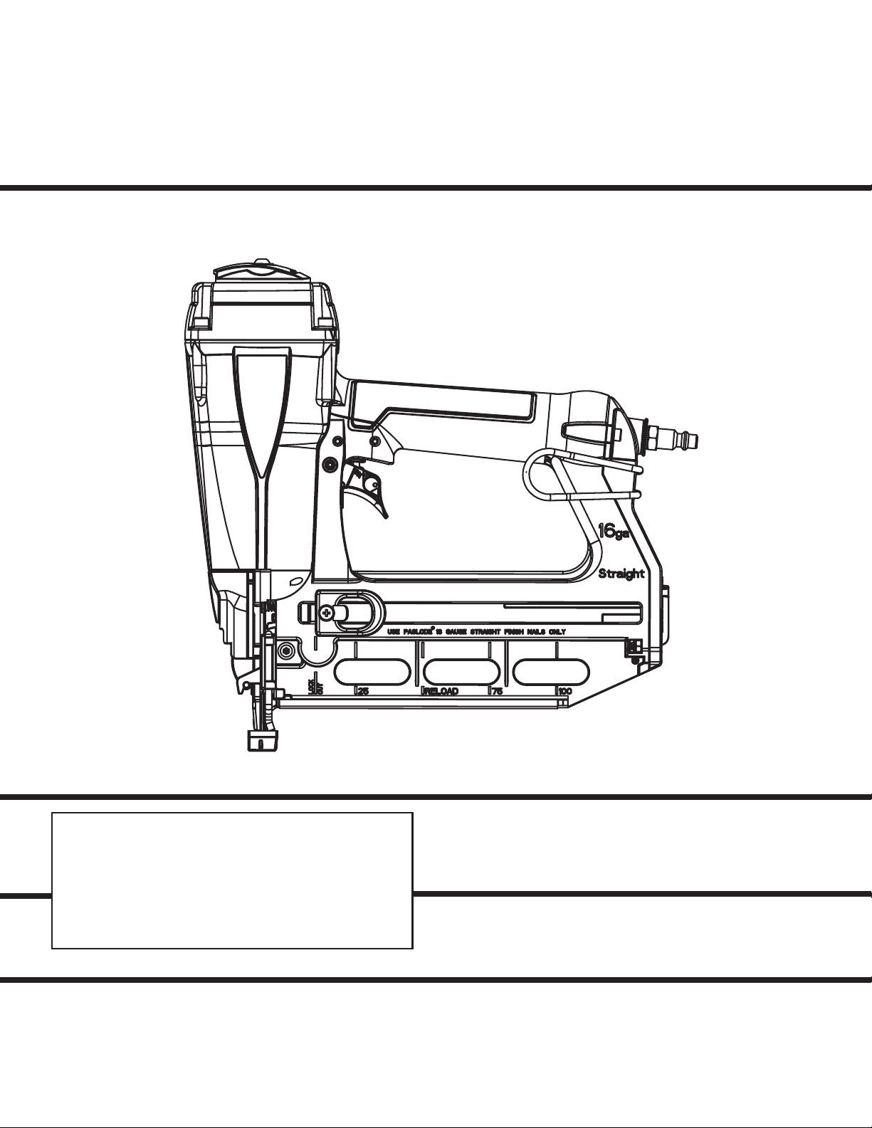
MODEL T250S-F16
16 Gauge Straight
Finish Nailer
IMPORTANT!
DO NOT DESTROY
It is the customer’s responsibility to have all
operators and service personnel read and
understand this manual.
OPERATING MANUAL AND
TOOL SCHEMATIC
Page 2
INTRODUCTION
The PASLODE® T250S-F16 finish nailer is a quality-built tool designed for use in residential
trim applications. This tool will deliver efficient, dependable performance when used according
to the manufactures guidelines. Please study this manual including the safety instructions to
fully understand the operation of this tool.
TOOL AND FASTENER SPECIFICATIONS ....................................................... 3
SAFETY INSTRUCTIONS ...................................................................................4
TOOL OPERATION .............................................................................................. 5
EXPLODED VIEW AND SPARE PARTS LIST .............................................10-11
ACCESSORIES ..................................................................................................12
TOOL WARRANTY AND LIMITATIONS
2
Page 3

TOOL AND FASTENER SPECIFICATIONS
TOOL SPECIFICATIONS
MODEL NO. T250S-F16 (Part# 501680)
HEIGHT 11.3"
WIDTH 3.1"
LENGTH 11.5"
WEIGHT 3.9lbs.
OPERATING PRESSURE 80 to 120 p.s.i. (5.5 to 8.3 bars)
ASSEMBLY HARDWARE SYSTEM Metric
FASTENER SPECIFICATIONS
NAIL LENGTH 3/4" - 2-1/2"
SHANK DIAMETER 16 gauge
TOOL AIR FITTINGS:
This tool uses a 1/4” N.P.T. male plug. The inside diameter should be .28” (7mm)
or larger. The fitting must be capable of discharging tool air pressure when
disconnected from the air supply.
OPERATING AIR PRESSURE:
80 to 120 p.s.i. (5.5 to 8.3 bars). Select the operating air pressure within this range
for best tool performance.
DO NOT EXCEED THIS RECOMMENDED OPERATING PRESSURE.
3
Page 4
SAFETY INSTRUCTIONS
SAFETY FIRST
These safety instructions provide information necessary
for safe operation of Paslode
TO OPERATE THE TOOL UNTIL YOU READ AND
UNDERSTAND ALL SAFETY PRECAUTIONS AND
MANUAL INSTRUCTIONS.
WEAR EYE AND HEARING PROTECTION
Always wear hearing and eye protection devices, that
conform to ANZI Z87.1 requirements, when operating or
working in the vicinity of a tool. As an employer you are
responsible for enforcing the use of eye protection.
Wear hard hats in environments that require their use.
THE TOOL MUST BE USED ONLY FOR THE PURPOSE FOR WHICH IT WAS DESIGNED
Do not throw the tool on the floor, strike the housing in
any way or use the tool as a hammer to knock
material into place.
NEVER ENGAGE IN HORSEPLAY WITH THE TOOL
The tool is not a toy so do not use it like one. Never
engage in horseplay with the tool or point it at yourself
or any other person, even if you think it is not loaded.
NEVER ASSUME THE TOOL IS EMPTY
Check the magazine for fasteners that may be left in the
tool. Even if you think the tool is empty or disconnected,
never point it at anyone or yourself. Unseen fasteners
could fire from the tool.
NEVER CLAMP THE TRIGGER IN A LOCKED OR
OPERATING POSITION
The trigger of the tool must never be tampered with,
disabled or clamped in a locked or operating position
since this will cause the tool to drive a fastener any time
the work contacting element depressed.
DO NOT LOAD FASTENERS WITH THE AIR LINE
CONNECTED, OR WITH THE TOOL TRIGGER OR
WORK CONTACTING ELEMENT DEPRESSED
When loading fasteners into the tool be sure you
disconnect the air line and that you do not depress the
trigger or work contacting element.
OPERATE THE TOOL ONLY ON A WORKPIECE
The tool should be operated only when it is in contact
with the workpiece. Even then you should be careful
when fastening thin material or working near the edges
and corners of the workpiece since the fasteners may
drive through or away from the workpiece.
DO NOT DISABLE OR REMOVE THE WORK CONTACTING ELEMENT
This tool is equipped with a safety mechanism, called a
work contacting element, to help prevent
accidental firing. Never tamper with, disable or remove
the work contacting element. Do not use the tool unless
the work contacting element is working properly. The
tool could fire unexpectedly.
®
tools. DO NOT ATTEMPT
DISCONNECT THE TOOL WHEN NOT IN USE
Always disconnect the tool from the air line when it is
not in use, when you leave the work area or when
moving the tool to a new location. The tool must
never be left unattended because people who are not
familiar with the tool might handle it and injure
themselves or others.
CARRY THE TOOL ONLY BY THE HANDLE
Always carry the tool by the handle only. Never carry
the tool by the air hose or with the trigger depressed
since you could drive a fastener unintentionally and
injure yourself or someone else.
DO NOT WEAKEN THE TOOL HOUSING
The tool housing is a pressure vessel and should never
be weakened by having your company’s name, area
of work or anything else stamped or engraved into its
surface.
DISCONNECT THE TOOL WHEN PERFORMING
REPAIRS AND CLEARING JAMS
Never attempt to clear a jam or repair a tool unless you
have disconnected the tool from the air line and
removed all remaining fasteners from the tool.
ALWAYS USE THE PROPER FITTING FOR THE
TOOL
Only MALE pneumatic type air connectors should be
fitted to the tool, so that high pressure air in the tool is
vented to atmosphere as soon as the air line is
disconnected.
NEVER install FEMALE quick disconnect couplings on
the tool. Female couplings will trap high pressure air
in the tool when the air line is disconnected, leaving
the tool charged and able to drive at least one fastener.
DO NOT EXCEED THE MAXIMUM RECOMMENDED
AIR PRESSURE
Operate the tool only at the recommended air pressure. Do not exceed the maximum air pressure marked
on the tool. Be sure the air pressure gauge is
operating properly and check it at least twice a day.
Never use any bottled air or gases such as oxygen to
operate the tool since they could cause the tool to
explode.
INSPECT TOOL FOR PROPER OPERATION
Clean the tool at least daily and lubricate as required.
Never operate a dirty or malfunctioning tool.
USE ONLY PASLODE RECOMMENDED PARTS AND
FASTENERS
Use only parts and fasteners specifically designed and
recommended by Paslode for use in the tool and for
work to be done. Using unauthorized parts and
fasteners or modifying the tool in any way creates
dangerous situations. Replace all missing warning
labels---refer to tool schematic for correct placement
and part number.
WARNING
Failure to follow any of the above instructions could result in severe personal
injury to tool user and bystanders or cause damage to tool and property.
Contact your local Paslode Representative for presentation of Paslode’s Safety Awareness Program
4
Page 5

TOOL OPERATION
Fasteners
The Paslode T250S-F16 Finish Nailer drives
Paslode® 16 gauge fasteners designed to be used
with the tool. The use of fasteners that do not meet
Paslode standards could cause tool damage and will
void all warranty claims.
Loading Fasteners
STEP 1: Align the heads of the Paslode 16 ga.Finish
nails to the brad channel in the rear of the magazine
and insert one or two strips. Push the nails strips
forward.
STEP 2: Next, while applying pressure to the release
lever, pull the follower toward the rear of the
magazine until the follower passes the last strip of
fasteners. Release the lever on the follower and let
the follower push the nails forward into the nose of
the tool.
Depth of Drive Adjustment
Disconnect the air supply.
The depth of drive adjustment is done by turning the
adjustment wheel as shown by the arrows on the side of
the tool.
Turn
adjustment
wheel in
either
direction
Clearing a Jam
An occasional problem you may encounter is a jammed
fastener. Because of the unique design of the Paslode
Finish Nailer, clearing a jammed fastener is easy:
1. Disconnect the air supply.
2. Pull the latch, releasing front guide. Pivot front guide
forward.
3. Clear jam, and push driver blade back up to its normal
position.
4. Close front guide and latch it. Check that work
contacting element moves freely.
When the follower reaches the reload area, marked
on the side of the magazine, you may insert a new
strip of nails. When the follower arrow reaches the
lockout area the tool automatically locks the tool to
prevent the tool from operating. To unlock the tool,
simply reload another strip of nails.
Lockout Feature
The purpose of this feature is to prevent needless
blank cycling, which could mar woods and damage tool components. Ten (10) nails will be left in
the magazine when the follower reaches the
lockout area. When changing fastener length or
loading at the beginning of the work day, you
should inspect the magazine and nose for any
fasteners left in the tool. These nails will not be
visible unless you open the nose of the tool.
5
Page 6

TOOL OPERATION
Trigger Methods:
The Paslode T250S-F16 Finish Nailer has a triggering
system than can be switched from sequential to contact
trip. To switch the trigger, press in the round orange
button on the right side of the trigger and rotate the left
side of the button to the desired triggering method. The
TTT indicates contact trip and the T indicates sequential
operation.
Successive (Bounce) Driving -
Grasp the handle firmly.
Squeeze the trigger and move the tool along the
workpiece with a bouncing motion, depressing the work
contacting element at the points where you want to drive
a fastener.
Keep the trigger depressed and continue to bounce the
work contacing element against the workpiece, positioning the tool above as carefully as possible.
When the desired number of fasteners have been
driven, release the tool trigger to avoid unintentional
fastener discharge.
Reversible Belt Hook:
The belt hook can be changed from the left hand side of
the tool to the right hand side. To change the position,
squeeze the base of the belt hook and remove it from the
tool and position it on the desired side.
➔
➔
➔
➔
Adjustable Exhaust:
The direction of the exhaust air can be changed by
rotating the orange air deflector on the cap of the tool.
Sequential Operation -
The sequential setting T prevents succesive or "bounce"
driving.
Depress the work contacting element and hold it
against the work surface before pulling the trigger.
After each fastener is driven, completely release the
trigger and lift the tool from the work surface.
6
Page 7

MAINTENANCE
Paslode® tools are built for ease of maintenance. A few
simple details will assure trouble-free operation and long
tool life. Anyone who uses or maintains the tool must read
the safety and maintenance instructions. Study the schematic drawing before starting any repairs on the tool.
Air-operated tools must be inspected periodically, and worn
or broken parts must be replaced to keep the tool operating
safely and efficiently. Also the items on the maintenance
chart must be checked often.
Cold Weather Care
❑ Open the drain on the air compressor tank to drain any
moisture at least daily in extremely cold or humid weather.
A few ounces of anti-freeze in the tank will keep the air
free of frost.
Testing the Tool After Servicing
After replacing any part or parts, it is important to check
the tool for proper operation. This ensures that the tool
was put together correctly, is safe to use, and will perform
the job properly.
❑ Ensure that all hardware is tight.
❑ Ensure that the work contacting element is installed
correctly in relation to the trigger, and that both parts
move freely.
When temperatures are below freezing, tools should be
kept warm by any convenient, safe method. If this is not
possible, the following procedure should be used to warm
up the tools.
❑ Reduce the regulated air pressure to 30 psi.
❑ Remove all fasteners from the tool.
❑ Collect an air line and blank fire the tool. The reduced
air pressure will be enough to free-fire the tool. Slow speed
operation tends to warm up the moving parts. Slowing up
the piston helps the bumper and the O-rings to become
pliable.
❑ Once the tool is warmed up, readjust the regulator to
the proper working pressure and reload the tool.
❑ Tool operators working outdoors or in unheated areas in
extremely cold temperatures should also:
❑ Ensure that the magazine is properly attached.
❑ Ensure that the required safety information on the tool
is legible.
❑ Use only Paslode approved fasteners in the tool, and
ensure that they are correct for the application.
❑ Ensure that a male air fitting is securely connected to
the tool.
❑ Test the tool by driving fasteners into a workpiece
identical to the tool's application.
❑ Check the tool for air leaks during testing and for the
proper sequence of operation.
❑ Ensure that all fasteners are driven to the same depth
and that the crown of the fastener is flush with the
workpiece.
Tool Lubrication
It is most important that the tool be properly lubricated by
keeping the air line lubricator filled and correctly adjusted.
Without proper lubrication the tool will not work properly
and parts will wear prematurely.
Use Paslode pneumatic oil with antifreeze in the
lubricator, Part No. 219090 (8oz.)
Once a week, depending on the amount of tool use,
take the tool apart and wash away any sludge with
degreaser cleaner (Paslode Part No. 219086) to
keep the tool operating efficiently.
Cleaning the air-operated tools with solvents removes the
thin coating of grease applied to the cylinder wall and
O-rings at the factory. To replace this coating of grease,
use Chemplex grease (Paslode Part No. 403734).
Use the proper lubricant in the air line lubricator. The
lubricator should be of low air flow or changing air flow
type, and should be kept filled to the correct level. Use
only Paslode recommended lubricants. Substitutes may
harm the rubber compounds in the tools O-rings and other
rubber parts. Paslode Part No. 403720 is a pneumatic
lubricating oil specially made for pneumatic applications.
If a filter/regulator/lubricator is not installed on the air
system, air operated tools should be lubricated at least
once a day with 6 to 20 drops of oil, depending on the
work environment, directly through the male fitting in the
tool housing.
Most minor problems can be resolved quickly and easily
using the maintenance table that follows. If problems
persist, contact your Paslode dealer for assistance.
7
Page 8

MAINTENANCE
ACTION WHY HOW
Drain air line filter (daily).
Keep lubricator filled.
Clean filter element, then blow
air through filter in direction
opposite to normal flow.
Check that all screws on tool
are tight.
Keep work contacting elelment
working properly.
Keep magazine and feeder
mechanism clean.
Prevent accumulation of
moisture and dirt.
Keep tool lubricated.
Prevent clogging of filter with
dirt.
Prevent air leakage and promote efficient operation.
Promote operator safety and
efficient tool operation.
Prevent jamming of fasteners.
Open manual petcock (most
air supply systems have such
a valve).
Fill with Paslode pneumatic
tool lubricant. Part No.
219026.
Wash with soap and water or
follow manufacturers instructions.
Check screws daily.
Blow clean daily.
Blow clean daily.
Lubricate "O" rings that are
replaced.
Use only Paslode replacement
parts.
Assure long life and proper
operation of tool.
Keep tool operating efficiently
and maintain Paslode tool
warranty.
8
Use Chemplex grease, Part
No. 403734.
Order any replacement parts
needed from Paslode Dealer.
Page 9

OPERATOR TROUBLESHOOTING
PROBLEM CORRECTIVE ACTION
Fasteners will not drive completely into wood.
Fasteners penetrate properly during normal
operation, but won't drive fully at faster speeds.
Fasteners drive too deeply into wood.
Fastener jams in nose of tool.
Tool skips during operation - no fasteners are driven
from time to time.
Adjust the
Increase air pressure (do not exceed 120 psi).
Increase air flow to tool -- use larger air lines
(3/8 inch ID minimum).
Adjust the
Reduce air pressure.
Open front guide latch, release jammed fastener,
and close latch securely.
Check magazine for proper fasteners. Magazine
follower should slide freely. Clean as needed to
remove debris.
depth of drive adjustment (retract length).
depth of drive adjustment (extend length).
Tool operates, but no fasteners are driven.
Air leaks at cap when tool is connected to air.
Make sure correct fasteners are being used.
Use fasteners that meet Paslode® specifications only.
Increase air flow to tool -- use larger air lines
(3/8 ID minimum).
Adjust work contacting element where available.
Check magazine for proper fasteners. Fasteners
should slide freely with no follower pressure.
Open front guide latch or loosen magazine knob and
check for jams or debris in the nose area. Clear as
necessary.
Increase air pressure (do not exceed 120psi).
Tighten cap screws.
9
Page 10

PARTS LEGEND T250S-F16, 501680
1 501885 1 T.H.S.C.S. 1/4-20 x 1/2
2 501896 1 Flat Washer
3 501899 1 Deflector
4 501901 1 Bolt
5 501902 1 Cap
6 501903 1 Seal
7 501904 1 Spring, Main Valve
*8 501905 2 O-Ring
9 501906 1 Head Valve Piston
10 501907 1 O-Ring
*
11 501908 1 Collar
*
12 501909 1 Packing
13 501910 1 Piston Ring
*
*
14 501911 1 O-Ring
15 501912 1 Driver Blade
*
16 501920 1 Cylinder Press Ring
17 501913 1 O-Ring
18 501914 1 Cylinder
19 501915 1 Cylinder Ring
20 501916 1 Cylinder Spacer
21 501917 1 O-Ring
*
22 501918 1 Bumper
23 501919 1 Driver Guide
*
24 501921 1 O-Ring
*
25 501922 1 O-Ring
26 501923 1 Plunger Cap
27 501930 2 Spring Pin
28 501924 1 Valve Plunger
*
29 501925 2 O-Ring
*
30 501926 1 O-Ring
31 501927 1 Spring
32 501928 1 Plunger
33 500999 2 O-Ring
34 501929 1 Trigger Valve Head
35 501932 1 Spring
36 501933 1 Trigger Unit
37 501965 2 Tap Bolt
38 501962 1 Lock Nut
39 501964 1 Magazine B
40 501961 1 Counter Sunk Screw
41 501934 1 Trigger Pivot Pin
42 501935 1 Housing
43 501936 1 O-Ring
44 501937 1 End Cap
45 501092 1 Dust Cover
46 501972 2 Bolt
47 501091 1 Air Plug
48 501939 1 Belt Hook
49 501938 2 Hex S.H.C.S.
50 501998 1 Spring Pin
51 501931 1 Spring Pin
52 501089 1 Urethane Retainer
53 501963 1 Steel Channel
54 501966 1 Safety B
55 501967 1 Safety Spring
56 501968 1 E-Ring
57 501969 1 Adjust Shaft
58 501387 1 Spring
59 501970 1 Safety A
60 501971 1 No Mar Tip
61 501951 1 Latch Cover
62 501950 2 Spiral Pin
63 501949 1 Front Latch Handle
64 501948 1 Front Latch
65 501947 1 Driver Guide Cover
66 501946 1 Spiral Pin
67 501940 2 Hex Soc.Hd.Bolt
68 501941 1 Driver Guide Cover B
69 501942 1 Driver Guide
70 501943 1 Stopper Finger Spring
71 501944 1 Stopper
72 501945 1 Fixed Pin
73 501953 1 Pusher Spring
74 501954 1 Pusher
75 501955 1 Spring Pin
76 501952 1 Anchor Block
77 501956 1 Negator Spring
*
78 501960 1 Magazine Steel Cover
79 501961 1 Counter Sunk Screw
80 501959 1 Tap Bolt
81 501958 1 Protecting Hood Cover
82 501962 1 Lock Nut
83 501957 1 Magazine A
84 501973 1 Nameplate
85 501302 1 Warning Label
**
86 501140 1 Housing Label-left
87 501141 1 Housing Label-right
88 501995 1 Tap Bolt
* Denotes Normal Wear Items.
** Make sure Warning Label (501302) is properly affixed.
Replace if necessary.
Label available at no charge through the Service Parts Dept.
10
SAFETY INSTRUCTIONS
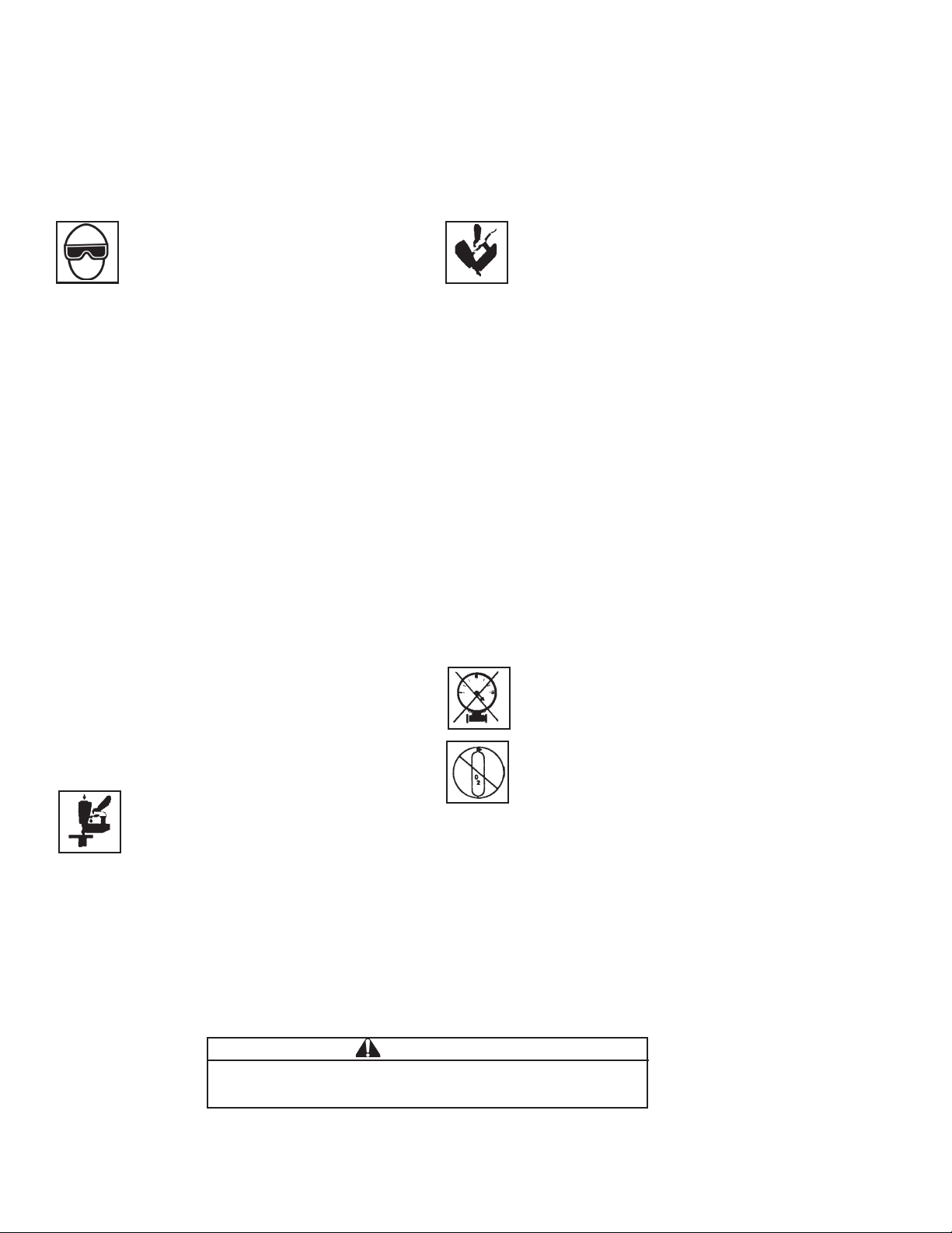
WEAR EYE AND HEARING PROTECTION
Always wear hearing protection and eye protection devices,
including side shields when operating or working in the vicinity
of a tool.
DO NOT EXCEED MAXIMUM
RECOMMENDED AIR PRESSURE
60
120
0
60
120
0
Operate the tool using only the recommended air pressure. Do
not exceed the maximum air pressure marked on the tool. Be
sure the air pressure gauge is operating properly and check it
at least twice a day.
Never use any bottled air or gases such as
oxygen to operate the tool since they could cause
the tool to explode.
Page 11

T250S-F16
37
1
84
85
38
501680
30
31
28
34
24
26
25
37
40
57
58
59
39
60
56
55
67
87
66
63
54
68
88
41
74
69
65
75
73
70
86
72
52
76
71
42
77
43
50
51
45
44
53
79
78
81
80
46
47
46
48
49
83
82
2
3
4
5
6
7
8
9
10
11
12
16
23
Trigger
Valve
Assembly
#501988
15
13
14
17
18
19
20
21
22
27
29
33
Driver Blade
Assembly
#501987
32
35
36
Assembly Hardware System - Metric
WARNING
All parts must be periodically inspected and
replaced if worn or broken. Failure to do this can
affect the tool’s operation and present a safety
hazard.
61
64
62
11
Page 12

ACCESSORIES
.
L
ubricants
Tool Cleaner
Safety Glasses
027304 .oN traP.zo 61 liO gnitacirbuL
090912 .oN traP.zo 8 ezeerftinA htiw liO gniacirbuL
437304 .oN traP.bl1 tnacirbuL 017 xelpmehC
483912 .oN traP.sloot edolsaP lla rof renaelc laedI
382104 .oN traPraelC
Tool Case
Handy carrying case that conveniently stores your tool
879105 .oN traP .seirossecca lanoitidda rof moor htiw
© 2010, Illinois Tool Works, Inc.
P
An Illinois Tool Works Company
888 Forest Edge Drive
Vernon Hills, Illinois 60061-8117
501977-3
04/10
 Loading...