

Page 1
P
P
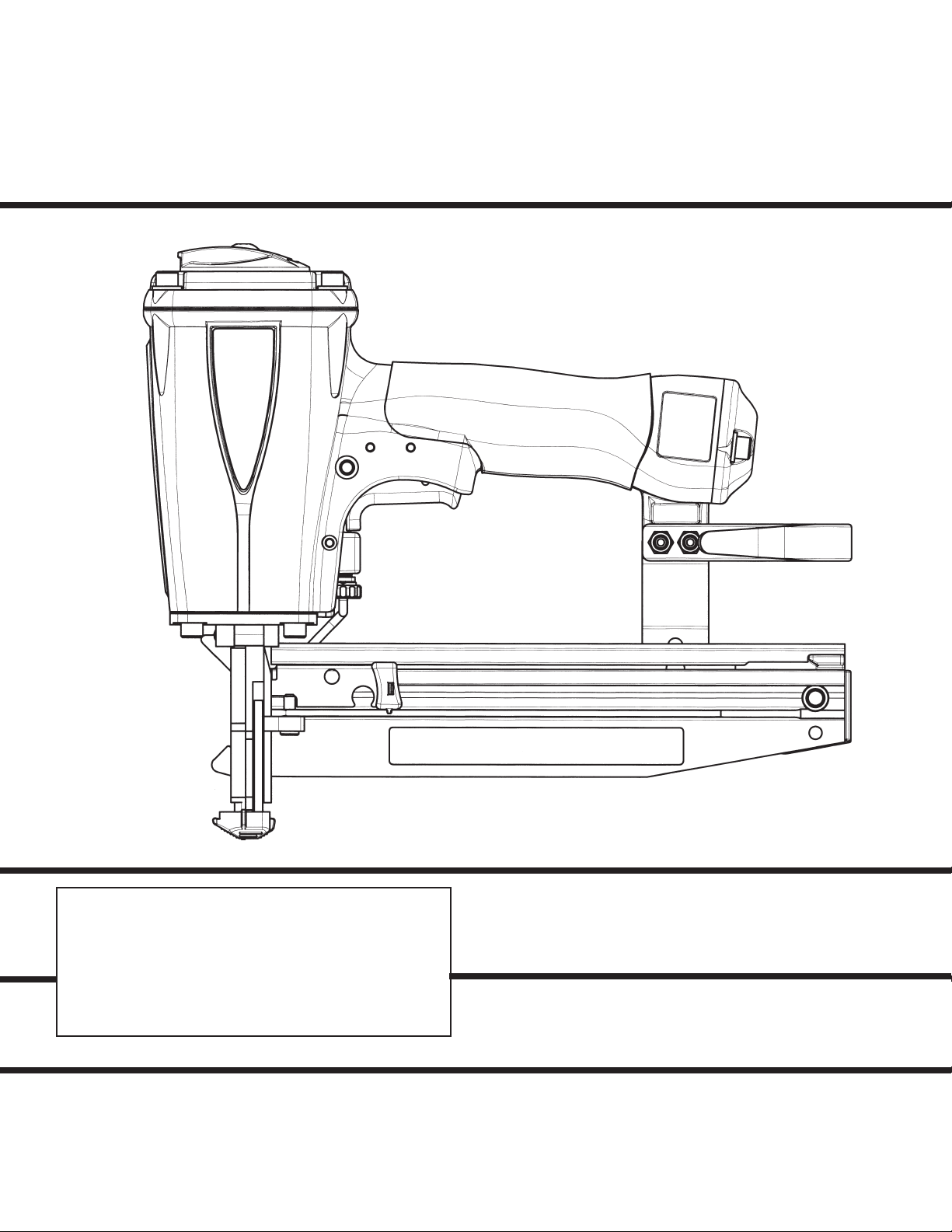
MODEL T250-F16
16 Gauge Straight
Finish Nailer
IMPORTANT!
DO NOT DESTROY
It is the customer’s responsibility to have all
operators and service personnel read and
understand this manual.
OPERATING MANUAL AND
SCHEMATIC
Page 2
INTRODUCTION
The PASLODE® T250-F16 finish nailer is a quality-built tool designed for use in residential
trim applications. This tool will deliver efficient, dependable performance when used according
to the manufactures guidelines. Please study this manual including the safety instructions to
fully understand the operation of this tool.
TOOL AND FASTENER SPECIFICATIONS ................................................... 3
SAFETY INSTRUCTIONS .............................................................................. 4
INSTRUCTIONS FOR LOADING ................................................................... 5
EXPLODED VIEW AND SPARE PARTS LIST ............................................... 6
ACCESSORIES .............................................................................................. 8
TOOL WARRANTY AND LIMITATIONS
2
Page 3

TOOL AND FASTENER SPECIFICATIONS
TOOL SPECIFICATIONS
MODEL NO. T250-F16 (Part# 500970)
HEIGHT 10”
WIDTH 3-1/8”
LENGTH 12”
WEIGHT 4lbs. 2oz.
OPERATING PRESSURE 80 to 120 p.s.i. (5.5 to 8.3 bars)
FASTENER SPECIFICATIONS
NAIL LENGTH 3/4” - 2-1/2”
SHANK DIAMETER 16 gauge
TOOL AIR FITTINGS:
This tool uses a 1/4” N.P.T. male plug. The inside diameter should be .28” (7mm)
or larger. The fitting must be capable of discharging tool air pressure when
disconnected from the air supply.
OPERATING AIR PRESSURE:
80 to120 p.s.i. (5.5 to 8.3 bars). Select the operating air pressure within this range
for best tool performance.
DO NOT EXCEED THIS RECOMMENDED OPERATING PRESSURE.
3
Page 4

SAFETY INSTRUCTIONS
SAFETY FIRST
These safety instructions provide information necessary
for safe operation of Paslode® tools. DO NOT ATTEMPT
TO OPERATE THE TOOL UNTIL YOU READ AND
UNDERSTAND ALL SAFETY PRECAUTIONS AND
MANUAL INSTRUCTIONS.
WEAR EYE AND HEARING PROTECTION
Always wear hearing and eye protection devices, that
conform to ANZI Z87.1 requirements, when operating
or working in the vicinity of a tool. As an employer you
are responsible for enforcing the use of eye protection.
Wear hard hats in environments that require their use.
THE TOOL MUST BE USED ONLY FOR THE PURPOSE FOR WHICH IT WAS DESIGNED
Do not throw the tool on the floor, strike the housing in
any way or use the tool as a hammer to knock
material into place.
NEVER ENGAGE IN HORSEPLAY WITH THE TOOL
The tool is not a toy so do not use it like one. Never
engage in horseplay with the tool or point it at yourself
or any other person, even if you think it is not loaded.
NEVER ASSUME THE TOOL IS EMPTY
Check the magazine for fasteners that may be left in the
tool. Even if you think the tool is empty or disconnected,
never point it at anyone or yourself. Unseen fasteners
could fire from the tool.
NEVER CLAMP THE TRIGGER IN A LOCKED OR
OPERATING POSITION
The trigger of the tool must never be tampered with,
disabled or clamped in a locked or operating position
since this will cause the tool to drive a fastener any time
the work contacting element depressed.
DO NOT LOAD FASTENERS WITH THE AIR LINE
CONNECTED, OR WITH THE TOOL TRIGGER OR
WORK CONTACTING ELEMENT DEPRESSED
When loading fasteners into the tool be sure you disconnect the air line and that you do not depress the trigger
or work contacting element.
OPERATE THE TOOL ONLY ON A WORKPIECE
The tool should be operated only when it is in contact
with the workpiece. Even then you should be careful
when fastening thin material or working near the edges
and corners of the workpiece since the fasteners may
drive through or away from the workpiece.
DO NOT DISABLE OR REMOVE THE WORK CONTACTING ELEMENT
This tool is equipped with a safety mechanism, called a
work contacting element, to help prevent
accidental firing. Never tamper with, disable or remove
the work contacting element. Do not use the tool unless
the work contacting element is working properly. The
tool could fire unexpectedly.
Always disconnect the tool from the air line when it
is not in use, when you leave the work area or when
moving the tool to a new location. The tool must
never be left unattended because people who are
not familiar with the tool might handle it and injure
themselves or others.
CARRY THE TOOL ONLY BY THE HANDLE
Always carry the tool by the handle only. Never carry
the tool by the air hose or with the trigger depressed
since you could drive a fastener unintentionally and
injure yourself or someone else.
DO NOT WEAKEN THE TOOL HOUSING
The tool housing is a pressure vessel and should never
be weakened by having your company’s name, area of
work or anything else stamped or engraved into its
surface.
DISCONNECT THE TOOL WHEN PERFORMING
REPAIRS AND CLEARING JAMS
Never attempt to clear a jam or repair a tool unless you
have disconnected the tool from the air line and
removed all remaining fasteners from the tool.
ALWAYS USE THE PROPER FITTING FOR THE
TOOL
Only MALE pneumatic type air connectors should be
fitted to the tool, so that high pressure air in the tool is
vented to atmosphere as soon as the air line is
disconnected.
NEVER install FEMALE quick disconnect couplings on
the tool. Female couplings will trap high pressure air in
the tool when the air line is disconnected, leaving the
tool charged and able to drive at least one fastener.
DO NOT EXCEED THE MAXIMUM RECOMMENDED
AIR PRESSURE
Operate the tool only at the recommended air pressure.
Do not exceed the maximum air pressure marked on
the tool. Be sure the air pressure gauge is
operating properly and check it at least twice a day.
Never use any bottled air or gases such as oxygen to
operate the tool since they could cause the tool to
explode.
INSPECT TOOL FOR PROPER OPERATION
Clean the tool at least daily and lubricate as required.
Never operate a dirty or malfunctioning tool.
USE ONLY PASLODE RECOMMENDED PARTS AND
FASTENERS
Use only parts and fasteners specifically designed and
recommended by Paslode for use in the tool and for
work to be done. Using unauthorized parts and
fasteners or modifying the tool in any way creates
dangerous situations. Replace all missing warning
labels---refer to tool schematic for correct placement
and part number.
DISCONNECT THE TOOL WHEN NOT IN USE
Failure to follow any of the above instructions could result in severe personal
injury to tool user and bystanders or cause damage to tool and property.
Contact your local Paslode Representative for presentation of Paslode’s Safety Awareness Program
WARNING
4
Page 5

Adjustable
Exhaust Cap
Direct exhaust where
you want it.
Avoid dust!
Powerful Motor
Drive 16 gauge finish
nails from 3/4” to
2 -1/2” offering
versatility for many
applications.
T250-F16 FEATURES & BENEFITS
Ergonomic Handle with
Sure Grip
Comfortable design and suregrip
provide more control and less
fatigue.
Reversible Belt Hook
Hang your tool on your
belt or ladder for overhead
work.
Compact
Lightweight Design
Only 4.3 lbs. and able to
get into tight spots.
Adjustable Depth of
Drive
Provides precise control
of nail depth into hard or
soft wood.
Quick Clear Nose
Easy access to possible
nail jams. (opposite side)
Narrow Long Nose
Precise placement of nails.
No-Mar Tip
With Site Lines
Prevents damage to
expensive trim. Clear line
of sight.
P
Two Finger Trigger
Provides less fatigue and
more control.
Top Load Magazine
Insert nails down into the
channel. Holds 2 strips
or 100 nails.
Ergonomic Magazine Release
Quick and easy loading.
Reload Indicator
View quickly when
nails are needed.
USE ONLY
16 GAUGE STRAIGHT
FINISH NAILS
Loading Instructions:
Step No. 1 – Pull back the magazine release.
Step No. 2 – Insert 16 gauge straight finish nails down into the magazine.
Step No. 3 – Move magazine release forward.
5
Page 6

PARTS LEGEND T250-F16, 500970
1 501043 1 T.H.S.C.S. 1/4-20 x 1/2
2 500956 1 Cap Diffuser
3 501299 6 S.H.C.S. 1/4-20 x 1
4 403582 1 Jam Nut
5 500958 1 Cap
6 402717 1 Conical Spring
7 404230 1 Retaining Ring
8 404122 1 Upper Valve Piston
9 091537 1 O-Ring, Main Valve Assembly
*
10 404054 1 Seal, Main Valve
11 404056 1 Lower Valve Piston
12 090927 1 O-Ring, Main Valve
*
13 092775 1 O-Ring, Main Valve
*
14 092773 1 O-Ring, Main Valve
*
15 404256 2 O-Ring,Valve Post, End Plug
*
16 500954 1 Post Main Valve
17 015660 1 S.H.C.S. 10-24 x 1/2
18 501169 1 Piston
19 405430 1 O-Ring, Piston
*
20 404274 1 Washer
21 403594 1 Driver Blade
*
22 402725 1 Seal, Sleeve
*
23 405243 1 Flange, Sleeve
24 500952 1 Sleeve
25 402728 1 O Ring, Sleeve
*
26 091966 1 O Ring, Sleeve
*
27 500369 1 O-Ring, Sleeve
*
28 500975 1 Gasket, Cap
*
29 501140 1 Logo, Housing L
30 500957 1 Housing
31 501141 1 Logo, Housing R
32 402708 1 Gasket, Nose Flange
33 500950 1 Bumper
*
34 403705 1 Seal, Driver Blade
35 402706 1 Flange
36 091545 4 S.H.C.S. 1/4-20 x 7/8
37 402629 1 Hardened Washer
38 405076 1 Spring
39 403716 3 S.H.C.S. 10-32 X 5/16
40 403712 1 Front Guide Latch Assembly
41 501133 1 Rail Bracket Assembly
42 401988 1 Spring, Front Guide Latch
* Denotes Normal Wear Items.
** Make sure Warning Label (500458) is properly affixed.
Replace if necessary.
Label available at no charge through the Service Parts Dept.
▲ Apply Loctite 242 (Blue) Part No. 093500.
Denotes New Change
➔
*
*
43 403812 2 Flat Washer
44 004238 2 Lock Washer
45 004224 2 S.H.C.S. - 10-32 x 3/8
46 500458 1 Warning Label
47 500772 1 Spring, W.C.E.
48 501143 1 Intermediate W.C.E.
49 500766 1 Guide Block
50 071297 1 Roll Pin 1/8 x 1-1/8
51 500840 1 W.C.E. Assembly
52 404180 1 Probe Tip
53 404698 2 Roll Pin Assembly
54 402730 1 Pivot Pin, front Guide
55 403592 1 Front Guide
56 403591 1 Back Plate
57 501023 1 Grip Handle
58 080326 2 S.H.C.S. 10-32 x 1
60 500963 1 End Plug
61 500955 1 Belt Hook
62 092037 4 Lock Nut 10-32
63 097748 1 Spring, Valve Pin
64 097746 1 Valve Pin
65 092174 1 O-Ring, Valve Body
66 026133 2 Roll Pin, 1/8 x 1
67 401958 1 Valve Body
68 402668 1 Retaining Washer
69 501008 1 Lever, Bump Trigger
70 501010 1 Bump Trigger
71 501009 1 Roll Pin
72 402669 1 Pin, Trigger
73 500972 1 Rail Cover Assembly
74 403713 1 Retaining Ring
75 500968 1 Rail Assembly
76 009397 2 S.H.C.S. 10-24 x 1/2
77 501142 1 Nameplate
78 091536 1 Spring, Follower Latch Pin
79 403711 1 Latch Pin, Follower
80 094295 1 O-Ring
81 403710 1 Roller, Negator
82 403708 1 Negator Assembly
83 403715 1 Follower Assembly
84 501139 1 Follower Tab
85 500973 2 Wear Strip
86 501039 1 Sequential Trigger
SAFETY INSTRUCTIONS
WEAR EYE AND HEARING PROTECTION
Always wear hearing protection and eye protection
devices, including side shields when operating or
working in the vicinity of a tool.
DO NOT EXCEED MAXIMUM
RECOMMENDED AIR PRESSURE
Operate the tool using only the recommended air
pressure. Do not exceed the maximum air pressure
marked on the tool. Be sure the air pressure gauge is
operating properly and check it at least twice a day.
Never use any bottled air or gases such as oxygen to operate the tool since they could cause the
tool to explode.
6
Page 7

1
2
22
T250-F16
500970
25
3
23
Cap Assembly
#500974
Main Valve
Assembly #404188
9
12
13
14
15
Piston Assembly
#501583
19
26
5
27
24
57
3
6
28
58
15
60
29
7
62
61
51
63
4
20
17
18
21
16
8
10
11
39
47
37
38
49
40
30
44
45
32
35
41
31
33
34
42
43
46
36
64
65
67
68
73
75
66
74
72
86
OPTIONAL:
69
70
80
81
Bump
Trigger
Assembly
#501048
85
82
71
83
52
51
48
53
50
55
54
39
76
78
79
77
84
WARNING
56
7
All parts must be periodically inspected and replaced if
worn or broken. Failure to do this can affect the tool’s
operation and present a safety hazard.
Page 8

ACCESSORIES
Back Plate Insert
This insert accommodates 1 1/4” and shorter finish nails.
Also prevents nails from tumbling and jamming. Part No. 1X1210
Lubricants and Loctite
Loctite 242 (Blue) Part No. 093500
Lubricating Oil 16 oz. Part No. 403720
Lubricaing Oil with Anitfreeze 8 oz. Part No. 219090
Chemplex 710 Lubricant 1lb. Part No. 403734
Degreaser Cleaner
Ideal cleaner for all Paslode tools. Part No. 219086
Safety Glasses
Clear Part No. 402510
Tool Case
Handy carrying case that conveniently stores your tool
with room for additional accessories. Part No. 501152
3-Strip Capacity Magazine Assembly
Offers the flexibility to increase the tool’s magazine
capacity to 150 nails. Part No. 219271
➔ 1/4” Swivel Air Fitting Part No. 501506
PRINTED IN U.S.A.
© 2007, Illinois Tool Works, Inc.
P
An Illinois Tool Works Company
888 Forest Edge Drive
Vernon Hills, Illinois 60061-3105
405646-8
11/05
 Loading...