

Page 1
P
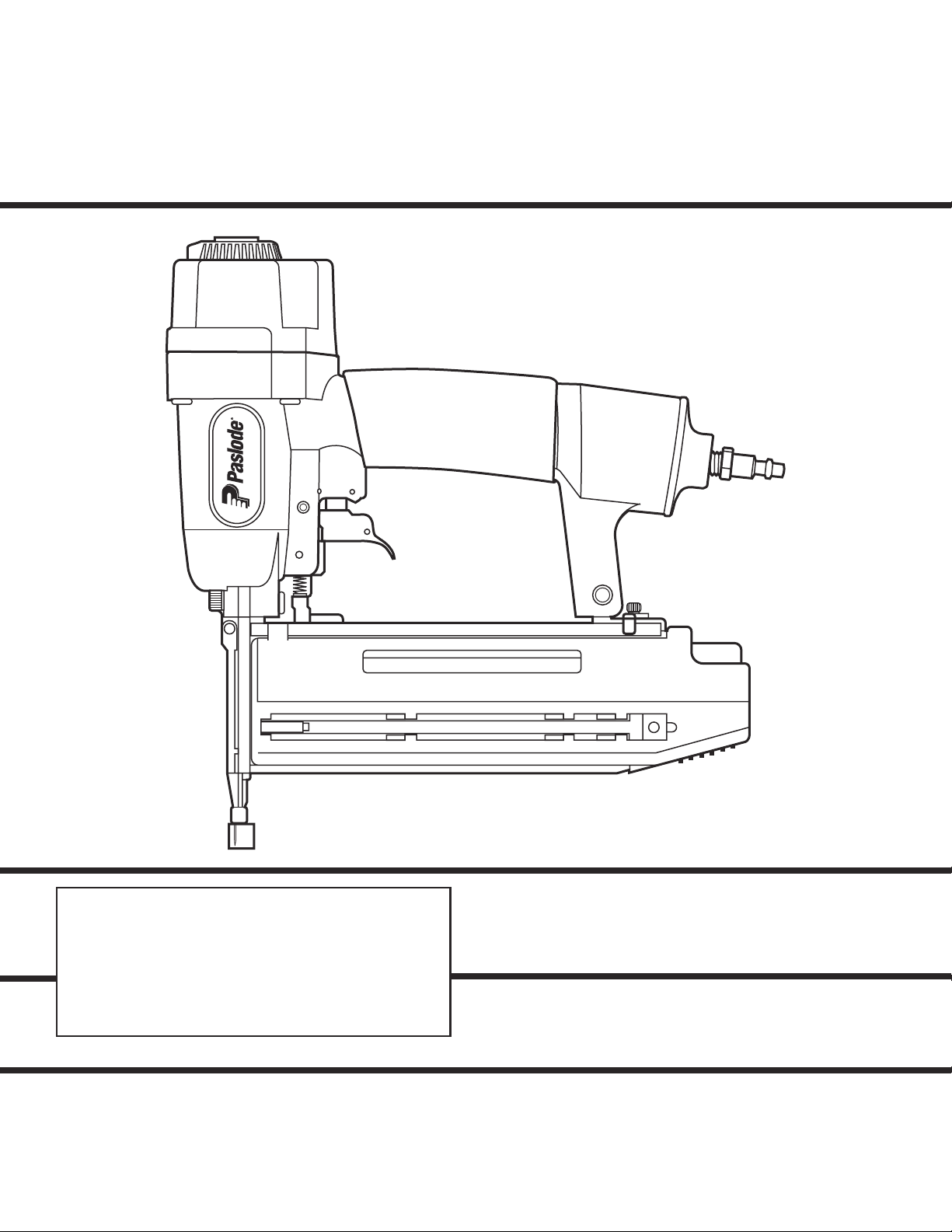
MODEL T200-F18
MODEL T125-F18
Finish Nailers
IMPORTANT!
DO NOT DESTROY
It is the customerʼs responsibility to have all
operators and service personnel read and
understand this manual.
OPERATING MANUAL AND
SCHEMATIC
Page 2
INTRODUCTION
The PASLODE® T200-F18 and T125-F18 finish nailers are quality-built tools designed for use in
residential trim applications. These tools will deliver efficient, dependable performance when used
according to the manufactures guidelines. Please study this manual including the safety
instructions to fully understand the operation of these tools.
TOOL AND FASTENER SPECIFICATIONS ................................................... 3
SAFETY INSTRUCTIONS .............................................................................. 4
INSTRUCTIONS FOR LOADING ................................................................... 5
EXPLODED VIEW AND SPARE PARTS LIST ............................................... 6
ACCESSORIES .............................................................................................. 8
TOOL WARRANTY AND LIMITATIONS
2
Page 3

TOOL AND FASTENER SPECIFICATIONS
MODEL NO. T200-F18 (Part# 500959) T125-F18 (Part#501161)
HEIGHT 9-3/4"
WIDTH 2-3/8"
LENGTH 9-3/4"
WEIGHT 2.1lbs.
NAIL LENGTH 5/8" - 2" 5/8” - 1-1/4”
SHANK DIAMETER 18 gauge
OPERATING PRESSURE 70 to 100 p.s.i.
7-1/2”
2-3/8”
9-2/3”
1.75 lbs.
TOOL AIR FITTINGS:
This tool uses a 1/4” N.P.T. male plug. The inside diameter should be .28” (7mm)
or larger. The fitting must be capable of discharging tool air pressure when
disconnected from the air supply.
OPERA TING AIR PRESSURE:
70 to100 p.s.i. Select the operating air pressure within this range for best tool
performance.
DO NOT EXCEED THIS RECOMMENDED OPERATING PRESSURE.
3
Page 4

SAFETY INSTRUCTIONS
SAFETY FIRST
These safety instructions provide information necessary
for safe operation of Paslode® tools. DO NOT ATTEMPT
TO OPERATE THE TOOL UNTIL YOU READ AND
UNDERSTAND ALL SAFETY PRECAUTIONS AND
MANUAL INSTRUCTIONS.
WEAR EYE AND HEARING PROTECTION
Always wear hearing and eye protection devices, that
conform to ANZI Z87.1 requirements, when operating or
working in the vicinity of a tool. As an employer you are
responsible for enforcing the use of eye protection.
Wear hard hats in environments that require their use.
THE TOOL MUST BE USED ONLY FOR THE PURPOSE FOR WHICH IT WAS DESIGNED
Do not throw the tool on the floor, strike the housing in
any way or use the tool as a hammer to knock
material into place.
NEVER ENGAGE IN HORSEPLAY WITH THE TOOL
The tool is not a toy so do not use it like one. Never
engage in horseplay with the tool or point it at yourself
or any other person, even if you think it is not loaded.
NEVER ASSUME THE TOOL IS EMPTY
Check the magazine for fasteners that may be left in the
tool. Even if you think the tool is empty or disconnected,
never point it at anyone or yourself. Unseen fasteners
could fire from the tool.
NEVER CLAMP THE TRIGGER IN A LOCKED OR
OPERATING POSITION
The trigger of the tool must never be tampered with,
disabled or clamped in a locked or operating position
since this will cause the tool to drive a fastener any time
the work contacting element depressed.
DO NOT LOAD FASTENERS WITH THE AIR LINE
CONNECTED, OR WITH THE TOOL TRIGGER OR
WORK CONTACTING ELEMENT DEPRESSED
When loading fasteners into the tool be sure you
disconnect the air line and that you do not depress the
trigger or work contacting element.
OPERATE THE TOOL ONLY ON A WORKPIECE
The tool should be operated only when it is in contact
with the workpiece. Even then you should be careful
when fastening thin material or working near the edges
and corners of the workpiece since the fasteners may
drive through or away from the workpiece.
DISCONNECT THE TOOL WHEN NOT IN USE
Always disconnect the tool from the air line when it is
not in use, when you leave the work area or when
moving the tool to a new location. The tool should
never be left unattended because people who are
not familiar with the tool might handle it and injure
themselves or others.
CARRY THE TOOL ONLY BY THE HANDLE
Always carry the tool by the handle only. Never carry
the tool by the air hose or with the trigger depressed
since you could drive a fastener unintentionally and
injure yourself or someone else.
DO NOT WEAKEN THE TOOL HOUSING
The tool housing is a pressure vessel and should never
be weakened by having your company’s name, area
of work or anything else stamped or engraved into its
surface.
DISCONNECT THE TOOL WHEN PERFORMING
REPAIRS AND CLEARING JAMS
Never attempt to clear a jam or repair a tool unless you
have disconnected the tool from the air line and
removed all remaining fasteners from the tool.
ALWAYS USE THE PROPER FITTING FOR THE
TOOL
Only MALE pneumatic type air connectors should be
fitted to the tool, so that high pressure air in the tool is
vented to atmosphere as soon as the air line is
disconnected.
NEVER install FEMALE quick disconnect couplings on
the tool. Female couplings will trap high pressure air
in the tool when the air line is disconnected, leaving
the tool charged and able to drive at least one fastener.
DO NOT EXCEED THE MAXIMUM RECOMMENDED
AIR PRESSURE
Operate the tool only at the recommended air pressure. Do not exceed the maximum air pressure marked
on the tool. Be sure the air pressure gauge is
operating properly and check it at least twice a day.
Never use any bottled air or gases such as oxygen to
operate the tool since they could cause the tool to
explode.
INSPECT TOOL FOR PROPER OPERATION
Clean the tool at least daily and lubricate as required.
Never operate a dirty or malfunctioning tool.
DO NOT DISABLE OR REMOVE THE WORK CONTACTING ELEMENT
This tool is equipped with a safety mechanism, called a
work contacting element, to help prevent
accidental firing. Never tamper with, disable or remove
the work contacting element. Do not use the tool unless
the work contacting element is working properly. The
tool could fire unexpectedly.
WARNING
Failure to follow any of the above instructions could result in severe personal
injury to tool user and bystanders or cause damage to tool and property.
Contact your local Paslode Representative for presentation of Paslode’s Safety Awareness Program
USE ONL Y P ASLODE RECOMMENDED P ARTS AND
FASTENERS
Use only parts and fasteners specifically designed and
recommended by Paslode for use in the tool and for
work to be done. Using unauthorized parts and
fasteners or modifying the tool in any way creates
dangerous situations. Replace all missing warning
labels---refer to tool schematic for correct placement
and part number.
4
Page 5

INSTRUCTIONS FOR LOADING
Step No. 1 – Grasp the finish nailer firmly with one hand and press the orange magazine release button at the
rear of the magazine and pull the magazine back towards you.
Step No. 2 – Insert the strip of 18 gauge finish nails with the point of the fastener facing down and place the point
of the fastener into the bottom of the magazine channel. Placing fasteners on the top of the magazine will cause
jamming.
Step No. 3 – Push the magazine firmly towards the front of the tool until it locks in place. The tool is now ready for
use.
5
Page 6

PARTS LEGEND T200-F18, 500959
T125-F18, 501161
1 500976 1 Deflector
2 500977 4 Bolt w/ Flat Washer
3 500978 1 Hex Soc. Hd. Screw
4 500979 1 Cap (T200)
5 500980 1 Seal
6 500981 1 Compression Spring
7 500982 1 O-Ring
*
8 500983 1 O-Ring
9 500984 1 Head Valve Piston
*
10 500985 1 O-Ring
11 500986 1 Gasket, Cap
12 500987 1 Piston Ring
*
13 500988 1 O-Ring
14 500989 1 Piston Assembly (T200)
*
15 500990 1 Cylinder (T200)
16 500991 1 O-Ring
17 500992 1 Cylinder Ring
*
18 500993 1 Bumper
19 500994 1 Driver Guide (T200)
20 500995 1 O-Ring
21 500996 1 Trigger Valve Head
22 500997 1 Spring
23 500998 1 Plunger
24 500999 1 O-Ring
➔
25 501082 1 O-Ring
26 501083 1 Plunger Cap
27 501084 2 Roll Pin
28 501085
➔
29 501086
➔
➔
30 501087
31 501088 1 Trigger Pivot Pin
32 501089 2 Urethane Retainer
33 501090 1 Housing Assembly
34 501091 1 Air Plug
35 501092 1 Dust Cover
36 501093 2 Bolt Assembly (T200)
37 501094 1 Front Cover
38 501095 1 Front Guide (T200)
39 501096 1 Fixed Pin
40 501097 1 Hex Soc Hd Bolt
41 501098 1 Back Plate (T200)
42 501099 1 Fixed Magazine (T200)
43 501100 1 Flat Bar (T200)
44 501101 2 Bolt Assembly
501170 1 Cap (T125)
501171 1 Piston Assembly (T125)
501172 1 Cylinder (T125)
501173 1 Driver Guide (T125)
1 Trigger Lever
1 Trigger
1 Roll Pin
501176 2 Bolt Assembly (T125)
501177 1 Front Guide (T125)
501178 1 Back Plate (T125)
501179 1 Fixed Magazine (T125)
501180 1 Flat Bar (T125)
* Denotes Normal Wear Items.
** Make sure Warning Label (500492 or 501197) is properly affixed.
Replace if necessary.
Label available at no charge through the Service Parts Dept.
▲ Apply Loctite 242 (Blue) Part No. 093500.
➔ Denotes Change
45 501102 1 Stop
46 501103 1 Bracket (T200)
47 501104 1 Follower (T200)
48 501105 1 Shaft
49 501106 1 Follower Spring (T200)
50 501107 1 Moveable Magazine (T200)
51 501108 1 Spring Cover
52 501109 1 Latch (T200)
53 501110 1 Latch Pin (T200)
54 501111 1 Lock Spring
55 501112 1 Latch Cover (T200)
56 501113 2 Tap Bolt
57 501191 1 W.C.E. Guide
58 501115 1 Roll Pin
59 501192 1 W.C.E. Spring
60 501193 1 Upper W.C.E.
61 501174 1 E-Ring
62 501175 1 Interm. W.C.E. (T200)
63 501120 1 Lower W.C.E. (T200)
64 501121 1 Protective Tip
65 501122 1 Anchor Block
66 501123 1 Magazine Spacer
67 501124 1 Lock Spring
68 501125 1 Latch
69 501126 1 Flat Washer
70 501127 1 Hex Soc Hd Bolt
71 501128 1 Bolt Assembly
72 501188 1 W.C.E. Stop
73 501130 1 Hex Soc Hd Bolt
74 501131 1 Lock Nut
75 500492 1 Warning Label (T200)
76 501134 1 Magazine Label (T200)
77 501135 2 Housing Label
78 501189 1 Hex Socket Button Hd Bolt
79 501190 1 Stop
80 501194 1 Adjuster
81 501271 1 O-Ring
82 501272 1 End Cap
83 501273 1 O-Ring
➔
84 219260 1 Insert, Long
85 219261 1 Insert, Short
➔
86 501387 1 Trigger Spring
➔
501187 1 Bracket (T125)
501181 1 Follower (T125)
501183 1 Follower Spring (T125)
501182 1 Moveable Magazine (T125)
501184 1 Latch (T125)
501185 1 Latch Pin (T125)
501186 1 Latch Cover (T125)
501195 1 Interm. W.C.E. (T125)
501196 1 Lower W.C.E. (T125)
501197 1 Warning Label (T125)
501198 1 Magazine Label (T125)
R
55
50
F/MFCS - NOITPMUSNOC RIA ENETSA
0.046
45
40
35
0.032
30
0.025
25
6
20
0.022
70 80 90 100
0.039
0.029
0.026
AIR PRESSURE - PSIG
T200-F18
T125-F18
0.033
Page 7

84
82
83
T200-F18
500959
T125-F18
501161
86
77
75
85
81
219254
51
55
76
WARNING
All parts must be periodically inspected and replaced if
worn or broken. Failure to do this can affect the toolʼs
operation and present a safety hazard.
7
Page 8

ACCESSORIES
Safety Glasses
Lubricants and Loctite
015204 .oN traPraelC
005390 .oN traP)eulB( 242 etitcoL
027304 .oN traP.zo 61 liO gnitacirbuL
090912 .oN traP.zo 8 ezeerftinA htiw liO gnitacirbuL
437304 .oN traP.bl1 tnacirbuL 017 xelpmehC
Degreaser Cleaner
Sequential Operating Kit
This special attachment is designed for sequential operation
(stops “contact” firing). The operator must depress and hold the
work contacting element against the work surface before pulling
the trigger. This sequence must be repeated each time the tool
rd
Contact Trip Trigger
680912 .oN traP.sloot edolsaP lla rof renaelc laedI
452912 .oN traP.renetsaf a sevi
562912 .oN traP.gnirif ”ecnuob“ ro evisseccus rof swolla tik sihT
PRINTED IN U.S.A.
© 2008, Illinois Tool Works, Inc.
P
An Illinois Tool Works Company
888 Forest Edge Drive
Vernon Hills, Illinois 60061-3105
405645-6
10/08
 Loading...