

Page 1
P
Part No. 515500
MODEL
T250S-F16P
16 Gauge Straight
Finish Nailer
IMPORTANT!
DO NOT DESTROY
It is the customerʼs responsibility to have all
operators and service personnel read and
understand this manual.
P
RINTED IN TAIWAN
© 2018, Illinois Tool Works Inc.
219495-2
08/18
OPERATING MANUAL AND
TOOL SCHEMATIC
Page 2

INTRODUCTION
The PASLODE® T250S-F16P
finish nailer is a quality-built tool designed for use in residential
trim applications. This tool will deliver efficient, dependable performance when used according
to the manufactures guidelines. Please study this manual including the safety instructions to
fully understand the operation of this tool.
TOOL AND FASTENER SPECIFICATIONS ....................................................... 3
SAFETY INSTRUCTIONS ...................................................................................4
TOOL OPERATION ..............................................................................................5
EXPLODED VIEW AND SPARE PARTS LIST ..............................................10-11
ACCESSORIES ..................................................................................................12
TOOL WARRANTY AND LIMITATIONS
Paslode warrants that newly purchased power
fastening tools, parts and accessories will be free
from defects in material and workmanship for the
period shown below, after the date of delivery to
the original user.
ONE-YEAR FULL WARRANTY
A one-year warranty will apply to all parts, except
those which are specifically covered by an extended
warranty.
FIVE-YEAR EXTENDED LIMITED WARRANTY
A
five-year warranty will apply to all housing and cap
assembly castings.
WARRANTY STATEMENT
This warranty is limited to tools sold and service requested
in the United States. To obtain information on warranty
service in the United States, refer to the Service Center
listing that was provided with your tool.
Paslode's sole liability hereunder will be to replace any part
or accessory which proves to be defective within the specific
time period. Any replacement part or accessory provided in
accordance with this warranty will carry a warranty for the
balance of the period of warranty applicable to the part it
replaces. This warranty does not apply to part replacement
required due to normal wear.
This warranty is void as to any tool which has been subjected
to misuse, abuse, accidental or intentional damage, use with
fasteners,not meeting
improperly maintained,
Paslode replacement parts,
which, in Paslode's opinion,
way that affects or detracts
Paslode specification, size, or quality,
repaired with other than genuine
damaged in transit or handling, or
has been altered or repaired in a
from the performance of the tool.
Paslode reserves the right to change specifications, equipment, or
designs at any time without notice and without incurring obligation.
PASLODE MAKES NO WARRANTY, EXPRESSED OR
IMPLIED, RELATING TO MERCHANTABILITY, FITNESS, OR
OTHERWISE, EXCEPT AS STATED ABOVE, and Paslode's
liability AS STATED ABOVE AND AS ASSUMED ABOVE is
in lieu of all other warranties arising out of, or in connection
with, the use and performance of the tool, except to the extent
other wise provided by applicable law. PASLODE SHALL IN
NO EVENT BE LIABLE FOR ANY DIRECT, INDIRECT, OR
CONSEQUENTIAL DAMAGES, INCLUDING, BUT NOT
LIMITED TO, DAMAGES WHICH MAY ARISE FROM LOSS
OF ANTICIPATED PROFITS OR PRODUCTION, SPOILAGE
OF MATERIALS, INCREASED COST OF OPERATION, OR
OTHERWISE.
2
Page 3

TOOL AND FASTENER SPECIFICATIONS
TOOL SPECIFICATIONS
MODEL NO. T250S-F16P (Part# 515500)
HEIGHT 11.6"
WIDTH 2.9"
LENGTH 12.3"
WEIGHT 3.9lbs.
OPERATING PRESSURE 80 to 120 p.s.i. (5.5 to 8.3 bars)
FASTENER SPECIFICATIONS
NAIL LENGTH 1" - 2-½"
SHANK DIAMETER 16 gauge
TOOL AIR FITTINGS:
This tool uses a 1/4” N.P.T. male plug. The inside diameter should be .28” (7mm)
or larger. The fitting must be capable of discharging tool air pressure when
disconnected from the air supply.
OPERATING AIR PRESSURE:
80 to 120 p.s.i. (5.5 to 8.3 bars). Select the operating air pressure within this range
for best tool performance.
DO NOT EXCEED THIS RECOMMENDED OPERATING PRESSURE.
3
Page 4
SAFETY INSTRUCTIONS
SAFETY FIRST
These safety instructions provide information necessary
for safe operation of Paslode
TO OPERATE THE TOOL UNTIL YOU READ AND
UNDERSTAND ALL SAFETY PRECAUTIONS AND
MANUAL INSTRUCTIONS.
WEAR EYE AND HEARING PROTECTION
Always wear hearing and eye protection devices, that
conform to ANSI Z87.1 requirements, when operating
or working in the vicinity of a tool. As an employer you
are responsible for enforcing the use of eye protection.
Wear hard hats in environments that require their use.
THE TOOL MUST BE USED ONLY FOR THE PURPOSE FOR WHICH IT WAS DESIGNED
Do not throw the tool on the floor, strike the housing in
any way or use the tool as a hammer to knock material
into place.
NEVER ENGAGE IN HORSEPLAY WITH THE TOOL
The tool is not a toy so do not use it like one. Never
engage in horseplay with the tool or point it at yourself
or any other person, even if you think it is not loaded.
NEVER ASSUME THE TOOL IS EMPTY
Check the magazine for fasteners that may be left in the
tool. Even if you think the tool is empty or disconnected,
never point it at anyone or yourself. Unseen fasteners
could fire from the tool.
NEVER CLAMP THE TRIGGER IN A LOCKED OR
OPERATING POSITION
The trigger of the tool must never be tampered with,
disabled or clamped in a locked or operating position
since this will cause the tool to drive a fastener any time
the work contacting element depressed.
DO NOT LOAD FASTENERS WITH THE AIR LINE
CONNECTED, OR WITH THE TOOL TRIGGER OR
WORK CONTACTING ELEMENT DEPRESSED
When loading fasteners into the tool be sure you
disconnect the air line and that you do not depress
the trigger or work contacting element.
OPERATE THE TOOL ONLY ON A WORKPIECE
The tool should be operated only when it is in contact
with the workpiece. Even then you should be careful
when fastening thin material or working near the edges
and corners of the workpiece since the fasteners may
drive through or away from the workpiece.
DO NOT DISABLE OR REMOVE THE WORK
CONTACTING ELEMENT
This tool is equipped with a safety mechanism, called a
work contacting element, to help prevent accidental
firing. Never tamper with, disable or remove the work
contacting element. Do not use the tool unless the work
contacting element is working properly. The tool could
fire unexpectedly.
®
tools.
DO NOT ATTEMPT
DISCONNECT THE TOOL WHEN NOT IN USE
Always disconnect the tool from the air line when it
is not in use, when you leave the work area or when
moving the tool to a new location. The tool must
never be left unattended because people who are
not familiar with the tool might handle it and injure
themselves or others.
CARRY THE TOOL ONLY BY THE HANDLE
Always carry the tool by the handle only. Never carry
the tool by the air hose or with the trigger depressed
since you could drive a fastener unintentionally and
injure yourself or someone else.
DO NOT WEAKEN THE TOOL HOUSING
The tool housing is a pressure vessel and should never
be weakened by having your companyʼs name, area of
work or anything else stamped or engraved into its
surface.
DISCONNECT THE TOOL WHEN PERFORMING
REPAIRS AND CLEARING JAMS
Never attempt to clear a jam or repair a tool unless you
have disconnected the tool from the air line and removed
all remaining fasteners from the tool.
ALWAYS USE THE PROPER FITTING FOR THE
TOOL
Only MALE pneumatic type air connectors should be
fitted to the tool, so that high pressure air in the tool is
vented to atmosphere as soon as the air line is disconnected.
NEVER install FEMALE quick disconnect couplings on
the tool. Female couplings will trap high pressure air in
the tool when the air line is disconnected, leaving the
tool charged and able to drive at least one fastener.
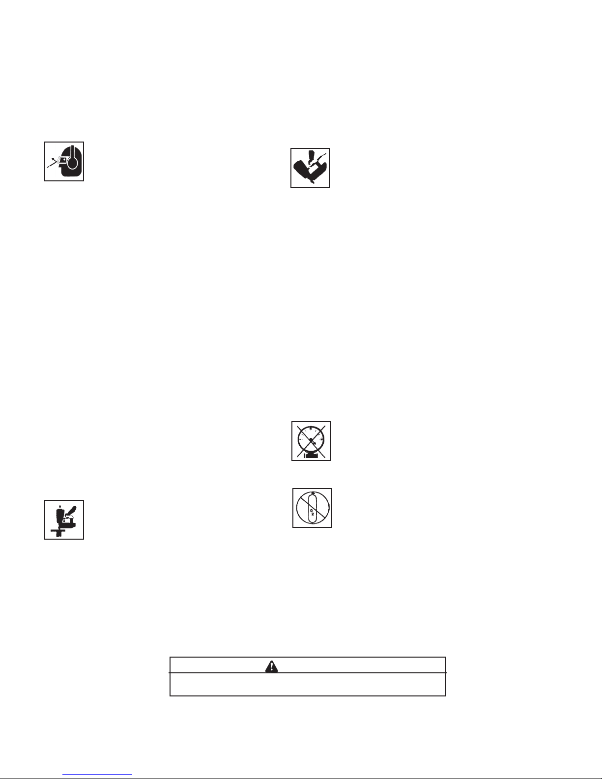
DO NOT EXCEED THE MAXIMUM RECOMMENDED
AIR PRESSURE
Do not exceed the maximum air
the tool. Be sure the air pressure gauge is operating
properly and check it at least twice a day.
Never use any bottled air or gases such as oxygen to
operate the tool since they could cause the tool to
explode. Do not operate in explosive atmospheres.
INSPECT TOOL FOR PROPER OPERATION
USE ONLY PASLODE RECOMMENDED PARTS AND
FASTENERS
Use only parts and fasteners specifically designed and
recommended by Paslode for use in the tool and for
work to be done. Using unauthorized parts and fasteners
or modifying the tool in any way creates dangerous
situations. Replace all missing warning labels. Refer
to tool schematic for correct placement and part number.
pressure marked on
.erusserp ria dednemmocer eht ta ylno loot eht etarepO
Failure to follow any of the above instructions could result in severe personal
injury to tool user and bystanders or cause damage to tool and property.
Contact your local Paslode Representative for presentation of Paslodeʼs Safety Awareness Program
WARNING
4
Page 5
TOOL OPERATION
–
Fasteners
T
he Paslode T250S-F16P Finish Nailer drives
Paslode® 16 gauge fasteners designed to be used
with the tool. The use of fasteners that do not meet
Paslode standards could cause tool damage and
will void all warranty claims.
Loading Fasteners
STEP 1: Align the heads of the Paslode 16 ga.Finish
nails to the brad channel in the rear of the magazine
and insert one or two strips. Push the nails strips
forward.
STEP 2: Next,
magazine
fasteners.
push the nails forward into the nose of the tool.
pull the follower toward the rear of the
until the follower passes the last strip of
Release the follower and let the follower
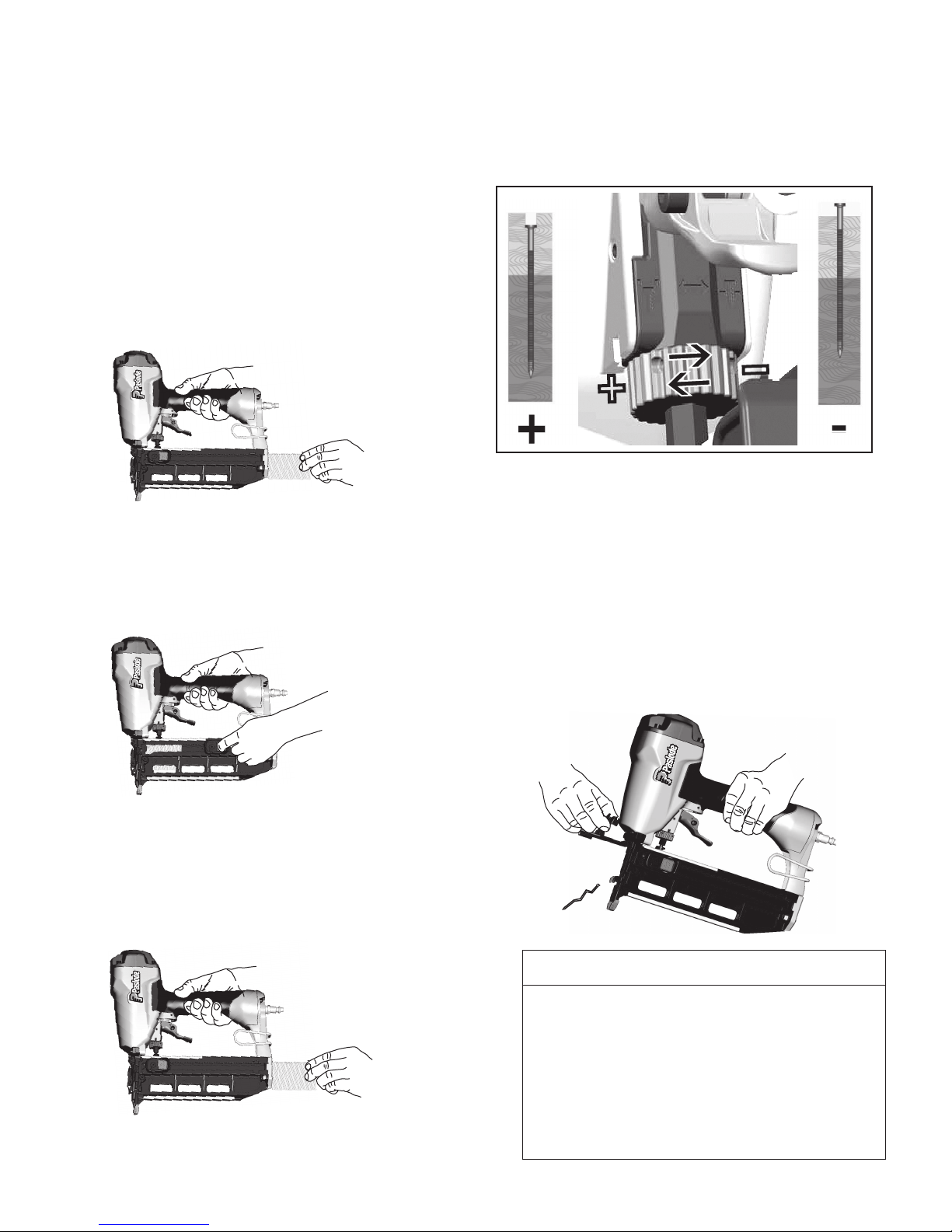
Depth of Drive Adjustment
Disconnect the air supply.
The depth of drive adjustment is done by turning the
adjustment wheel located below the trigger.
–
Clearing a Jam
An occasional problem you may encounter is a jammed
fastener. Because of the unique design of the Paslode
Finish Nailer, clearing a jammed fastener is easy:
1. Disconnect the air supply.
2. Pull the latch, releasing front guide. Pivot front guide
forward.
3. Clear jam, and push driver blade back up to its normal
position.
4. Close front guide and latch it. Check that work
contacting element moves freely.
+
When the follower reaches the reload area, marked
on the side of the magazine, you may insert a new
strip of nails. When the follower arrow reaches the
lockout area the tool automatically locks the tool to
prevent the tool from operating. To unlock the tool,
simply reload another strip of nails.
Lockout Feature
The purpose of this feature is to prevent needless
blank cycling, which could mar woods and damage
tool components.
magazine when the follower reaches the lockout
area. When changing fastener length or loading
at the beginning of the work day, you should inspect
the magazine and nose for any fasteners left in the
These nails will not be
tool.
the nose of the tool.
5
Ten (10) nails will be left in the
visible unless you open
Page 6
TOOL OPERATION
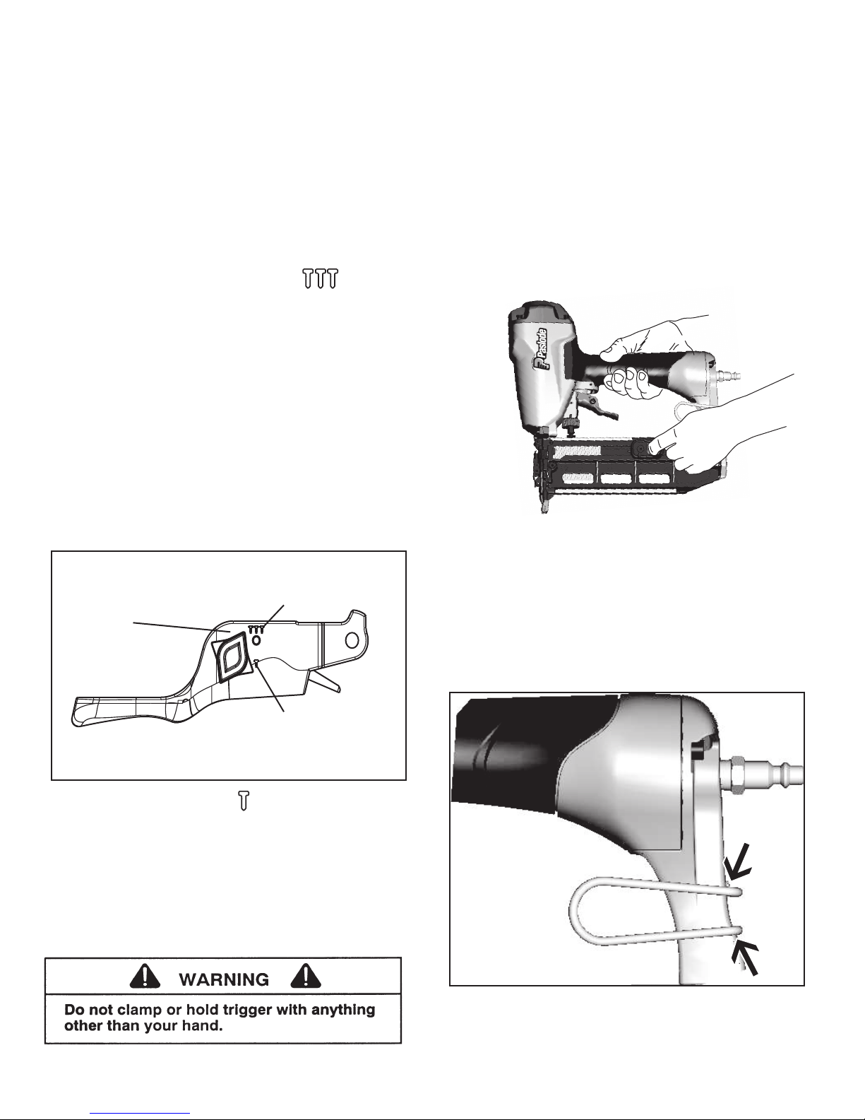
Trigger Methods:
The Paslode T250S-F16P Finish Nailer has a triggering
system than can be switched from sequential to contact
trip. To switch the trigger, press in the round button
on the left side of the trigger and rotate the right side
of the button to the desired triggering method. The TTT
indicates contact trip and the T indicates sequential
operation.
Successive (Bounce) Driving -
Grasp the handle firmly.
Squeeze the trigger and move the tool along the workpiece with a bouncing motion, depressing the work contacting element at the points where you want to drive a
fastener.
Keep the trigger depressed and continue to bounce the
work contacing element against the workpiece, positioning the tool above as carefully as possible.
When the desired number of fasteners have been
driven, release the tool trigger to avoid unintentional
fastener discharge.
Unload Nails:
To unload nails, simply pull the follower to the rear of the
magazine and press the center lock button on the follower.
The lock will move the follower out of the way and allow
nails to slide past the follower and out of the rear of the
magazine. To release the lock simply pull the follower back
and the lock button will release and allow the follower to
move forward.
Successive (Bounce)
Driving
Trigger select
indicator
Sequential
Operation
Sequential Operation -
The sequential setting T prevents succesive or "bounce"
driving.
Depress the work contacting element and hold it
against the work surface before pulling the trigger.
After each fastener is driven, completely release the
trigger and lift the tool from the work surface.
Reversible Belt Hook:
The belt hook can be changed from the left hand side of the
tool to the right hand side. To change the position, squeeze
the base of the belt hook and remove it from the tool and tool
and position it on the desired side.
6
Page 7
MAINTENANCE
Paslode® tools are built for ease of maintenance. A few
simple details will assure trouble-free operation and long
tool life. Anyone who uses or maintains the tool must read
the safety and maintenance instructions. Study the schematic drawing before starting any repairs on the tool.
Air-operated tools must be inspected periodically, and worn
or broken parts must be replaced to keep the tool operating
safely and efficiently. Also the items on the maintenance
chart must be checked often.
Cold Weather Care
When temperatures are below freezing, tools should be
kept warm by any convenient, safe method. If this is not
possible, the following procedure should be used to warm
up the tools.
❑ Reduce the regulated air pressure to 30 psi.
❑ Remove all fasteners from the tool.
❑
Collect an air line and blank fire the tool. The reduced
air pressure will be enough to free-fire the tool. Slow speed
operation tends to warm up the moving parts. Slowing up
the piston helps the bumper and the O-rings to become
springy.
Testing the Tool After Servicing
After replacing any part or parts, it is important to check
the tool for proper operation. This ensures that the tool
was put together correctly, is safe to use, and will perform
the job properly.
❑ Ensure that all hardware is tight.
❑
Ensure that the work contacting element is installed
correctly in relation to the trigger, and that both parts move
freely.
❑ Ensure that the magazine is properly attached.
❑
Ensure that the required safety information on the tool
is legible.
❑
Use only Paslode approved fasteners in the tool, and
ensure that they are correct for the application.
❑
Ensure that a male air fitting is securely connected to
the tool.
❑
Test the tool by driving fasteners into a workpiece identical to the tool's application.
❑
Check the tool for air leaks during testing and for the
proper sequence of operation.
❑ Once the tool is warmed up, readjust the regulator to
the proper working pressure and reload the tool.
❑
Open the drain on the air compressor tank to drain any
moisture at least daily in extremely cold or humid weather.
A few ounces of anti-freeze in the tank will keep the air
free of frost.
❑
Ensure that all fasteners are driven to the same depth
and that the crown of the fastener is flush with the workpiece.
Most minor problems can be resolved quickly and easily
using the maintenance table that follows. If problems persist, contact your Paslode dealer for assistance.
7
Page 8

MAINTENANCE
WOHYHWNOITCA
Drain air line filter (daily).
Clean filter element, then blow
air through filter in direction
opposite to normal flow.
Check that all screws on tool
are tight.
Keep work contacting element
working properly.
Keep magazine and feeder
mechanism clean.
Use only Paslode replacement
parts.
Prevent accumulation of
moisture and dirt.
Prevent clogging of filter with
dirt.
Prevent air leakage and promote efficient operation.
Promote operator safety and
efficient tool operation.
Prevent jamming of fasteners.
Keep tool operating efficiently
and maintain Paslode tool
warranty.
Open manual petcock (most
air supply systems have such
a valve).
Wash with soap and water or
follow manufacturers instructions.
Check screws daily.
Blow clean daily.
Blow clean daily.
Order any replacement parts
needed from Paslode Dealer.
8
Page 9

OPERATOR TROUBLESHOOTING
PROBLEM CORRECTIVE ACTION
CAUTION
Disconnect the tool when performing
repairs or clearing jams.
Fasteners will not drive completely into wood.
Fasteners penetrate properly during normal
operation, but won't drive fully at faster speeds.
Fasteners drive too deeply into wood.
Fastener jams in nose of tool.
Tool skips during operation - no fasteners are driven
from time to time.
Adjust the depth of drive adjustment (retract length).
Increase air pressure (do not exceed 120 psi).
Increase air flow to tool — use larger air lines
(3/8 inch ID minimum).
Adjust the depth of drive adjustment (extend length).
Reduce air pressure.
Open front guide latch, release jammed fastener,
and close latch securely.
Check magazine for proper fasteners. Magazine
follower should slide freely. Clean as needed to
remove debris.
Tool operates, but no fasteners are driven.
Air leaks at cap when tool is connected to air.
Make sure correct fasteners are being used. Use
fasteners that meet Paslode
®
specifications only.
Increase air flow to tool -- use larger air lines
(3/8 ID minimum).
Adjust work contacting element where available.
Check magazine for proper fasteners. Fasteners
should slide freely with no follower pressure.
Open front guide latch and check for jams or
debris in the nose area. Clear as necessary
Increase air pressure (do not exceed 120psi).
Tighten cap screws.
9
Page 10
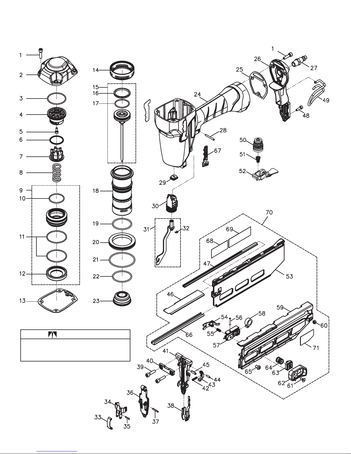
PARTS LEGEND T250S-F16P Part #515500
1 515501 7 Hex. Soc. Hd. Bolt
2 515502 1 Cap
3
*
515503 1 O-Ring
4 515504 1 Top Cap Ring
5 515505 1 Hex. Soc. Hd. Bolt
6 515506 1 Spacer
7 515507 1 Piston Stopper
8 515508 1 Spring
*
9 515509 1 Head Valve Assembly
10 515510 1 O-Ring
*
*
11 515511 O-Ring
*
12 515512 1 Seal
13
*
*
14 515514 1 Collar
15 515515 1 Driver Blade Assembly
*
*
16 515516 1 Wear-Ring
*
17 515517 1 O-Ring
515513 1 Top Cap Seal
2
18 515518 1 Cylinder
19 515519 1 O-Ring
*
20 515520 1 Cylinder-Ring
*
*
21 515521 1 O-Ring
*
22 515522 1 O-Ring
23 515523 1 Bumper
*
24 515524 1 Housing
*
25 515525 1 End Cap Seal
26 515526 1 End Cap
27 615920 1 Air Plug
28 515528 4 Spring Pin
29 515529 1 Bumper Seal
30 515530 1 Depth of Drive A
31 515531 1 WCE Connector
32 403713 1 E-Ring
33 515533 1 Latch Spring Assembly
34 515534 1 Latch
35 515535 1 Spring Pin
36 515536 1 Door
37 515537 1 Spring Pin
38 515538 1 WCE
39 515539 2 Hex. Soc.Hd. Bolt
40 515540 1 Set Plate
41 515541 1 Nose
42 617456 1 Spring
43 515543 1 Lock-out Lever
44 515544 1 Spring Pin
45 515545 1 Spring Pin
46 515546 1 Upper Plate
47 515547 1 Nail Guide
48 515548 2 Hex. Soc.Hd. Bolt
49 515549 1 Belt Hook
50 515550 1 Trigger Valve Assembly
51 617780 1 Spring
52 515552 1 Selectable Trigger
53 515553 1 Magazine (Right)
54 515554 1 Pusher
55 515555 1 Spring
56 515556 1 Spring Pin
57 515557 1 Pusher Seat Assembly
58 515558 1 Roll Spring
59 515559 1 Magazine (Left)
60 515560 2 Lock Nut
61 515561 1 Flat self-tapping Bolt
62 515562 1 Pusher Upper seat
63 515563 1 Push Button
64 515564 1 Spring
65 515565 2 UM. HD. Bolt
66 515566 1 Lower Plate
67 515567 2 Logo Label
68
**
515568 1 Warning Label
69 515569 1 Model Label
70 515570 1 Magazine Assembly
71 515571 1 Lock Label
* Denotes Normal Wear Items.
** Make sure Warning Label (515568) is properly affixed.
Replace if necessary.
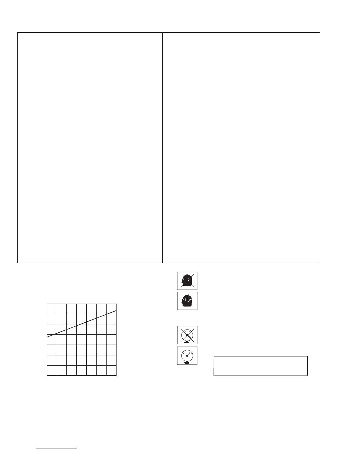
AIR CONSUMPTION CHART
.040
.035
.030
.025
.020
.015
AIR CONSUMPTION-CFM FASTENER
.010
AIR PRESSURE-PSIG
.
.034
11010090807060
120
10
SAFETY INSTRUCTIONS
WEAR EYE AND HEARING PROTECTION
Always wear hearing protection and eye protection devices,
including side shields when operating or working in the vicinity
of a tool.
DO NOT EXCEED MAXIMUM
RECOMMENDED AIR PRESSURE
60
120
0
60
120
0
Operate the tool using only the recommended air pressure. Do
not exceed the maximum air pressure marked on the tool. Be
sure the air pressure gauge is operating properly and check it
at least twice a day.
Never use any bottled air or gases such as
oxygen to operate the tool since they could cause
the tool to explode.
Page 11
T250S-F16P
515500
WARNING
All parts must be periodically inspected and
replaced if worn or broken.
affect the toolʼs operation and present a safety
hazard.
Failure to do this can
11
Page 12

ACCESSORIES
Safety Glasses
raelC
382104 .oN traP
P
© 2018, Illinois Tool Works, Inc.
An Illinois Tool Works Company
155 Harlem Avenue
Glenview, IL 60025
12
Page 13

Pieza# 515500
MODELO
T250-F16P
Clavadora de Acabado
Recto de Calibre 16
¡IMPORTANTE!
NO DESTRUYE ESTE MANUAL
El cliente tiene la responsibilidad de que todo
el personal de operaciones y servicio lea y
entienda este manual.
Manual de Funcionamiento y
Esquema
17
Page 14

INTRODUCCIÓN
La herramienta Paslode
aplicaciones
usada acorde con las
residenciales. Esta herramienta le provera confiabilidad y eficiencia cuando sea
reglas del fabricante.
de seguridad para comprender como usar
®
T250-F16P
es una herramienta de calidad, diseñada para uso en
Lea cuidadosamente este manual y las instrucciones
le herramienta correctamente.
CONTENIDO
ESPECIFICACIONES DE LA HERRAMIENTA Y SUS SUJETADORES............................3
INSTRUCCIONES DE SEGURIDAD................................................................................... 4
INSTALACIÓN Y OPERACIÓN DE LA HERRAMIENTA.....................................................5
VISTA EXPANDIDA CON LISTADO DE PIEZAS...........................................................10-11
ACCESORIOS....................................................................................................................12
TERMINOS DE LA GARANTIA
Paslode garantiza que sus herramientas mecánicas,
sus piezas y accesorios, que hayan sido comprados
nuevos, están libres de defectos de material y fabricación por el período indicado más abajo, a partir de
la fecha de compra del comprador original.
GARANTÍA DE UN AÑO
La garantía
excepción de aquellas cubiertas por la extención
de garantía.
GARANTÍA LIMITADA ADICIONAL DE CINCO AÑOS
La garantía de cinco años cubre todos los armazones
y ensambles de las tapas.
DECLARACIÓN DE LA GARANTÍA
Esta garantía esta limitada a las herramientas vendidas y revisadas en los Estados Unidos. Para obtener
mas información sobre el servicio de garantía en los
Estados Unido, véa la lista de Centros de Servicio
que fue proporcionada con su herramienta.
de un año cubre todas las
piezas, con
Paslode asume únicamente la responsabilidad de re-
poner cualquier pieza o accesorio que se compruebe
como defectuoso dentro del período especificado.
Cualquier pieza o accesorio de repuesto, entregado de
conformidad con esta garantía, gozará de la garantía por
el período restante de la garantía que cubría a la pieza o
al accesorio originales. Esta garantía no cubre las piezas
que necesitan ser repuestas como consecuencia de su
desgaste normal.
Se cancelará esta garantía a cualquier herramienta
haya sido usada incorrectamente, dañada accidental o
intencionalmente,usada con sujetadores
las
especificaciones, el tamaño o la calidad de
o a la que no se le haya dado el mantenimiento o el uso
adecuado, o que haya sido reparada con
sean marca Paslode, o que en opinión de
sido modificadas o reparadas de manera
contraria al funcionamiento de la herra
PASLODE NO OTORGA NINGUNA GARANTÍA EXPLÍCITA O IMPLÍCITA CON RESPECTO A LA COMER-
CIALIZACIÓN O ADAPTACIÓN AL USO PREVISTO, O
DE CUALQUIER OTRA NATURALEZA, CON EXCEP-
CIÓN DE LO DECLARADO ANTERIORMENTE, y la
responsabilidad de Paslode TAL COMO SE INDICA Y
SE ASUME MÁS ARRIBA reemplaza a todas las otras
garantías que resulten o estén relacionadas con el uso
y funcionamiento de la herramienta, excepto según lo
estipulen las leyes pertinentes. PASLODE NO SERÁ
RESPONSABLE EN NINGÚN CASO POR NINGÚN
DAÑO DIRECTO, INDIRECTO O CONSECUENTE
LUYENDO, PERO SIN LIMITARSE, CUALQUIER
INC
DAÑO RESULTADO DE LA PÉRDIDA DE PRODUC-
CIÓN O GANANCIAS ANTICIPADAS, EL DETERIORO
DE MATERIALES, AUMENTOS EN EL COSTO DE OP-
ERACIÓN O CUALQUIER OTRO.
que no reúnan
Paslode,
piezas que no
Paslode hayan
que afecte o sea
mienta.
que
Paslode se reserva el derecho de cambiar las especificacionnes, el equipo o los
diseños en cualaquier momento, sin aviso previo y sin incurrir en obligación alguna.
2
Page 15

ESPECIFICACIONES DE LA HERRAMIENTA Y LOS SUJETADORES
ESPECIFICACIONES DE LA HERRAMIENTA
NO. de MODELO T25O-F16P (Pieza# 515500)
ALTURA 295mm
ANCHO 74mm
LONGITUD 313mm
PESO 1.8kg
PRESIÓN de OPERACIÓN 80 hasta 120 p.s.i. (5,5 hasta 8,3 bar)
ESPECIFICACIONES de los SUJETADORES
LONGITUD DEL CLAVO 25mm-63mm
DIAMETRO DEL TALLO 16 Calibre
ACOPLAMIENTO DE AIRE:
Esta herramienta utiliza un tapón macho de 1/4" N.P.T. El acoplamiento debe ser
capaz de descargar la presión de aire en la herramienta cuando sea desconectada
del suministro de aire.
OPERACION de PRESIÓN de AIRE:
80 hasta120 p.s.i. Seleccione una presión de aire dentro de
esta gama para obtener el mejor rendimiento.
NO EXCEDA LA PRESIÓN DE AIRE RECOMENDADA.
19
3
Page 16

INSTRUCCIONES DE SEGURIDAD
LA SEGURIDAD ESTA PRIMERO
Estas instrucciones proporcionan la información necesatia para
el funcionamiento sin peligrode las herramientas Paslode. NO
trate de usar su herramienta hasta que no haya léido y entendido todas las precauciones de seguridad y las instrucciones de este manual.
PROTEJASE LOS OJOS Y LOS OIDOS
Use siempre el equipo adecuado para protegerse
los ojos y los oídos que sea conforme con ANZI Z87,
meintras usa una herramienta o trabaja cerca de una
herramienta en uso. Como empleador usted es responsable de imponer el usp del la porteccion de ojo. Lleve
sombreros duros en los ambientes que requieren su uso.
USE SU HERRAMIENTA SOLAMENTE PARA EL
PROPOSITO CON QUE FUE DISEÑADA
No arroje la herramienta al suelo; no golpee el armazón ni la use
como un martillo.
NUNCA USE LA HERRAMIENTA PARA JUGUETEAR
Esta herramienta no es un juguete; por lo tanto no la trate como
tal. Nunca juguetee con ella, ni se apunte a usted mismo ni a
otra persona, aun cuando crea que no está cargada.
NUNCA ASUMAQUE LA HERRAMIENTA ESTA VACIA
Verfique que ho haya sujetadores en elcargador. Aun cuando
crea que está vacía o desconectada, nunca se apunte ni apunte
a otra persona con la herramienta, porque podría dispararse un
sujetador que no esté a la vista.
NUNCA SUJETE EL GATILLO EN LA POSICION DE
CIERRE O DE FUNCIONAMIENTO
Nunca se debe manipular indebidamente o dejar inoperante el
gatillo, o sujetarlo en la posición de cierre o defuncionamiento,
porque se podría disparar un sujetador al oprimirse el elemento
de contacto.
NO CARGUE SUJETADORES CUANDO LA LINEA DE
AIRE COMPRIMIDO ESTE CONECTADA, O CUANDO
EL GATILLO O EL ELEMENTO DE CONTACTO ESTE
OPRIMIDO.
Antes de cargar sujetadores en la herramienta, verifique que la
línea de aire comprimido esté desconectada y que ni el gatillo ni
el elemento de contacto estén oprimidos.
DESCONECTE LA HERRAMIENTA CUANDO NO
LA ESTE USANDO
Siempre desconecte la herramienta de la línea de aire
comprimido cuando no la esté usando o al dejar su lugar de
trabajo. Nunca la descuide, porque cualquier persona que no
esté familiarizada con ella podría lastimarse o lastimar otros.
TOME LA HERRAMIENTA SOLAMENTE POR EL
MANGO
Siempre tome la herramienta sólo por el mango. Nunca la
tome por la manguera o con el gatillo oprimido, porque se
podría disparar un sujetador y herirlo o herir a otra persona.
NO ALTERE EL ARMAZON DE LA HERRAMIENTA
El armazón de la herramienta es un recipiente a presión y nunca
se debe grabar en su superficie el nombre de su compañia, el
del área de trabajo, ni ningún otro detalle.
DESCONECTE LA HERRAMIENTA PARA HACER
REPARACIONES O ELIMINAR OBSTRUCCIONES
Nunca trate de eliminar obstrucciones o reparar una herramienta sin haberla desconectado de la línea de aire compromido
y quitado todos los sujetadores.
USE SIEMPRE LOS ADAPTADORES APROPIADOS
PARA SU HERRAMIENTA
Se debe conectar a la herramienta solamente conectores
neumáticos MACHOS, para permitir que el aire de alta presíon salga tan pronto como se desconecte la línea de aire
comprimido.
NUNCA coloque enlaces HEMBRAS
en la herramienta, porque atrapan el aire a alta presíon al
desconectar la línea de aire comprimido, dejándola cargada y
lista para disparar por lo menos un sujetador.
de desconexíon rápida
NO EXCEDA LA PRESION NEUMATICA MAXIMA
RECOMENDADA
La herramienta debe funcionar sólo con la presíon neumática recomendada. No exceda la presíon neumática máxima marcada
en la herramienta. Verifique por lo menos dos veces al día que
el calibre de la presíon neumática funcione correctamente.
Nuna use aire o gases envasado, como el oxígeno, para hacer
funcionar la herramienta porque podrían hacer que explotara.
No haga funcionar en atmósferas explosivas.
USE LA HERRAMIENTA SOLAMENTE SOBRE UN
MATERIAL DE TRABAJO
La herramienta debe funcionar sólo cuando esté en contacto
con el material de trabajo. Debe tener mucho cuidado cuando el
material sea delagado o trabaje cerca de las aristas del mismo,
porque los sujetadores podrían atravesar o salirse del material.
NO DEJE INOPERANTE NI QUITE EL ELEMENTO DE
CONTACTO
Esta herramienta está equipada con un mecanismo de seguridad, llamado elemento de contacto, para prevenir cualquier disp
aro accidental. Nunca manipule indebidamente, deje inoperante,
ni quite el elemento de contacto. No use la herramienta a menos
que dicho elemento funcione correctamente, porque podría
producirse un disparo imprevisto.
La falta de observación de cualquiera de estas instrucciones puede ser causa de graves
lesiones personales, tanto al operador de la herramienta comoa quienes estén cerca de
ella o de daños materiales o a la herramienta
Comuníquese con el representante de Paslode sobre la presentación de Programa de Alerta sobre
Seguridad.
-
PELIGRO
.
4
INSPECCIONE LA HERRAMIENTA PARA LA OPERACION APROPIADA
USE SOLAMENTE PIEZAS Y SUJETADORES RECOMENDADOS POR PASLODE
Use sólo piezas y sujetadores específicamente diseñados y
recomendados por Paslode para usar con esa herramienta
y para la tarea requerida. Si se usan piezas o sujetadores no
autorizados o se modifica de alguna forma la herramienta, se
pueden crear situaciones peligrosas. Vuelva a colocar todas
las etiquetas de precaucíon que flaten. Consulte el diagrama
de la herramienta sobre el número de cada parte y su ubligación correcta.
Page 17

Característica de bloqueo del proceso
FUNCIONAMIENTO DE LA
–
HERRAMIENTA
Sujetadores
El pasador de acabado Paslode T250S-F16P
acciona pasadores Paslode de calibre 16
diseñados para usarse con la herramienta. El uso
de sujetadores que no cumplan los estándares de
Paslode podría causar daños en las herramientas
y anulará todas las reclamaciones de garantía.
Cargando sujetadores
Paso 1:
bado Paslode con el canal de clavitos plateado en
la parte posterior del cargador e intro
dos tiras. Empuje las tiras de clavos hacia adelante.
Alinee las cabezas del los clavos de aca
®
®
duzca una o
Ajuste de profundidad de Drive
Desconectar el suministro de aire.
La profundidad de ajuste de accionamiento se hace
girando la rueda de ajuste situado debajo del gatillo.
-
–
Para desatorar la clavadora
Un problema típico que puede encontrar es una
clavadora con clavos atorados. Debido al diseño
único de la clavadora Paslode, es muy sencillo sacar
los clavos atorados:
Paso 2:
del cargador hasta que el seguidor haya pasado la
última tira de clavos. Suelte la palanca del seguidor
y deje que el mismo mueve los clavos hacia adelan
te dentro de la boca de la herramienta.
Paso 3:
recarga, marcada en el lado del cargador, usted
puede introducir una nueva tira de clavos. Cuando
la flecha de seguidor alcance al área de bloqueo,
la herramienta se bloquea automáticamente para
evitar su funcionamiento. Para desenganchar la her
ramienta, recargue simplemente otra tira de clavos.
Tire del seguidor hacia la parte posterior
Cuando la flecha aparezca en el área de
-
1. Disconecte el aire.
2. Deslice el seguro para soltar la quía delantera
y hágala pivotear hacia adelante.
3. Quite las clavos atorados y empuje la hoja del
impulsador hacia atrás hasta la posición normal
de retorno.
4. Cierre la guía delantera y asegúrela. Verifique
que el elmento de contacto no esté obstruido.
El propósito de esta característica es evitar ciclos
en blanco innecesarios, lo que podría dañar las
maderas y dañar los componentes de la herramienta.
Se colocarán 10 clavos en el cargador cuando el
seguidor alcance el área de bloqueo. Cuando
cambie la longitud o la carga del sujetador al
del día de trabajo, debe inspeccionar el cargador y
principio
la nariz para los sujetadores que queden en el visible
a menos que abra la nariz de la herramienta.
5
Page 18

OPERACIÓN DE LA HERRAMIENTA
Métodos de disparo:
El clavador de acabado Paslode T250S-F16P tiene un
Sistema que se puede cambiar de secuencial a con-
tacto viaje. Para activar el gatillo, pulse el botón redon-
do en el lado izquierdo del gatillo y gire el lado derecho.
Del botón al método de activación deseado. El TTT
Indica disparo de contacto y el T indica secuencia
operación.
Sucesiva (Bounce) de conducción -
Agarre firmemente el mango.
Apriete el gatillo y mueva la herramienta a lo largo de
la pieza con un movimiento de rebote, deprimiendo el
contacto de trabajo elemento en los puntos en los que
desea abrochador.
Apriete el gatillo y mueva la herramienta a lo largo de
la pieza
PELIGRO
No sujete ni sostenga el gatillo con ninguna
otra cosa que no sea la mano.
Quitar las Uñas
Para descargar los clavos, simplemente tire del seguidor
hacia la parte posterior del cargador y presione el botón
de bloqueo central en el seguidor. La moverá el seguidor
hacia afuera y permitirá que los clavos pasen por delante
del seguidor y por la parte posterior del cargador.
Para liberar la cerradura, simplemente tire del seguidor
hacia atrás y el botón de bloqueo se liberará y permitir
que el
seguidor se mueva hacia adelante.
Cuando el número deseado de sujetadores ha sido
dispare el gatillo de la herramienta para evitar descarga del sujetador.
Posición de impulso
Indicador
por salto
de posición
Operación
Secuencial
Operación Secuencial -
El ajuste secuencial T evita sucesivas o "rebote"
conducción.
Presione el elemento de contacto de trabajo y manténgalo contra la superficie de trabajo antes de tirar del
gatillo.
Gancho reversible de la correa:
El gancho de la correa se puede cambiar desde el lado
izquierdo de la herramienta a la derecha. Para cambiar
la posición, apretar la base del gancho de cinturón y
sacarlo de la herramienta y la herramienta de y posicionarlo en el lado deseado.
Después de accionar cada sujetador, libere completamente el dispare y levante la herramienta de la superficie de trabajo.
6
Page 19

MANTENIMIENTO
El mantenimiento de cualquier herramienta Paslode es
simple. Su funcionamiento sin problemas y la prolongación
de la vida de la herramienta se logran siguiendo un sencillo procedimiento. Las personas encargadas de usar y
mantener la herramienta deben leer las instrucciones de
seguridad y mantenemiento. Estudie los diagramas antes
de hacer cualquier reparación.
Las herramientas neumáticas deben revisarse periódicamente, y se deben cambiar las piezas gastadas o dete
rioradas para que la herramienta siga funcionando con
eficiencia y sin peligro. Además, se debe revisar la tabla
de mantenimiento frecuentemente.
Cuando Hace Mucho Frio
Cuando la temperatura es inferior a la de congelamiento,
las herramientas deben mantenerse a la temperatura
ambiente por el método más seguro y conveniente. De lo
contrario, aconsejamos seguir el siguiente procedimiento
para calentar las piezas de la herramienta.
■ Disminuya la presión regulada del aire a 30 psi.
■ Quite todos los sujetadores de la herramienta.
■
Conecte una línea de aire y dispare la herramienta
sin clavos. La presión reducida del aire será suficiente
para lograrlo. El funionamiento a poca velocidad
tiene la tendencia de calentar las partes movibles.
Disminuyendo la velocidad del pistón le da cierta
elasticidad al amortiguador y los anillos-o.
PRECAUCIÓN
®
-
Probar la Herramienta Después de Darle
Servicio
Después de reemplazar una o más piezas, es importante
comprobar si la herramienta funciona como es debido.
Esto asegura que todas las piezas estén puestas correctamente, que la herramienta esté segura y que fun
cione correctamente.
■ Verifique que ninguna pieza esté floja.
■
■ Verifique que el cargador esté colocado
■
■
■
■ Pruebe la herramienta impulsando sujetadores en
■ Verifique que no haya pérdidas de aire en la her-
■
dor esté al ras con el material de trabajo.
Compruebe que el elemento de contacto haya sido
correctamente instalado en relación con el gatillo y
que ambas piezas se muevan libremente.
correctamente.
Verifique que la información sobre seguridad, que
está en la herramienta, sea legible.
Use solamente sujetadores aprobados por Paslode
y compruebe que sean los apropiados para su
aplicación.
Verifique que se haya conectado firmemente un
adaptador macho a la herramienta.
unmaterial de trabajo idéntico al de la aplicación.
ramienta durante las pruebas y revise la secuencia
apropiada de funcionamiento.
Asegure que todos los sujetadores sean impulsados
a la misma profundidad y que la cabeza del sujta-
®
-
Nunca dispare la herramienta sin clavos a
alta presión.
■
Una vez que la herramienta se haya calentado, ajuste
nuevamente el regulador a la presión apropiada para
trabajar y cargue de nuevo la herramienta.
■ Abra, por lo menos diariamente, el drenaje del tan-
que del compresor del aire para eliminar cualquier
humedad, cuando haga mucho frío o el grado de
humedad sea muy alto. Poniendo una pequeña
cantidad de descongelante en el tanque evitará que
la humedad se congele.
Usando la siguiente tabla de mantenimiento es posible
resolver rápidamente y fácilmente la mayoría de los pe
queños problemas. Si un determinado problema persiste,
comuniquese con el representante de Paslode.
®
-
-
-
28
7
Page 20

MANTENIMIENTO (continuación)
Desconecte la herramienta al hacer cualquier
reparación o eliminar cualquier obstrucción.
TABLA DE MANTENIMIENTO
ACTIVIDAD POR QUE COMO
PRECAUCIÓN
Drene el filtro de la línea de aire a
diario.
Limpie el elemento del filtro;
luego, sople aire a través del filtro
en la dirección opuesta a la
corriente normal.
Verifique que todos los tornillos de
la herramienta estén apretados.
Revise si el elemento de contacto
funciona correctamente.
Mantenga limpios los mecanismos
del cargador y del alimentador.
Para evitar que se acumulen la
humedad y la suciedad.
Para evitar que la suciedad obstruya el filtro.
Para evitar pérdidas de aire y
asegurar el buen funcionamiento
de la herramienta.
Para promover la seguridad del
operador y el buen funcionamiento
de la herramienta.
Par prevenir que se obstruyan los
sujetadores.
Abra la llave de escape.
(La mayoría de los sistemas
neumáticos la tienen.)
Lave con agua y jabón, o siga las
instrucciones del fabricante.
Revise los tornillos a diario.
Límpielo con aire a diario.
Límpielos con aire a diario.
Use solamente piezas de repuesto
Paslode.
Para que la herramienta continúe
funcionando eficientemente y
mantener vigente la garantía de
Paslode.
8
Solicite al representante de
Paslode cualquier pieza de
repuesto que necesite.
Page 21

GUÍA PARA SOLUCIONAR
PROBLEMAS
PROBLEMA CORRECCIÓN
PRECAUCIÓN
Desconecte la herramienta al repararla
o desatascarla.
Las sujeciones no entran por completo en la madera.
Las sujeciones entran bien durante la operación
normal, pero no entran por completo cuando
aumento la velocidad.
Las sujeciones penetran demasiado profundo
en la madera.
La sujeción se atasca en la punta de la herramienta.
La herramienta salta durante la operación –
a veces no salen las sujeciones.
Ajuste la profundidad de penetración (retraiga
la longitud).
Aumente la presión del aire (sin exceder los 120 psi).
Aumente el caudal de aire a la herramienta –use
líneas de aire más grandes (con un DI de 3/8"
como mínimo)
Ajuste la profundidad de penetración (extienda
la longitud)
Reduzca la presión del aire.
Abra la traba de la guía frontal, libere la sujeción
atascada y cierre bien la traba.
Verifique que el cargador tenga las sujeciones
correctas. El seguidor del cargador debe deslizarse
libremente. Límpielo si está sucio.
Asegúrese de usar las sujeciones correctas.
Use solo sujeciones que cumplan con las
especificaciones de Paslode
®
.
La herramienta funciona pero no salen
las sujeciones.
Pierde aire por la tapa cuando la herramienta está
conectada al aire.
Aumente el caudal de aire a la herramienta – use
líneas de aire más grandes (con un DI de 3/8"
como mínimo).
Ajuste el elemento de contacto, si puede.
Verifique que el cargador tenga las sujeciones
correctas. Las sujeciones deben deslizarse
libremente sin presión del seguidor.
Abra la traba de la guía frontal y verifique que no
haya sujeciones atascadas ni suciedad en la punta.
Despeje cualquier obstrucción.
Aumente la presión del aire (sin exceder los 120 psi).
Ajuste los tornillos allen.
9
Page 22

LISTA DE PIEZAS,
T250S-F16P Part #515500
1 515501 7 Hex. Soc. Hd. Bolt
2 515502 1 Cap
3
*
515503 1 O-Ring
4 515504 1 Top Cap Ring
5 515505 1 Hex. Soc. Hd. Bolt
6 515506 1 Spacer
7 515507 1 Piston Stopper
8 515508 1 Spring
*
9 515509 1 Head Valve Assembly
10 515510 1 O-Ring
*
*
11 515511 O-Ring
*
12 515512 1 Seal
13
*
*
14 515514 1 Collar
15 515515 1 Driver Blade Assembly
*
*
16 515516 1 Wear-Ring
*
17 515517 1 O-Ring
515513 1 Top Cap Seal
2
18 515518 1 Cylinder
19 515519 1 O-Ring
*
20 515520 1 Cylinder-Ring
*
*
21 515521 1 O-Ring
*
22 515522 1 O-Ring
23 515523 1 Bumper
*
24 515524 1 Housing
*
25 515525 1 End Cap Seal
26 515526 1 End Cap
27 615920 1 Air Plug
28 515528 4 Spring Pin
29 515529 1 Bumper Seal
30 515530 1 Depth of Drive A
31 515531 1 WCE Connector
32 403713 1 E-Ring
33 515533 1 Latch Spring Assembly
34 515534 1 Latch
35 515535 1 Spring Pin
36 515536 1 Door
37 515537 1 Spring Pin
38 515538 1 WCE
39 515539 2 Hex. Soc.Hd. Bolt
40 515540 1 Set Plate
41 515541 1 Nose
42 617456 1 Spring
43 515543 1 Lock-out Lever
44 515544 1 Spring Pin
45 515545 1 Spring Pin
46 515546 1 Upper Plate
47 515547 1 Nail Guide
48 515548 2 Hex. Soc.Hd. Bolt
49 515549 1 Belt Hook
50 515550 1 Trigger Valve Assembly
51 617780 1 Spring
52 515552 1 Selectable Trigger
53 515553 1 Magazine (Right)
54 515554 1 Pusher
55 515555 1 Spring
56 515556 1 Spring Pin
57 515557 1 Pusher Seat Assembly
58 515558 1 Roll Spring
59 515559 1 Magazine (Left)
60 515560 2 Lock Nut
61 515561 1 Flat self-tapping Bolt
62 515562 1 Pusher Upper seat
63 515563 1 Push Button
64 515564 1 Spring
65 515565 2 UM. HD. Bolt
66 515566 1 Lower Plate
67 515567 2 Logo Label
68
**
515568 1 Warning Label
69 515569 1 Model Label
70 515570 1 Magazine Assembly
71 515571 1 Lock Label
*
**
Indica piezas de desgaste normal.
Asegure que la Etiqueta de Advertencia (515568)
este bien pegada. Reemplaze si es necesario.
TABLA DE CONSUMO DE AIRE
.040
.035
.030
.025
.020
.015
.010
CONSUMO DE AIRE -SCFM SUJETADOR
PRESIÓN DE AIRE
.
.034
11010090807060
120
10
INSTRUCCIONES DE SEGURIDAD
USE PROTECCIÓN PARA OJOS Y OÍDOS.
Siempre use protección para oídos y equipo de seguridad para los ojos, incluyendo protectores laterales
cuando este manejando o trabajando en los alred-
edores de una herramienta.
NO SOBRE P
AIRE RECOMEND
Solo opere la herramienta usando la presión de aire
recomendada. No sobre pase la maxima presión de
aire marcada sobre la herramienta. Asegure que el
indicador de presi
reviselo por lo menos dos veces al día.
Nunca use algún aire o gas embotellado tal como el
oxígeno para funcionar la herramienta ya que pueden
causar que la herramienta explote.
ASE LA MAXIMA PRESIÓN DE
ADA
ón
de aire este trabajando bien y
Page 23

T250S-F16P
515500
ADVERTENCIA
Todas las piezas deben ser inspeccionadas
periódicamente y reemplazadas si están gastadas o rotas. Si no lo hace, puede afectar el
funcionamiento de la herramienta y representar un peligro para la seguridad.
11
Page 24

ACCESORIOS
Lentes de Seguridad
Claros
Pieza No. 401382
P
PRINTED IN U.S.A.
© 2018, Illinois Tool Works, Inc.
An Illinois Tool Works Company
155 Harlem Avenue
Glenview, IL 60025
12
Page 25

12
Glenview, IL 60025
155 Harlem Avenue
Une compagnie d'Illinois Tool Works
®
/MD
Pièce n° 401382
Transparentes
Lunettes de sécurité
ACCESSOIRES
Page 26

11
la sécurité.
fonctionnement de l'outil, et cela peut créer un risque pour
à les remplacer au moment opportun peut affecter le
doivent être remplacées si usées ou brisées. Tout manquement
Toutes les pièces doivent être inspectées périodiquement, et
Avertissement
515500
T250S-F16P
Page 27

10
10
MAXIMALE RECOMMANDÉE
NE DÉPASSEZ PAS LA PRESSION D'AIR
CONSIGNES DE SÉCURITÉ
Étiquette de blocage
Jeu du magasin
Étiquette du modèle
Étiquette d’avertissement
Étiquette de logo
Plaque inférieure
Boulon hex.
Ressort
Bouton poussoir
Siège supérieur du poussoir
Boulon plat auto-taraudeur
Contre-écrou
Magasin (gauche)
Ressort en rouleau
Jeu de siège du poussoir
Tige du ressort
Ressort
Poussoir
Magasin (droite)
Gâchette sélectionnable
Ressort
Jeu de vanne de déclenchement
Crochet de ceinture
Boulon à tête hex.
Guide d’attache
Plaque supérieure
Tige du ressort
Tige du ressort
Levier de blocage
Ressort
Nez
Plaque de retenue
Boulon à tête hex.
WCE
Tige du ressort
gaz en bouteille peuvent faire exploser l’outil.
de l’oxygène, pour faire fonctionner cet outil, puisque ces
N’utilisez jamais d’air ou de gaz en bouteille, tel que
fois par jour.
d’air fonctionne correctement, et vérifiez-le au moins deux
indiquée sur l’outil. Assurez-vous que l’indicateur de pression
recommandée. Ne dépassez pas la pression d’air maximale
Utilisez l’outil uniquement avec la pression d’air qui est
.034
.
ou travaillez à proximité d’un outil.
des yeux, y compris des écrans latéraux, lorsque vous utilisez
Portez toujours des équipements de protection de l’ouïe et
PORTEZ UNE PROTECTION POUR LES YEUX ET POUR L’OUÏE
71 515571 1
515570 1
70
515569 1
69
68
67
66
65
64
63
62
61
60
59
58
57
56
55
54
53
52
51
50
49
48
47
46
45
44
43
42
41
40
39
38
**
515568 1
515567 2
515566 1
515565 2
515564 1
515563 1
515562 1
515561 1
515560 2
515559 1
515558 1
515557 1
515556 1
515555 1
515554 1
515553 1
515552 1
617780 1
515550 1
515549 1
515548 2
515547 1
515546 1
515545 1
515544 1
515543 1
617456 1
515541 1
515540 1
515539 2
515538 1
37 515537 1
Porte
Tige du ressort
Loquet
Jeu de ressort de loquet
Anneau en E
Connecteur WCE
Profondeur d’entraînement A
Sceau du pare-chocs
Tige du ressort
Prise d’air
Bouchon du bout
Scellement du bout
Bâti
Pare-chocs
Joint Torique
Joint Torique
Collet de cylindre
Joint Torique
Cylindre
Joint Torique
Bague d’usure
Jeu de tête d’entraînement
Collet
Sceau supérieur
Scellement
Joint Torique
2
Joint Torique
Ensemble de vanne de tête
Ressort
Butée du piston
Espaceur
Boulon à tête hex.
Anneau-bouchon supérieur
Joint Torique
Capuchon
Boulon à tête hex.
CONSOMMATION D’AIR - PIEDS CUBE/MINUTE / ATTACHE
.010
.015
.020
.025
.030
.035
.040
TABLEAU DE CONSOMMATION D’AIR
515513 1
515503 1
2 515502 1
1 515501 7
soit apposée correctement. Remplacez-la au besoin.
** Assurez-vous que l’étiquette d’avertissement (515568)
* Indique les articles qui présenteront une usure normale.
36 515536 1
35 515535 1
34 515534 1
33 515533 1
32 403713 1
31 515531 1
30 515530 1
29 515529 1
28 515528 4
27 615920 1
26 515526 1
25 515525 1
*
24 515524 1
23 515523 1
*
22 515522 1
*
21 515521 1
*
20 515520 1
*
19 515519 1
*
18 515518 1
17 515517 1
*
16 515516 1
*
*
15 515515 1
14 515514 1
*
*
13
12 515512 1
*
11 515511
*
*
10 515510 1
9 515509 1
*
8 515508 1
7 515507 1
6 515506 1
5 515505 1
4 515504 1
3
*
T250S-F16P Pièce no 515500
LÉGENDE DES PIÉCES
Page 28

9
Les attaches ne s’enfoncent pas complètement
vitesses plus élevées.
alimenté en air.
Serrer les vis du capuchon.
Augmenter la pression d’air (ne pas dépasser 120 psi).
de bourrages ou de débris, le cas échéant.
Ouvrir le loquet du guide frontal et vérifier la présence
sans pression du pourvoyeur.
appropriées. Les attaches doivent glisser librement
Vérifier que le magasin contient des attaches
Ajuster l’élément de contact lorsque cela est possible.
d’air plus gros (diamètre intérieur d’au moins 3/8 po).
Augmenter le flux d’air vers l’outil; utiliser des tuyaux
spécifications de Paslode®.
Utiliser uniquement des attaches qui répondent aux
S’assurer que des attaches appropriées sont utilisées.
librement. Si nécessaire, retirer les débris présents.
appropriées. Le pourvoyeur du magasin doit glisser
Vérifier que le magasin contient des attaches
Des fuites d’air au capuchon lorsque l’outil est
attache n’est éjectée.
L’outil semble fonctionner, mais aucune
temps, aucune attache n’est éjectée.
L’outil saute durant l’utilisation; de temps en
coincée, et refermer le loquet de façon sécuritaire.
Ouvrir le loquet du guide frontal, retirer l’attache
Réduire la pression d’air.
(augmenter la longueur).
Ajuster le réglage de profondeur d’entraînement
moins 3/8 po).
tuyaux d’air plus gros (diamètre intérieur d’au
Augmenter le flux d’air vers l’outil; utiliser des
Augm
enter la pression d’air (ne pas dépasser 120 psi).
la longueur).
Ajuster le réglage de profondeur d’entraînement (diminuer
Les attaches se coincent dans le nez de l’outil.
dans le bois.
Les attaches s’enfoncent trop profondément
s’enfoncent pas complètement à des
d’une utilisation normale, mais elles ne
Les attaches pénètrent correctement lors
dans le bois.
PROBLÈME MESURE CORRECTIVE
ATTENTION
du dégagement de bourrages.
Débrancher l’outil lors d es réparati ons ou
DÉPANNAGE PAR L’UTILISATEUR
Page 29

Purgez le filtre de la conduite
Pour prévenir l’accumulation
Ouvrez le robinet de purge
8
local.
MD
Paslode
auprès de votre détaillant
rechange dont vous avez besoin
Commandez toute pièce de
soufflant.
Nettoyez quotidiennement en
soufflant.
Ne
ttoyez quotidiennement en
quotidiennement.
Vérifiez le bon serrage des vis,
les instructions du fabricant.
Lavez à l’eau savonneuse ou selon
ce type de robinet).
d’alimentation en air comportent
manuelle (la plupart des systèmes
.
MD
l’outil Paslode
de l’outil, et maintenir la garantie de
Pour préserver le bon fonctionnement
Pour prévenir le blocage des attaches.
efficace de l’outil.
l’utilisateur, et un fonctionnement
Pour favoriser la sécurité de
plus efficace.
favoriser un fonctionnement
Pour prévenir les fuites d’air, et pour
par la saleté
Pour prévenir l’obstruction du filtre
d’humidité et de saleté.
.
MD
rechange Paslode
Utilisez uniquement des pièces de
d’alimentation propres.
Gardez le magasin et le dispositif
correctement.
pointe de contact fonctionne
Assurez-vous que l’élément de
soient bien serrées.
Vérifiez que toutes les vis de l’outil
en direction opposée du débit normal.
soufflez de l’air à travers le filtre,
Nettoyez l’élément du filtre, puis
d’air (quotidiennement).
MESURE À PRENDRE POURQUOI COMMENT
TABLEAU D’ENTRETIEN
une réparation ou un déblocage
Débranchez l’outil avant d’effectuer
MISE EN GARDE
ENTRETIEN - suite
Page 30

dans
MD
7
détaillant Paslode pour de l’assistance.
ci-dessous. Si le problème persiste, communiquez avec votre
ment et facilement, en vous référant au tableau d’entretien
La plupart des problèmes mineurs peuvent être réglés rapide-
MISE EN GARDE
affleurement avec la pièce à travailler.
même profondeur, et que la couronne des attaches soit à
❑
Assurez-vous que toutes les attaches soient enfoncées à la
correcte.
testez aussi que la séquence de son fonctionnement soit
❑
Vérifiez la présence de fuite d’air sur l’outil pendant le test,
sera utilisé.
travailler qui soit identique à l’application pour laquelle l’outil
❑
Testez l’outil en enfonçant des attaches dans une pièce à
ment sur l’outil, et de manière sécuritaire.
❑
Assurez-vous qu’un raccord d’air mâle soit connecté solidel’application.
l’outil, et vérifiez qu’elles soient bien appropriées pour
❑
N’utilisez que des attaches approuvées par Paslode
soient bien lisibles.
❑
Assurez-vous que les consignes de sécurité requises sur l’outil
❑
Assurez-vous que le magasin soit fixé correctement.
pièces puissent bouger librement.
correctement relativement à la gâchette, et que les deux
❑
Assurez-vous que l’élément de pointe de contact soit installé
❑
Assurez-vous que toutes les pièces soient bien serrées.
manière appropriée.
réassemblé correctement, est sûr et exécutera les tâches de
vérifier que l’outil fonctionne bien. Ceci assure que l’outil a été
Après avoir remplacé une ou plusieurs pièces, il est important de
Tester L’outil Après une Réparation
sont conçus pour faciliter leur entretien.
MD
ou de givre.
le réservoir peut aussi contribuer à garder l’air libre de gel
au moins une fois par jour. Une petite quantité d’antigel dans
réservoir du compresseur d’air pour purger toute humidité,
❑
Par temps très froid ou humide, ouvrez le purgeur du
rechargez l’outil.
régulateur à la bonne pression de fonctionnement, et
❑
Une fois que l’outil sera réchauffé, réglez à nouveau le
à la haute pression.
Ne jamais tirer à blanc avec l'outil, en recourant
niveau voulu de rebond.
le piston aidera la butée et les joints toriques à atteindre leur
lente aura tendance à réchauffer les pièces mobiles. Ralentir
déclenchement librement. Un fonctionnement à vitesse
La pression d’air réduite sera suffisante pour activer un
❑
Raccordez une conduite d’air et tirez à blanc avec l’outil.
❑
Retirez toutes les attaches de l’outil.
❑ Réduisez la pression d’air régulé à 2,06 bars (30 psi).
sécuritaire. Si cela n’est pas possible, il faut suivre les procédures
être gardés au chaud par tout moyen qui soit pratique et
Si les températures tombent en dessous de zéro, les outils doivent
Entretien par temps froid
Les outils pneumatiques doivent être inspectés régulièrement, et
schémas avant d’entamer toute réparation sur cet outil.
comprendre les consignes de sécurité et d’entretien. Examinez les
utile. Toute personne qui utilise ou répare l’outil doit lire et
fonctionnement sans souci, et d’en tirer une longue durée de vie
Quelques détails simples vous permettront d’en assurer le
Les outils Paslode
ENTRETIEN
Page 31

6
moyen que votre main.
MISE EN GARDE
Ne pas coincer ni retenir la gâchette par un autre
la gâchette, et soulevez l'outil de la surface de travail.
Après avoir enfoncé chaque attache, relâchez complètement
sur la gâchette.
maintenez-la contre la surface de travail, avant de presser
Appuyez sur l’élément de pointe de contact de travail et
le déclenchement successif ou « à rebond. »
Le réglage de déclenchement séquentiel (sigle T) empêche
Opération Séquentielle -
séquentielle
Opération
de l'outil, puis, positionnez-le sur le côté voulu.
compressez la base du crochet de ceinture et enlevez-le
au côté droit de l’outil. Pour changer la position,
Le crochet de ceinture peut être changé du côté gauche
Crochet Réversible de Ceinture :
successif (au rebond)
du déclenchement
Indicateur de sélection
Déclenchement
des attaches.
gâchette de l'outil pour éviter tout déclenchement involontaire
Lorsque le nombre souhaité d'attaches a été atteint, relâchez la
possible l'outil au-dessus du point à clouer.
travailler, tout en positionnant aussi soigneusement que
rebonds de l’élément de pointe de contact contre la pièce à
Maintenez la gâchette enfoncée, et continuez à faire des
enfoncer une attache.
ant l’élément de pointe de contact aux points où vous voulez
travailler, dans un mouvement ponctué de rebonds, en appuyPressez la gâchette et déplacez l'outil le long de la pièce à
Saisissez fermement la poignée.
Déclenchement Successif (au Rebond) -
libéré, et permettra au pourvoyeur de bouger vers l’avant.
l'arrière du magasin, le bouton de verrouillage sera alors
relâcher le verrou, tirez simplement le pourvoyeur vers
plus loin que le pourvoyeur, et à l'arrière du magasin. Pour
dégager le pourvoyeur, et permettra aux attaches de glisser
central de verrouillage sur le pourvoyeur. Le verrou va
pourvoyeur à l'arrière du magasin, et appuyez sur le bouton
Pour décharger les attaches, tirez simplement sur le
Décharger les Attaches :
que le sigle T indique un déclenchement séquentiel.
Le sigle T T T indique un déclenchement au contact, alors
déclenchement voulue.
le côté droit du bouton pour choisir la méthode de
bouton rond sur le côté gauche de la gâchette, et tournez
contact. Pour commuter le déclenchement, appuyez sur le
déclenchement séquentiel à un déclenchement au
système de déclenchement qui peut être commuté d’un
Méthodes de déclenchement :
FONCTIONNEMENT DE L'OUTIL
Page 32

nez de l'outil.
Ces attaches ne seront visibles que si vous ouvrez le
présence d’attaches laissées dans l’outil.
devez inspecter le magasin et le nez pour détecter la
chargement au début de la journée de travail, vous
changement de la longueur des attaches, ou du
pourvoyeur atteint la zone de verrouillage. Lors du
attaches sont laissées dans le magasin lorsque le
endommager les composantes de l'outil. Dix (10)
vide, ce qui pourrait gâcher les planches en bois, et
Le but de cette fonction est d'empêcher un cycle à
5
t à sa
ez le
Fonction de Verrouillage
de pointe de contact puisse bouger librement.
rmale.
rontal vers l'avant.
position no
Dégagez le blocage, puis pousser la lame d’entraînemen
3.
guide f
2. Tirez le loquet, pour dégager le guide frontal, puis pivot
Débranchez l'alimentation en air.
1.
facilite grandement le déblocage d’une attache bloquée :
recharger simplement une autre bande d’attaches.
fonctionnement de l'outil. Pour débloquer l'outil,
verrouille automatiquement, pour prévenir tout
pourvoyeur atteint la zone de verrouillage, l'outil se
marquée sur le côté du magasin, vous pouvez insérer
Lorsque le pourvoyeur atteint la zone de recharge,
l'avant, dans le nez de l'outil.
laissez le pourvoyeur pousser les attaches vers
dernière bande d’attaches. Relâchez le pourvoyeur et
magasin, jusqu'à ce que le pourvoyeur dépasse la
ÉTAPE 2 : Ensuite, tirez le pourvoyeur vers l'arrière du
–
Vous pourriez à l’occasion rencontrer le problème d’une attache
Dégager un Bourrage
gâchette.
tournant la roue de réglage, située au-dessous de la
Le réglage de la profondeur d'entraînement se fait en
Débrancher l'alimentation en air.
T250S-F16P permet
MD
d'entraînement
Réglage de la Profondeur
d’attaches. Poussez les bandes d’attaches vers l’avant.
l'arrière du magasin, et insérez une ou deux bandes
Paslode de calibre 16 avec le guide des attaches, à
Chargement des Attaches
réclamation sous garantie.
l’outil, et cela entraînera l’annulation de toute
les normes de Paslode peut causer des dommages à
outil. L'utilisation des attaches qui ne rencontrent pas
lesquelles sont conçues pour être utilisées avec cet
d’enfoncer des attaches Paslode de calibre 16,
Attaches
FONCTIONNEMENT DE L'OUTIL
Page 33

É
É
Ne pas
Assurez-vous que la
PRESSION D'AIR
PASSER LA
4
MISE EN GARDE
de l'outil pour l'emplacement et le numéro de pièce.
POUR SON BON FONCTIONNEMENT
faire fonctionner dans des atmosphères explosives.
l'outil, ceci pourrait faire exploser l'outil.
bouteille tel que de l'oxygène pour faire fonctionner
Ne jamais utiliser de l'air comprimé ou autre gaz en
pression fonctionne adéquatement et en
indiquée sur l'outil.
bon fonctionnement au moins deux fois par jour.r.
jauge de
maximale
recommandées. Ne pas dépasser la pression d'air
N'opérer l'outil que dans les limites de pressions
MAXIMALE RECOMMANDÉE
NE JAMAIS DÉ
au schéma
Remplacez toutes les étiquettes de mise en garde – reportez vous
toute modification de l'outil créent des situations dangereuses.
accomplir. L'utilisation de pièces et attaches non autorisées ou
et recommandées par Paslode pour l'outil et pour le travail à
N'utiliser que les pièces et les attaches spécifiquement conçues
RECOMMANDÉES
N'UTILISER QUE LES PIÈCES ET ATTACHES PASLODE
opérer un outil sale ou qui ne fonctionne pas bien.
Nettoyer l'outil tous les jours et le lubrifier au besoin. Ne jamais
INSPECTER L'OUTIL
vérifier le
laissant ainsi l'outil chargé et capable d'enfoncer une attache.
pression d'air dans l'outil lorsque la source d'air est désaccouplée,
rapide sur l'outil. Les raccords femelles retiennent la haute
Ne JAMAIS installer des raccords FEMELLES à désaccouplement
dans l'atmosphère dès que la ligne à air est désaccouplée.
l'outil, afin que la haute pression d'air dans l'outil puisse se dissiper
N'utiliser que les raccords MÂLES de type pneumatique pour
T
OUJOURS UTILISER LE BON RACCORD POUR L'OUTIL
r
.
blessures sérieuses à l'utilisateur et tierces personnes et pourrait endommager l'outil et autres biens.
Le manque à suivre n'importe laquelle des instructions ci-haut mentionnées pourrait résulter en des
R
VICE L'ÉLÉMENT
T
ACT TOUCHE LA PIÈCE
ACHES LORSQUE LA SOURCE
Communiquez avec votre représentant Paslode pour une présentation du Programme de Sensibilisation sur la Sécurité de Paslode.
accidentellement.
contact ne fonctionne proprement. L'outil pourrait se décharger
contact. Ne pas utiliser l'outil à moins que l'élément de pointe de
modifier
, enlever ou mettre hors service l'élément de pointe de
de contact, afin de prévenir la décharge accidentelle. Ne jamais
L'outil est équipé d'un mécanisme de sécurité, l'élément de pointe
DE POINTE DE CONTACT
NE PAS ENLEVER OU METTRE HORS SE
travail.
minces, ou près des bords et dans les coins, puisque
doublez de précaution avec les pièces de travail
avec la pièce de travail. Même dans cette situation,
L'outil ne devrait être opéré que lorsqu'il est en contact
PIÈCE DE TRAVAIL
FONCTIONNER L'OUTIL SEULEMENT SUR UNE
ATT
r
, mettre hors service ou pincer la gâchette de
les attaches pourraient traverser ou faire ricochet de la pièce de
rechargez l'outil.
et la pointe de contact ne sont pas pressées lorsque vous
Assurez-vous d'avoir désaccouplé l'entrée d'air et que la gâchette
DE TRAVAIL.
L'ÉLÉMENT DE POINTE DE CON
D'AIR EST ACCOUPLÉE, LA GÂCHETTE EST PRESSÉE OU
NE P
AS CHARGER LES
l'élément de pointe de contact touche la pièce de travail.
trait à l'outil d'enfoncer une attache, n'importe quand, lorsque
l'outil en position barrée ou opérationnelle, puisque ceci permetNe jamais modifie
OU OPÉRATIONNELLE.
NE JAMAIS PINCER LA GÂCHETTE EN POSITION BARRÉE
pourrait décharger des attaches non remarquées.
jamais le pointer vers vous ou vers une autre personne. L'outil
Même si vous croyez que l'outil est vide ou est désaccouplé, ne
Vérifiez le magasin pour des attaches qui pourraient y reste
NE JAMAIS PRÉSUMER QUE L'OUTIL EST VIDE
de l'outil.
désaccoupler l'outil de la source d'air et d'enlever toutes attaches
Ne jamais tenter de débloquer ou de réparer l'outil avant de
DÉBLOCAGES
L
LORS DE L'ENTRETIEN OU DES
pourriez décharger l'outil accidentellement et vous
d'air ou avec la gâchette pressée puisque vous
poignée. Ne jamais transporter l'outil par le tuyau
T
oujours transporter l'outil uniquement pas sa
POIGNÉE
NE TRANSPORTER L'OUTIL QUE PAR SA
DÉSACCOUPLER L'OUTI
entreprise, lieu de travail ou toute autre information sur sa surface.
être af
faibli en faisant graver ou poinçonner le nom de votre
Le boitier de l'outil est un conduit de pression et ne devrait jamais
NE PAS AFFAIBLIR LE BOITIER DE L'OUTIL
blesser ou blesser une autre personne.
sures.
son fonctionnement pourraient le manipuler et causer des blessurveillance, puisque de tierces personnes, non familières avec
l'outil vers un autre endroit. L'outil ne doit jamais être laissé sans
lorsque vous quittez le chantier de travail ou que vous transportez
T
oujours désaccoupler l'outil de la source d'air lorsqu'il est remisé,
DÉSACCOUPLER L'OUTIL QUAND IL N'EST PAS UTILISÉ
pas chargé.
ou toute autre personne, même si vous croyez que l'outil n'est
jamais initier des jeux brutaux avec l'outil ou le pointer vers vous
Cet outil n'est pas un jouet donc ne pas l'utiliser comme tel. Ne
NE JAMAIS INITIER DES JEUX BRUTAUX AVEC L'OUTIL
en place.
ce soit ou utiliser l'outil comme marteau pour enfoncer la pièce
Ne pas jeter l'outil à terre, frapper le boîtier de quelque façon que
PRÉVU.
L'OUTIL NE DOIT ÊTRE UTILISÉ QUE POUR SON USAGE
vous assurer du port de l'équipement de protection.
, il en est de votre responsabilité de
ANSI
VOIR LU ET
tant qu'employeur
Z87.1 lors de l'opération de l'outil ou à proximité. En
les yeux et l'ouïe qui se conforment aux normes
Toujours porter de l'équipement de protection pour
POUR LES YEUX ET L'OUÏE.
PORTER DE L'ÉQUIPEMENT DE PROTECTION
OUTES LES PRÉCAUTIONS À PRENDRE ET LES
Porter des casques de sécurité lorsque nécessaire.
INSTRUCTIONS DU MANUEL.
COMPRIS T
NE PAS ESSAYER D'OPÉRER L'OUTIL AVANT D'A
nécessaire pour manipuler les outils Paslode en toute sécurité.
Ces instructions se rapportant à la sécurité donnent l'information
LA SÉCURITÉ AVANT TOUT
CURIT
INSTRUCTIONS SUR LA S
Page 34

3
NE DÉPASSEZ PAS CETTE PRESSION DE FONCTIONNEMENT RECOMMANDÉE
comprise dans cette plage pour obtenir le meilleur rendement de l’outil.
5,5 à 8,3 bars (80 à 120 p.s.i.). Choisissez une pression d’air de fonctionnement
PRESSION D’AIR DE FONCTIONNEMENT :
débranché de l’alimentation en air.
7 mm (0,28 po) ou plus. Le raccord doit pouvoir libérer la pression d’air de l’outil lorsqu’il est
Cet outil utilise un raccord mâle de 1/4 po N.P.T. Le diamètre intérieur doit être de
RACCORDS À AIR DE L’OUTIL
5,5 à 8,3 bars (80 à 120 p.s.i.)
kg
Calibre 16
25 mm à 63 mm (1 po à 2½ po)
1,8
313 mm
74 mm
295 mm
DIAMÈTRE DE L A TIGE
DES CLOUS
LONGUEUR
CARACTÉRISTIQUES DES ATTACHES
PRESSION DE FONCTIONNEMENT
POIDS
LONGUEUR
LARGEUR
HAUTEUR
MODÈLE N° T250S-F16P (Pièce n° 515500)
CARACTÉRISTIQUES DE L’OUTIL
CARACTÉRISTIQUES DE L’OUTIL ET ATTACHES
Page 35

2
D'OPÉRATIONS OU AUTRES.
PRODUCTION, PERTE DE MATERIAUX, COÛTS MAJORÉS
DÉCOULER PAR LA PERTE DE PROFITS ANTICIPÉS, DE
INCLUANT MAIS NON LIMITÉ AUX DOMMAGES POUVANT
DE DOMMAGES DIRECTS, INDIRECTS OU CONSÉQUENTS À,
POURRAIT ÊTRE TENUE RESPONSABLE, EN AUCUN CAS,
l'exception des modalités légales applicables. PASLODE NE
être connexes à l'utilisation et la performance de l'outil, à
qui a trait à toutes autres garanties pouvant provenir de ou
, prime en ce
et la responsabilité de Paslode,
TELLE QUE CITÉE ET CONVENUE CI-DESSUS
CLARATION CI-DESSUS,
CONVENANCE, OU AUTRE, À L'EXCEPTION DE LA DÉIMPLICITE, EN CE QUI À TRAIT À LA COMMERCIALITÉ
PASLODE NE DONNE AUCUNE GARANTIE, EXPRESSE OU
l'outil.
manière telle qu'elle affecte ou amoindrit la performance de
d'après l'expertise de Paslode, a été modifié ou réparé de
endommagé durant le transport ou la manutention, ou bien,
des composantes autres que les pièces originales Paslode,
leur grandeur ou qualité, ayant été mal entretenu, réparé avec
des attaches qui ne rencontrent pas les normes de Paslode,
accidentels ou intentionnels, ou bien utilisé de concert avec
sujetti à de l'abus, une mauvaise utilisation, des dommages
Cette garantie est nulle dans le cas d'un outil qui a été as-
couvercle.
moulées du boîtier et ensemble de
s'applique sur toutes les pièces
Une garantie limitée de cinq ans
DE CINQ ANS
GARANTIE LIMITÉE PROLONGÉE
garantie prolongée.
de remplacement requises par une usure normale.
qui est remplacée. Cette garantie ne s'applique pas aux pièces
la période de garantie résiduelle couvrant la pièce originale
en rapport à cette garantie sera couvert par une garantie pour
spécifiée. Toute pièce de remplacement ou accessoire fourni
pièce ou accessoire prouvé défectueux durant la période
La seule responsabilité de Paslode sera de remplacer toute
liste des centres de service fournie avec votre outil.
aux États-unis et au Canada, veuillez vous referez à la
d'obtenir de l'information visant le service sous garantie
unis et au Canada qui nécessitent des réparations. Afin
Cette garantie est limitée aux outils vendus aux États-
DÉCLARATION DE GARANTIE
des pièces couvertes par une
sur toutes les pièces, à l’exception
Une garantie de un an s’applique
GARANTIE COMPLÈTE D'UN AN
à l’utilisateur original.
ci-dessous suite à la date de livraison
d'œuvre pour la période spécifiée
défectuosités en matériel et main-
et accessoires seront libres de toutes
outils d'ancrage assisté, leurs pièces
Paslode garantit que les nouveaux
GARANTIE DE L’OUTIL ET LIMITES
.................................................................................................12
ACCESSOIRES ................
VUE ÉCLATÉE ET LISTE DES PIÈCES DE RECHANGE ............................................10-11
INSTALLATION ET UTILISATION L’OUTIL ........................................................................5
CONSIGNES DE SÉCURITÉ ...............................................................................................4
CHARACTÉRISTIQUES DE L'OUTIL ET DES ATTACHES ................................................3
pour les travaux de finition résidentielle.
T250S-F16P est un outil de qualité conçu pour être
MD
utilisé
La cloueuse de finition Paslode
INTRODUCTION
Page 36

1
IMPRIM É À TAIWAN
réparation lisent et comprennent ce guide.
utilisateurs et le personnel d’entretien et de
Il incombe au client de s’assurer que tous les
NE PAS DÉTRUIRE
08/18
© Illinois Tool Works Inc., 2018
Calibre 16
Pour Clous Droits de
Cloueuse de Finition
Numéro de pièce 515500
Modèle T250S-F16P
®
/MD
 Loading...