

Paser Unicanplus CF0007UNUN11 Installation Manual
Pag 4
THIS PRODUCT IS COVERED BY TWO-YEAR GUARANTEE FOR ANY
MANUFACTURING TROUBLES. THE WARRANTY IS VALID IF
ACCOMPAINED BY THE INVOICE OF PURCHASE
WARRANTY
The information in this guide are purely for information pu rposes, therefore, are subject to change without notice.
At the time of publication the information is correct and relia ble.
However Pase r can not be held respo nsible for any cons equences resultin g from errors or omissions in this m anual. Paser reserves the right to improve / change the p roduct or manual without obligation to notify users.
INSTALLATION MANUAL
UNICANPLUS
UNIVERSAL CANBUS Adapter
for steering wheel commands
and Autoradios
with wired Remote input rev. 21
DESCRIPTION
UNICANPLUS is a UNIVERSAL adapter for steering wheel commands with CANBUS protocol, the
principal characteristics being its compatibility which extends to a large number of vehicles, listed in
table 1, and to the CLARION - KENWOOD - JVC - ALPINE - PIONEER - SONY autoradios which
have a wired input on the back of the autoradio for control of the remote.
The module not only handles the steering wheel commands but supplies services such as ignition,
slidelights, reverse gear and odometric signals where present on the CANBUS.
The selection of the protocol comes through SELF-RECOGNITION, which means that when the
connections for the insertion of the module to the connector have been completed, the unit will undergo, within about a second, the synchronization and the selection of the right CANBUS protocol of
the auto on which the module is being installed.
Pag 1
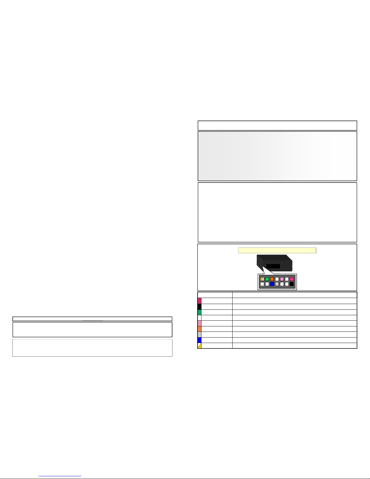
CABLE FUNCTION
RED POSITIVE POWER SUPPLY
BLACK NEGATIVE POWER SUPPLY
GREEN HIGH CAN
WHITE LOW CAN / K-BUS
PINK POSITIVE IGNITION OUTPUT
ORANGE POSITIVE SIDELIGHTS OUTPUT
GREY ODOMETRIC SIGNAL
BLUE POSITIVE REVERSE GEAR OUTPUT
YELLOW/WHITE NEGATIVE HANDBRAKE OUPUT
CABLING DESCRIPTION

SELF-RECOGNITION AND FUNCTIONS
The selection of the protocol comes through SELF-RECOGNITION. After connections for inserting
the module to the connector are terminated, the unit will undertake the synchronization in a few
seconds, signalled by RED quick flashes of the module’s LED.
LED
As soon as the synchronization has been completed, the protocol of the vehicle must be selected.
This operation will be confirmed by the GREEN FLASHING light of the module’s LED.
The unit is ready for SELECTING THE AUTORADIO.
The default module presents the first radio to be selected which is the CLARION, the GREEN LED
carries out 1 FLASH. The table below indicates the position of the radio.
In order to select a different radio press VOLUME + to go onwards or VOLUME - to go backwards..
Once the radio is chosen, confirm with SEEK +. The GREEN LED will become fixed confirming the
selection.
It is also necessary to put the JUMPER JP1 in the correct position for the ALPINE, PIONEER and
SONY autoradios.
Pag 2
LED
1 2 3
J1
J2
J3
J4
J5
JUMPERS
1 - 2 2 - 3
J1
ALPINE - SONY OUTPUT PIONEER OUTPUT
J2
GND BRAKE OUTPUT POSITIVE BRAKE OUTPUT
J3
GND REVERSE OUTPUT POSITIVE REVERSE OUTPUT
J4
BLAUPUNKT DO NOT USE
J5
K-BUS HANDLING CAN-BUS HANDLING
*The jumper J4 must be set if you use a PHONOCAR VM024 and BLAUPUNKT STANDARD radio,
if you use BLAUPUNKT2 (Atlanta110-Madrid210-Toronto410BT-San Francisco310), BLAUPUNKT
NEW YORK 800 or if you use IR jumper J4 doesn't be set.
*The jumper J1 doesn’t be set if you use SUZUKA, DAYTONA 7000 AUTOSONIK and PHONOCAR VM024 radio.
*BUENOS AIRES 200 model it is not equipped of the remote wired input so can be controlled only
with IRR. The profile to set it’s the same used for Kenwood.
LED
CBL007UNAL22 ALPINE
CBL007UNBL12 BLAUPUNKT / BLAUPUNKT 2
CBL007UNJV12
CLARION / JVC / DAYTONA 8000 / INDIANAPOLIS 2 600 /
INDIANAPOLIS 6100 Navi
CBL007UNKE11 KENWOOD
CBL007UNPI12 PIONEER / SONY / DAYTONA 7000
CBL007UNPN21 PANASONIC
ADATTATORE RADIO
Pag 3
TROUBLESHOOTING
• The unit doesn’t work and the LED is off.
• Check the connections of the power supply.
• The unit which is correctly powered,doesn’t work and the LED is off.
• Check the CANBUS connections.
• The unit is connected correctly and the RED LED flashes quickly.
• The unit hasn’t been synchronized with the CANBUS, contact Paser.
• The unit is connected correctly and the RED LED flashes in an irregular way.
• Check the CANBUS connections.
• The unit is connected correctly and the RED LED is on.
• The unit has undertaken the synchronization with the CANBUS but hasn’t been able to
individuate the vehicle, contact Paser.
• The unit is connected correctly but can’t handle the K-BUS protocol.
• Check that the J5 jumper has been inserted between pins 1 and 2.
• The unit is connected correctly, the GREEN LED is on but doesn’t control the
radio.
• Check that the module’s PLUG is connected to the radio’s REMOTE input or contact
Paser.
POWER SUPPLY 10/16 VDC
ABSORPTION AT REST 0,001 A
ABSORPTION WHEN WORKING 0,040 A
MAX CHARGE IGNITION OUTPUT 2,000 A
MAX CHARGE SIDELIGHTS / HANDBRAKE / REVERSE
GEAR OUTPUT / ODOMETRIC SIGNAL
0,040 A
TECHNICAL CHARACTERISTICS
WARNING!
IF YOU NEED TO INSTAL THE SAME IN
A NEW CAR (EVEN IF IN A SAME GROUP MODEL) IT IS NECESSARY
TO RESET THE MODULE.
RESET:
1. WITH THE UNIT POWERED, PRESS AND KEEP PRESSED THE UNICAN BUTTON TILL
THE LED SWITCH OFF.
2. WITH THE LED SWITCHED OFF RELEASE THE BUTTON, THE RESET IS DONE.
 Loading...