

Page 1
PASCO Structures System
®
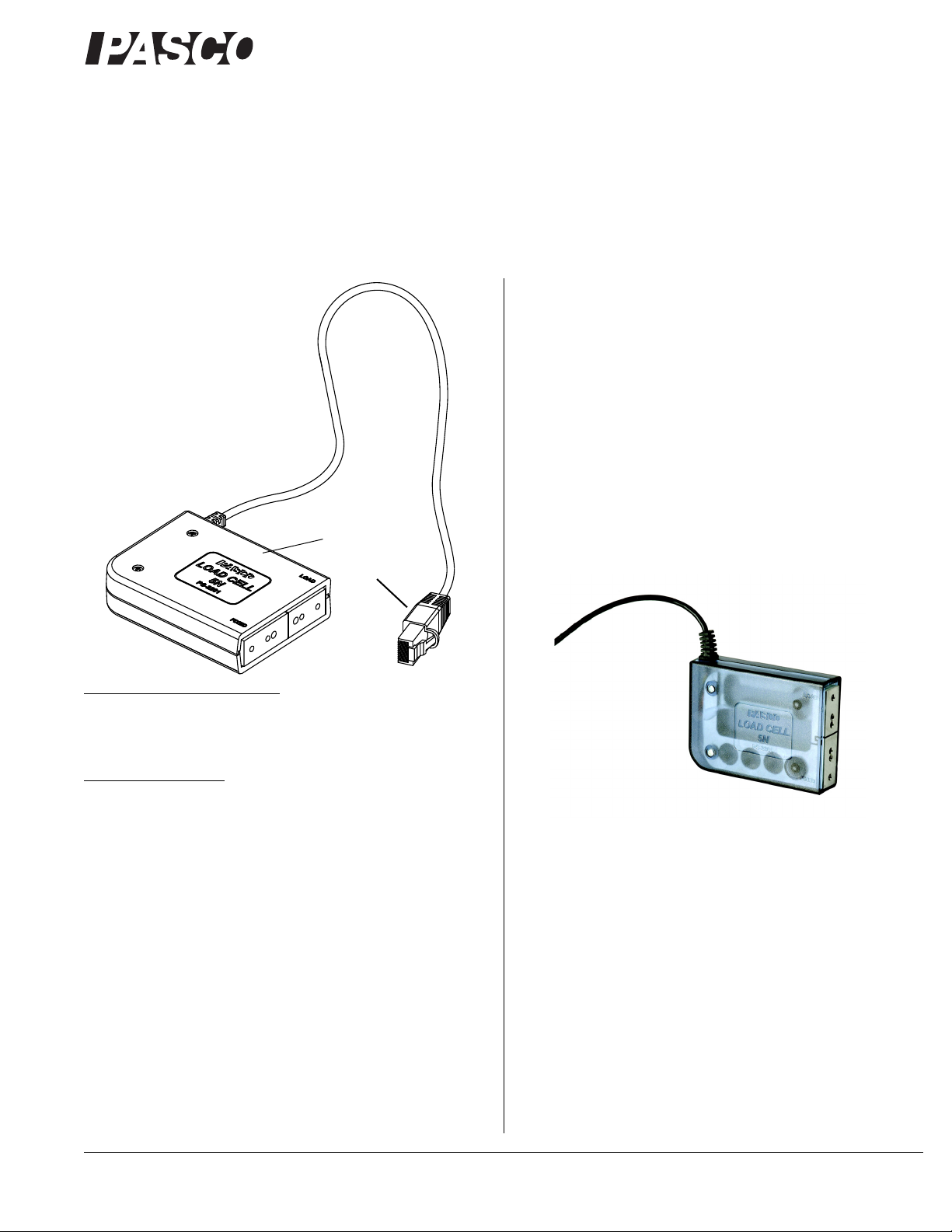
5 N Load Cell
RJ-50 Plug
To find the mass of
the Load Cell beam,
zero the Load Cell
while it is in the
vertical direction, and
then invert it.
Load Cell, 5 N (NI)
PS-2201-NI
When connected to a National Instruments NI-9237 Analog Input
Module, the Load Cell can measure compression and tension
forces in any component of the PASCO Structures System. The
5 N Load Cell can also be used to find acceleration if you measure the force and divide by the mass of the beam.
About the Load Cell
The PS-2201 Load Cell measures forces ranging from -5 N to
+5 N and is wired with a RJ-50 connector for plugging into the
National Instruments NI-9237 Analog Input Module.
Instruction Sheet
012-11989A
*012-11989*
Recommended Equipment
• National Instruments NI-9237 Analog Input Module*
*See www.ni.com for more information
Related Equipment
• NI Structures System (ME-7006)
• NI Driven Structures System (ME-7007)
• Physics Structures Set (ME-6989)
• Truss Set (ME-6990)
• Bridge Set (ME-6991)
• Advanced Structures Set (ME-6992A)
See www.pasco.com for details about PASCO Structures System parts
and sets.
To find the mass of the beam, zero the load cell while it is in the
vertical direction, and then invert it. Convert the measured
weight of the beam to its mass by dividing by 9.8 N/kg.
Figure 1: The 5N Load Cell has a semi-transparent case
The National Instruments NI-9237 Analog Input Module has four
RJ-50 receptacles and an external excitation voltage source. Each
channel on the NI-9237 has an independent 24-bit analog-to-digital converter (ADC) and an input amplifier that enables you to
sample signals from all four channels simultaneously (see Figure
2).
Introduction
The Load Cell, 5 N (NI) for National Instruments (NI) is
designed to work with the PASCO Structures System. For example, the PASCO Structures System includes the ME-6990 Truss
Set, ME-6991 Bridge Set, and the ME-6992A Advanced Structures Set.
800-772-8700 www.pasco.com
Page 2
®
Load Cell, 5 N (NI) PS-2201-NI
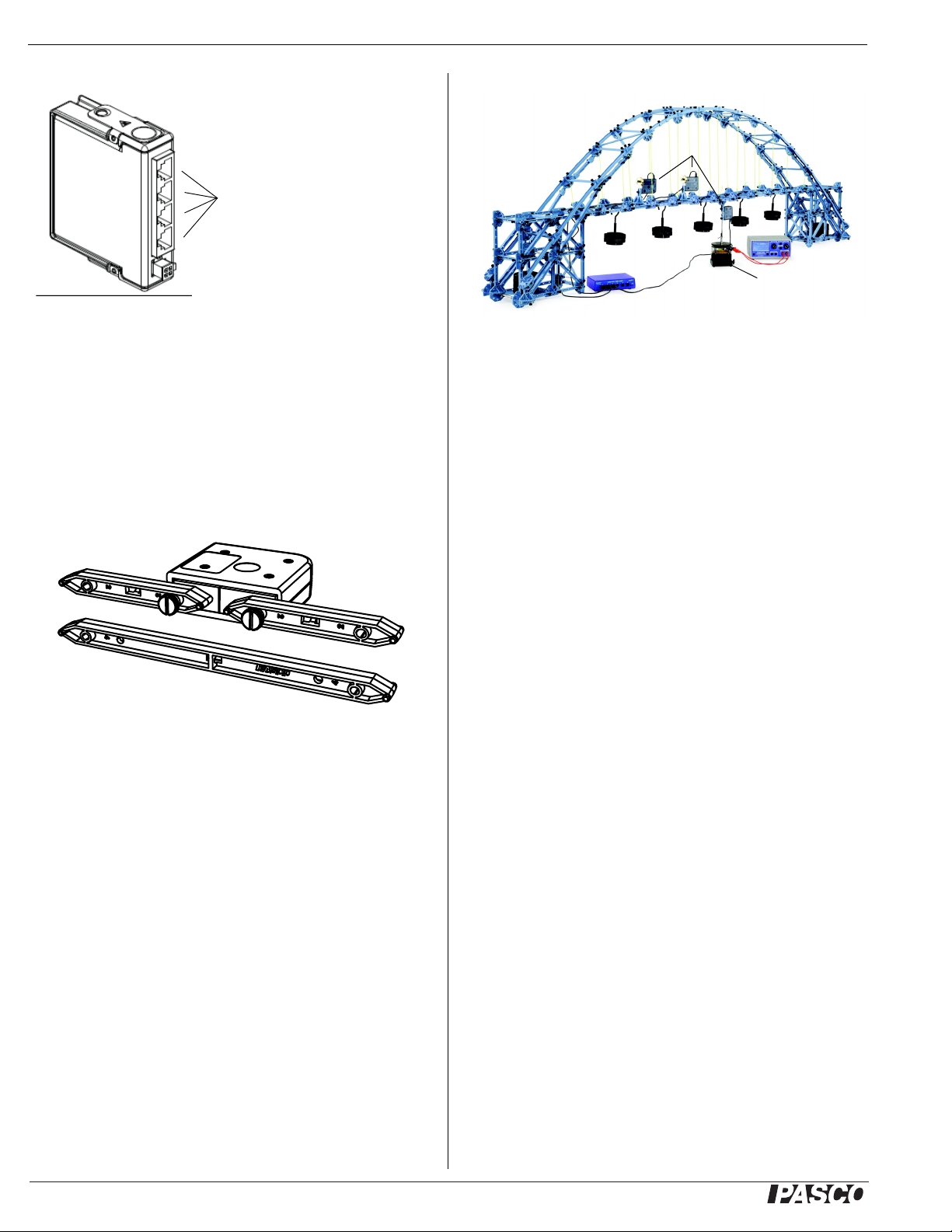
Figure 2: National Instruments NI-9237
Analog Input Module
RJ-50
Receptacles
SF-9324 Mechanical
Wave Driver
Load
Cells
Example: Bridge with Load Cells
Adding Load Cells
To measure the compression and tension forces in individual
members, add load cells to any PASCO Structure. Replace a
beam with two shorter beams and a load cell.
#5 beam = load cell + two #3 beams
#4 beam = load cell + two #2 beams
#3 beam = load cell + two #1 beams
Figure 3: A load cell combined with two #2 beams is the same length
as a #4 beam
Use thumbscrews to attach two beams to a load cell as shown in
Figure 3.
When using load cells, assemble your structure with the screws
loose. This will simplify the analysis by ensuring that the mem-
bers experience only tension and compression without moments.
Figure 4: Bridge with load cells
The bridge shown in Figure 4 incorporates two load cells to measure the tension or compression in various members amd a third
load cell to measure the shaking force provided by a mechanical
wave driver. Hanging masses are used to apply load. The
mechanical wave driver shakes the bridge structure at a controlled frequency.
Combination of Load Cells
The 5 N Load Cell can be used in combination with other 5 N
Load Cells or with 100 N Load Cells (PS-2200-NI).
Calibration of Load Cells
Load cells are factory calibrated; however, you can recalibrate
them in software or on a datalogger. See the documentation for
your software or datalogger for instructions.
When calibrating a load cell, it is necessary to apply a known
load. Assemble the fixture shown in Figure 4 to support the load
cell. Hold or clamp the fixture at the edge of a table and hang a
mass from it as shown.
Note that the hanging mass applies tension to the load cell; therefore the known force that you enter into the software or datalogger should be a negative value. For example, if the mass is 0.5 kg,
the applied force is -4.9 N.
Plug the RJ-50 connector at the end of the load cell cable into a
port on the NI-9237 Analog Input Module. See the instructions
that came with the Analog Input Module for details about how to
connect the load cell.
For more information about National Instruments hardware and
graphical programming environment, see the web site:
www.ni.com
2
Page 3

®
Load Cell, 5 N (NI) PS-2201-NI
Half Round
Connector
The NI Driven Structures Set (ME-7007) consists of:
• ME-6987 Flat Beams (1 set)
• ME-6993 Truss Set Members (8 sets)
• ME-6994 Truss Set Screws (14 sets)
• ME-6996 Cord Lock Spares (2 sets)
• ME-6997 Round Connectors (2 sets)
• ME-6999A Angle Connectors (2 sets)
• ME-7002 Connector Spares (4 sets)
• ME-6988 Force Platform Bracket (4)
• ME-7589 Short Slotted Mass Set (4 sets)
• ME-7590 Short Slotted Mass Hanger (6)
• SE-9750 Long Patch Cords (set of 5)
• PI-2212 Instrument Amplifier (1)
Figure 5: Calibration fixture
Other
The NI Structures Set (ME-7006) consists of the following:
• ME-6987 Flat Beams (1 set)
• ME-6993 Truss Set Members (3 sets)
• ME-6994 Truss Set Screws (5 sets)
• ME-6996 Cord Lock Spares (1 set)
• ME-6997 Round Connectors (1 set)
• ME-7002 Connector Spares (2 sets)
• ME-6988 Force Platform Bracket (2)
• ME-7589 Short Slotted Mass Set (4 sets)
• ME-7590 Short Slotted Mass Hanger (6)
• PS-2201-NI 5 N Load Cell (4)
• PS-2200-NI 100 N Load Cell (1)
• PS-2201-NI 5 N Load Cell (10)
• SF-9324 Mechanical Wave Driver (1)
3
Page 4

®
Load Cell, 5 N (NI) PS-2201-NI
Pin Wire Color
1 NC (not connected)
2Black
3Red
4NC
5NC
6Brown
7 Orange
8NC
9NC
10 Shield
Pin 1Pin 10
Pin 1
Pin 10
To p
view
Front view
Specifications
Range -5 N to +5 N
Resolution 0.001 N
Dimensions 5.3 cm by 5.8 cm by 2.0 cm
Length of cable 120 cm (1.2 m)
Mass approximately 100 g (0.1 kg)
Pinouts
Technical Support
For assistance with any PASCO product, contact PASCO at:
Limited Warranty For a description of the product warranty, see the
PASCO catalog. Copyright The PASCO scientific 012-11989A Load
Cell, 5 N (NI) Instruction Sheet is copyrighted with all rights reserved. Permission is granted to non-profit educational institutions for reproduction of
any part of this manual, providing the reproductions are used only in their
laboratories and classrooms, and are not sold for profit. Reproduction
under any other circumstances, without the written consent of PASCO scientific, is prohibited. Trademarks PASCO and PASCO scientific are
trademarks or registered trademarks of PASCO scientific, in the United
States and/or in other countries. All other brands, products, or service
names are or may be trademarks or service marks of, and are used to
identify, products or services of, their respective owners. For more information visit www.pasco.com/legal.
Patents Pending The following PASCO products have patents pending:
ME-6985 Flexible I-Beams Set0
ME-6987 Flat Beams Set
ME-6989 Physics Structures Set
ME-6990 Truss Set
ME-6991 Bridge Set
ME-6992A Advanced Structures Set
ME-6995 Road Bed Spares
ME-7009 Cast Beam Structures Set
Product End of Life Disposal Instructions: This electronic product is
subject to disposal and recycling regulations that vary by country and
region. It is your responsibility to recycle your electronic equipment per
your local environmental laws and regulations to ensure that it will be recycled in a manner that protects human health and the environment. To find
out where you can drop off your waste equipment for recycling, please
contact your local waste recycle/disposal service, or the place where you
purchased the product. The European Union WEEE (Waste Electronic
and Electrical Equipment) symbol (below) and on the product or its packaging indicates that this product must not be disposed of in a standard
waste container.
Address: PASCO scientific
10101 Foothills Blvd.
Roseville, CA 95747-7100
Phone: 916-786-3800 (worldwide)
800-772-8700 (U.S.)
Fax: (916) 786-7565
Web: www.pasco.com
Email: support@pasco.com
For the latest revision of this Instruction Sheet, visit:
www.pasco.com/go?PS-2201-NI
4
 Loading...