

Page 1
PASCO Structures System
®
5 N Load Cell
Load Cell, 5 N
PS-2201
fier, the Load Cell can measure compression and tension forces
in any component of the PASCO Structures System.
For example, the PASCO Structures System includes the
ME-6987 Flat Structures Members, ME-6990 Truss Set,
ME-6991 Bridge Set, and the ME-6992 Advanced Structures Set.
About the Load Cell
The PS-2201 Load Cell measures forces ranging from -5 N to
+5 N and is wired with a male 6-pin mini-DIN connector for
plugging into a Load Cell Amplifier.
Instruction Sheet
012-11097A
*012-11097*
Recommended Equipment
• Load Cell Amplifier (PS-2198) or Dual Load Cell
Amplifier (PS-2205)
• PASPORT Interface or SPARK SLS
Related Equipment
• Complete Structures Set (ME-6989)
• Truss Set (ME-6990)
• Bridge Set (ME-6991)
• Advanced Structures Set (ME-6992)
• Load Cell & Amplifier Set (PS-2199)
See www.pasco.com for details about PASPORT equipment and PASCO
Structures System parts and sets.
Introduction
The Load Cell, 5 N is designed to work with the PASCO Structures System. When connected to a PASCO interface through the
PS-2198 Load Cell Amplifier or PS-2205 Dual Load Cell Ampli-
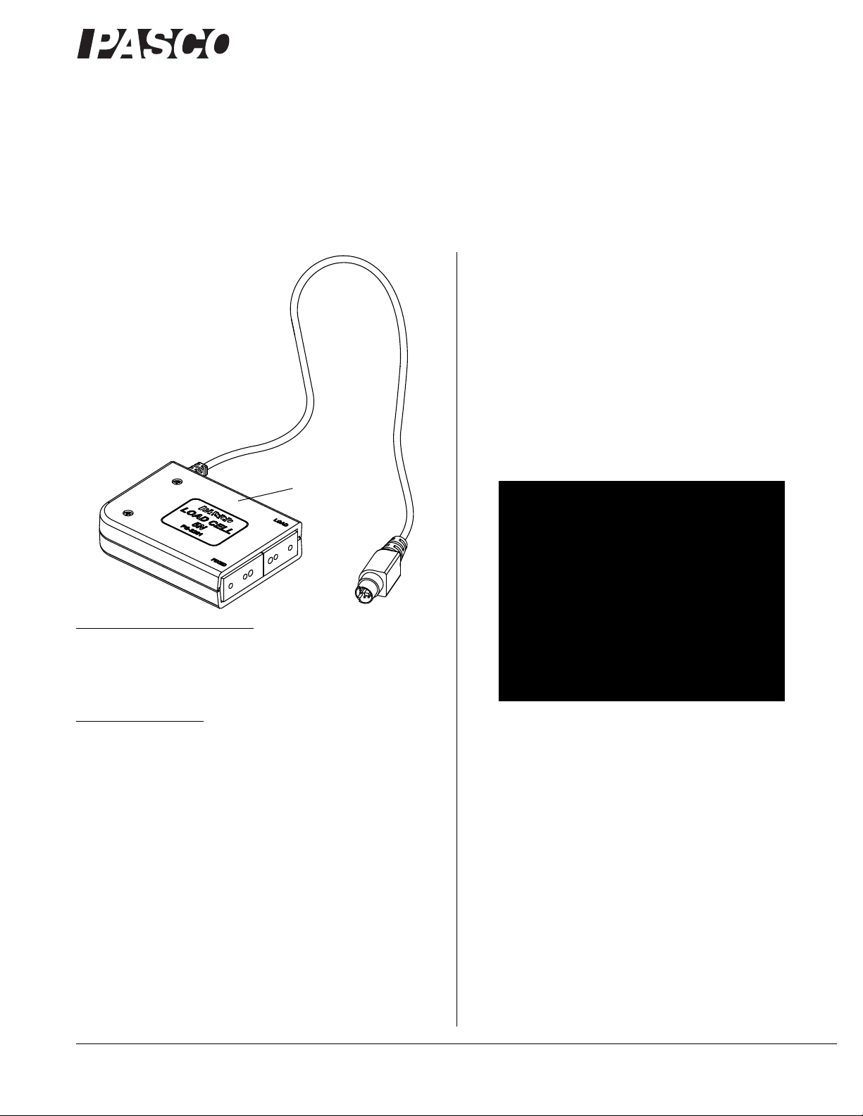
Figure 1: The 5N Load Cell has a semi-transparent case
The PS-2198 Load Cell Amplifier supports up to six Load Cells.
The PS-2205 Dual Load Cell Amplifier supports two Load Cells.
The PS-2199 Load Cell and Amplifier Set includes one Load
Cell Amplifier and four 100 N Load Cells.
Adding Load Cells
To measure the compressio n and tension forces in individual
members, add load cells to any PASCO Structure. Replace a
beam with two shorter beams and a load cell.
#5 beam = load cell + two #3 beams
#4 beam = load cell + two #2 beams
#3 beam = load cell + two #1 beams
800-772-8700 www.pasco.com
Page 2

®
Load Cell, 5 N PS-2201
1.0 N21.0 N
2
+ 1.4 N=
Calibration of Load Cells
Load cells are factory calibrated; however, you can recalibrate
them in software or on the datalogger. See the documentation for
your software or datalogger for instructions.
When calibrating a load cell, it is necessary to apply a known
load. Assemble the fixture shown in Figure 4 to support the load
cell. Hold or clamp the fixture at the edge of a table and hang a
mass from it as shown.
Figure 2: A load cell combined with two #2 beams is the same length
as a #4 beam
Use thumbscrews to attach two beams to a load cell as shown in
Figure 2.
When using load cells, assemble your structure with the screws
loose. This will simplify the analysis by ensuring that the mem-
bers experience only tension and compression without moments.
Plug the mini-DIN connector at the end of the load cell cable into
a port on the Load Cell Amplifier. See the instructions that came
with the load cell amplifier for details about how to connect the
load cell amplifier to an interface or datalogger and collect data.
Note that the hanging mass applies tension to the load cell; therefore the known force that you enter into the software or datalogger should be a negative value. For example, if the mass is 0.5 kg,
the applied force is -4.9 N.
Example: Bridge with Load Cells
Figure 3: Bridge with load cells
The bridge shown in Figure 3 incorporates six load cells to measure the tension or compression in various members. A hanging
mass is used to apply load. The mass is adjusted so that the compression in one of the legs is 1.0 N. Compression is registered as
a positive value and tension as a negative value.
If the screws are loose, the theoretical analysis of the bridge can
be carried out by assuming that the net force at each node is zero.
Thus, the vertical component of compression in the left-most
diagonal member must be 1 N (to oppose the force applied by the
leg). The horizontal component must also be 1 N since the member is at a 45° angle. The predicted resultant force is:
Figure 4: Calibration fixture
Specifications
Range -5 N to +5 N
Resolution 0.001 N
Dimensions 5.3 cm by 5.8 cm by 2.0 cm
Length of cable 120 cm
The actual measured force confirms the theory.
Combination of Load Cells
The 5 N Load Cell can be used in combination with other 5 N
Load Cells or with 100 N Load Cells (PS-2200).
2
Mass approximately 100 g
Page 3

®
Load Cell, 5 N PS-2201
2
1
3
5
4
6
Pinouts
Pin Signal
1 + Strain Gauge Output
2 + 4.2 V
3 - Strain Gauge Output
4 Ground
5 Range Select 1
6 Range Select 2
Technical Support
For assistance with any PASCO product, contact PASCO at:
Address: PASCO scientific
10101 Foothills Blvd.
Roseville, CA 95747-7100
Phone: 916-786-3800 (worldwide)
800-772-8700 (U.S.)
Fax: (916) 786-7565
Web: www.pasco.com
Email: support@pasco.com
For the latest revision of this Instruction Sheet, visit:
The European Union WEEE (Waste Electronic and Electrical
Equipment) symbol (below) and on the product or its packaging
indicates that this product must not be disposed of in a standard
waste container.
www.pasco.com/go?PS-2201
Limited Warranty For a description of the product warranty, see the
PASCO catalog. Copyright The PASCO scientific 012-11097A Load
Cell, 5 N Instruction Sheet is copyrighted with all rights reserved. Permission is granted to non-profit educational institutions for reproduction of any
part of this manual, providing the reproductions are used only in their laboratories and classrooms, and are not sold for profit. Reproduction under
any other circumstances, without the written consent of PASCO scientific,
is prohibited. Trademarks PASCO and PASCO scientific are trademarks or registered trademarks of PASCO scientific, in the United States
and/or in other countries. All other brands, products, or service names are
or may be trademarks or service marks of, and are used to identify, products or services of, their respective owners. For more information visit
www.pasco.com/legal.
Patents Pending The following PASCO products have patents pending:
ME-6987 Flat Structures Members PS-2198 Load Cell Amplifier
ME-6990 Truss Set PS-2199 Load Cell and Amplifier Set
ME-6991 Bridge Set PS-2200 100 N Load Cell
ME-6992 Advanced Structures Set PS-2201 5 N Load Cell
ME-6995 Road Bed Spares PS-2205 Dual Load Cell Amplifier
Product End of Life Disposal Instruc tions:
This electronic product is subject to disposal and recycling regulations that vary by country and region. It is your responsibility to
recycle your electronic equipment per your local environmental
laws and regulations to ensure that it will be recycled in a manner
that protects human health and the environment. To find out
where you can drop off your waste equipment for recycling,
please contact your local waste recycle/disposal service, or the
place where you purchased the product.
3
 Loading...