

Page 1

Instruction Manual
Manual No. 012-08279B
Visual
Accelerometer
Model No. PS-2128
Page 2

Page 3

Visual Accelerometer Model No. PS-2128
Table of Contents
Equipment List........................................................... 3
Introduction ............................................................. 4
Operation Requirements and Procedures .............................. 4
Turning On the Visual Accelerometer...........................................................................................4
Turning Off the Visual Accelerometer..........................................................................................5
Battery Life and Power..................................................................................................................5
Inserting/Replacing the Batteries...................................................................................................6
Zeroing the Visual Accelerometer.................................................................................................6
Operating the Visual Accelerometer..............................................................................................7
The Visual Acceleration Scale .......................................................................................................7
Selecting a Visual Acceleration Scale ...........................................................................................8
-Full Scale............................................................................................... ...... ...... .......................8
-Manual Scale ............................................................................................................................8
-Auto Scale.................................................................................................................................8
-Peak Hold .................................................................................................................................9
Using the Visual Accelerometer with DataStudio® Software ........ 9
Using the Visual Accelerometer with a PASPORT™ Xplorer ........10
Setup Options ..........................................................11
1) Visual Accelerometer on an Inclined Track............................................................................11
2) Visual Accelerometer with Mass Bars and Picket Fence (Photogate Studies)........................12
3) Visual Accelerometer and Force Sensor (Newton’s Law Studies) ......................................... 12
4) Visual Accelerometer with Fan Accessory (with Time Pulse)................................................13
5) Visual Accelerometer on a Motorized Cart (with Time Pulse)...............................................13
6) Visual Accelerometer with Friction Accessory.......................................................................14
7) Visual Accelerometers on Colliding Carts (Collision Studies)...............................................14
8) Visual Accelerometer and Spring Oscillations........................................................................15
9) Visual Accelerometer and Pendulum (Horizontal Orientation) ..............................................15
10) Visual Accelerometer and Pendulum (Vertical Orientation).................................................16
11) Visual Accelerometer Parallel to Pendulum..........................................................................16
12) Visual Accelerometer Clamped to a Rod Stand....................................................................17
13) Visual Accelerometer Hanging from a Rope.........................................................................18
14) Visual Accelerometer on a Rotating Platform ......................................................................18
Appendix A: Specifications............................................ 19
Appendix B: Troubleshooting .......................................... 20
Appendix C: Technical Support ....................................... 21
Appendix D: Copyright and Warranty Information .................. 22
2
®
Page 4
Model No. PS-2128 Visual Accelerometer
Visual Accelerometer
Model No. PS-2128
Equipment List
1
Included Equipment Replacement
1. Visual Accelerometer (1)
2. PASPORT™ extension cable, 5.5 feet (1)
3. Batteries, AA size, alkaline (4) (Note: Only 3 are required for operation.)
4. Thumbscrews (4)
2
3
4
Model Number*
PS-2128
514-07281
617-018
*Use Replacement Model Numbers to expedite replacement orders.
NSS
Additional Equipment Recommended
Visual Accelerometer Accessory Kit (See page 11 for an itemized list.)
USB link or Xplorer
DataStudio software (version 1.6 or later)
A USB-compatible computer
NSS = not sold separately from PASCO
NA = not available for sale from PASCO
®
PS-2516
PS-2100 or PS-2000
CI-6870C
NA
3
Page 5
Visual Accelerometer Model No. PS-2128
Introduction
The Visual Accelerometer is a sensor designed for visual
demonstration of acceleration along a horizontal axis. The Visual
Accelerometer can be inserted into the top of any PASCO dynamics
cart, PAScar, or GOcar or used by itself for acceleration studies.
Green and red lights on the Accelerometer illuminate to indicate
positive or negative increments of acceleration (in either units of m/s/s
or g). The scale range and resolution can be controlled through either
an auto or manual scale switch. A “Peak Hold” switch allows the user
to capture the display of maximum acceleration.
The Visual Accelerometer can also be used with DataStudio software
to measure or graph acceleration changes. The Visual Accelerometer
is ideal for the study of Newton’s law with carts and tracks, collision
experiments, and rotational motion studies.
Operation Requirements and Procedures
Operation Requirements: The Accelerometer requires 3 “AA”
alkaline cells and/or USB power . USB operation requires a PASPOR T
USB link (PS-2100) and DataStudio software or a PASPORT Xplorer
(PS-2000).
Turning on the Visual Accelerometer
Fig. 1a
Step: Push in and
release the black button.
Fig. 1b
Green lights
Fig. 1c
red lights
If the Accelerometer is
plugged into a USB Link
or Xplorer, the battery
test (five alternating
flashing red and gr een
lights) does not occur at
turn on.
Result: When you release the button, five green and red lights
illuminate and turn off. (Note: At turn on, the alternating of five
flashing red and green lights is the battery test, which only occurs
during battery operation.)
4
®
Page 6
Model No. PS-2128 Visual Accelerometer
Turning off the Visual Accelerometer
Fig. 2a
Step: Press and hold the black
button until two red and two green
Fig. 2b
Result: When you release the
button, the sensor turns off.
lights illuminate.
Note: If the unit ever fails to turn on or off using the push-button
switch, open the case and remove any battery for a few seconds, then
reinstall. The unit should operate normally.
Battery Life and Power
The unit has a internal timer that will automatically turn power off
after three hours, even if the unit is being used at the time. To resume
operation, just press the black push button (also called the ON/ZERO/
OFF button).
When the unit is powered from a USB port or hub, the unit cannot be
turned off and the 3-hour automatic-off feature stops functioning.
When you disconnect the unit from USB power , the push button on-of f
and auto-off timer functions operate normally.
When the Accelerometer is turned off, it draws only a fraction of a
milliamp from the batteries. Under intermittent operating conditions,
battery life is 6-9 months (with the batteries installed). If you do not
expect to use the unit for several weeks, always remove the batteries;
this can increase the battery life to years and reduce the risk of leaky
batteries damaging the unit.
Note: Always fasten the
V isual Accelerometer to a
steady base, such as a
dynamics cart, to prevent
noise from the LEDs
(light-emitting displays).
With battery-powered operation, a battery test occurs every time you
turn on the Accelerometer and release the button. If the battery test is
okay, you will see the green and red lights turn briefly on and off. (If
the red and gr een lights continue to alternately flash for a few seconds,
you have a low battery condition). (Note: If the Accelerometer is
connected to a USB Link or Xplorer and turned on, the battery test
does not occur.)
®
5
Page 7
Visual Accelerometer Model No. PS-2128
Inserting/Replacing the Batteries
When the Accelerometer is operating on batteries alone, a battery test
is performed when you turn on the unit. When the first red and first
green light on each scale alternately flash on and off, you have a low
battery condition. To replace the batteries, do the following:
1. Turn the power off and/or disconnect the PASPORT extension cable.
CAUTION: In the case of a malfunction, do not tamper with any of
the internal components on the circuit board of the Visual
Accelerometer. Refer to the T roubleshooting section (Appendix B) or
call Technical Support for assistance or a replacement (See
Appendices C and D).
2. Loosen the screws on the underside of the casing.
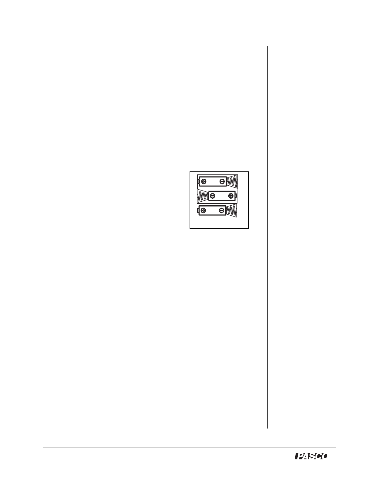
3. Remove the bottom casing and replace the
batteries in the orientation shown in Figure
3. (Note: The Accelerometer will turn on
as the last battery is installed.)
4. Realign the bottom casing with the top
casing. Replace the screws and tighten.
Figure 3
Zeroing the Visual Accelerometer
The Visual Accelerometer was calibrated at the factory and does not
require calibration. However, if you plan to use the Visual
Accelerometer in an inclined (or other than horizontal position), you
should always zero the Accelerometer in the same position that you
plan to use during an experiment.
Note: The Visual Accelerometer only measures acceleration
measurements in a single plane. If you need to simultaneously
measure acceleration in multiple planes, order a PS-2118 or PS-2119
Acceleration Sensor from PASCO.
To zero the sensor:
1. Place the sensor in a resting position (in the same orientation that you
plan to use during the experiment).
2. Press and release the black button on the side of the sensor. (The
sensor requires about one second to complete the zeroing function.
Try not to move or jar the sensor during this operation.)
3. To verify the zero, open DataStudio and click the Start button. Your
reading should be zero.
6
®
Page 8
Visual Accelerometer Model No. PS-2128
Operating the Visual Accelerometer
1. a) For standalone use: Remove the case and install the batt erie s.
(See “Replacing the Batteries” on page 6 of this manual.)
OR
b) For use with DataStudio or Xplorer: Connect the receptacle
end of the PASPORT extension cable into the pin connector on
the top of the Accelerometer. Connect the plug on the opposite
end of the cable to either the USB link or the Xplorer.
2. Press in the black push button to turn on the Visual Accelerometer .
3. Move the scale switch to “Manual Scale.” Use the Full Scale
switch to select a full scale value (1, 5, or 20 m/s/s). (For more
information on scaling options, see “Selecting an Acceleration
Scale” in this manual.)
4. Use the provided thumb screws to fasten the Accelerometer to the
top of a PAScar, Dynamics Cart or GOcar.
5. Place the Visual Accelerometer in the desired orientation for your
experiment and push in the black button to zero the Accelerometer .
6. Move the cart and watch the display lights illuminate as you
accelerate the car in any direction.
The Visual Acceleration Scale
On the side of the Visual Accelerometer is the visual scale, the green
and red light-emitting displays for showing the amount of horizontal
acceleration.
negative scale (red)
Figure 4
positive scale (green)
Each light display represents a one-fifth (1/5) division of the maximum
on either the positive or negative scale.
7
®
Page 9

Visual Accelerometer Model No. PS-2128
Green lights - represent the positive horizontal acceleration scale (m/
s2). As acceleration increases in the positive direction, more green
lights turn on.
Red lights - represent the negative acceleration scale (m/s2). As
horizontal acceleration increases in the negative (or opposite
horizontal direction) more lights turn on.
Selecting an Acceleration Scale
Full Scale switch- Use this switch for selecting a scale: 0 to 1 m/s/s (0
to 0.1 g), 0 to 5 m/s/s (0 to 0.5 g), or 0 to 20 m/s/s (0 to 2 g). Each light
represents one-fifth (1/5) division of the maximum on the scale (See
examples below.)
1 m/s/s scale
m/s/s
-1.0 -0.8 -0.6 -0.4 -0.2
0.2 0.4 0.6 0.8 1.0
5 m/s/s scale
m/s/s
-5 -4 -3 -2 -1
1 2 3 4 5
Note: The V isual Acceler-
ometer only shows as
much acceleration as it
can detect. The number of
light displays lit reflects a
percentage of full scale:
1 light = 10-30%;
2 lights =30-50%;
3 lights = 50-70%;
4 lights = 70-90%,
5 lights = > 90%.
20 m/s/s scale
m/s/s
Figure 5
4 8 12 16 20-20 -16 -12 -8 -4
Manual Scale switch - Use this switch in conjunction with the full
scale switch for setting one of the three selectable scales (1 m/s/s, 10
m/s/s, or 20 m/s/s).
Auto Scale switch - Use this switch to set your own acceleration scale
for your experiment. Auto scale works only in the positive (green
LED) direction.
The Visual Accelerometer automatically determines the maximum
reading for the scale from the largest positive recorded acceleration
before the acceleration changes sign. The first four units on the
positive scale are 1/5, 2/5, 3/5, and 4/5 of the maximum reading in
m/s/s. The first four units on the negative scale are -1/5, -2/5, -3/5, and
-4/5 of the maximum reading in m/s/s. (Note: For a measurement of
the maximum reading, use Auto scale in conjunction with DataStudio
software.)
Note: The auto scale
reading is erased whenever you switch to manual
scale or peak hold. The
auto scale value is retained
if the unit is tu rned off
while in Auto Scale mode,
then turned back on with
the Function swit ch in the
same Auto Scale position.
8
®
Page 10

Model No. PS-2128 Visual Accelerometer
Peak Hold - Select this switch to tell the Accelerometer to search for
the peak acceleration and hold the display. Peak hold operates only in
the positive (green LED) direction. The peak hold only applies to the
peak in the acceleration before the acceleration changes sign. Before
switching to peak hold, set the full scale switch to the desired scale
resolution. To reset to a new peak hold, push in the black on/off
button. To stop the peak hold, move the switch back to manual or auto
scale.
Example: The Visual Accelerometer is set to the 20 m/s/s scale
resolution. The acceleration increases to 10 m/s/s, drops to 6 m/s/s,
increases to 14 m/s/s, then becomes negative. The Visual
Accelerometer holds the greatest acceleration (14 m/s/s) and four
green lights remain illuminated.
Using the Visual Accelerometer with
DataStudio
1. Connect a USB Link (PS-2100) to a USB port on your computer or to a
USB hub.
2. Connect the receptacle end of the PASPORT extension cable into
the pin connector on the top of the Accelerometer.
3. Connect the plug end of the PASPORT extension cable to a USB
Link.
4. When the PASPORTAL window launches, select DataStudio.
5. Use the black button to turn on and/or zero the Visual
Accelerometer. DataStudio will recognize the Visual
Accelerometer and a default Graph display will appear.
6. To collect data, click the Start button on the main tool bar.
Note: Depending on your experiment setup, you may need to clip the
PASPORT extension cable out of the way of the cart.
Changing Acceleration Units
The lights on the Visual Accelerometer reflect a m/s/s scale and
DataStudio automatically measures in the m/s/s scale. To measure in
units of “g” in DataStudio, use the PASPORT setup window.
®
9
Page 11

Visual Accelerometer Model No. PS-2128
To change acceleration units:
1. On the main toolbar, click the Setup button.
2. In the Experiment Setup window, click the Maximize button and
scroll to the Visual Accelerometer options.
3. Use the down arrow to select either the m/s/s or g units. When you
close out of this window, the unit change is automatically saved.
Using the Accelerometer with Xplorer
The Visual Accelerometer can be used with Xplorer in the classroom.
The extension cable supplied with the Accelerometer plugs into the
Xplorer and allows the user to move the Visual Accelerometer for a
distance of up to 5 ft. away from the Xplorer.
To collect data with Xplorer:
1. Plug the receptacle end of the P ASPORT extension cable into the
pin connector on the top of the Accelerometer.
2. Connect the other end of the extension cable to either the USB
link or the Xplorer.
3. To collect data, click the Start/Stop button. The LED
flashes when Xplorer is storing data. (To stop, click the Start/
Stop button again.
4. To view your data in DataStudio, connect the Xplorer cable to
the USB port on your computer and to the USB port on the side
of Xplorer.
Note: For acceleration studies of distances beyond five feet, we do not
recommend using the Visual Accelerometer with the PASPORT
extension cable because tension and/or tangling of the PASPORT
extension cable may affect the acceleration. In these cases, use the
Accelerometer as a standalone with internal battery power.
If using the Visual Accelerometer with an Xplorer, both devices must
have a power source (i.e. batteries installed). Using the Visual
Accelerometer without batteries (or external power) with a batterypowered Xplorer is not recommended due to the likelihood of
operational difficulties from inadequate power.
10
®
Page 12

Model No. PS-2128 Visual Accelerometer
Setup Options
The Visual Accelerometer can be mounted in various ways for studies
of linear, rotary, and centripetal acceleration, elastic and inelastic
collisions, friction, free fall, etc. The following paragraphs and
photographs describe some sample experiment setup options.
If you plan to use the Visual Accelerometer in various orientations,
consider purchasing a Visual Accelerometer Accessory Kit (PS-2516).
The Visual Accelerometer Accessory Kit includes the following:
1. Four String Pendulum Plate (1)
6
1
2. Plastic Rod Clamps (2)
3. M-5 plastic thumbscrews (2)
4. 1/4-20 plastic thumbscrews (4)
2
5. 1/4-20 square nuts (4)
6. Roll of thread (1)
3
4
5
Figure 1.0: Visual
Accelerometer Accessory
1) Visual Accelerometer on an
Kit
Inclined Track
Use the Visual Accelerometer with a Dynamics Track to study
acceleration changes on an incline. With the thumbscrews provided
with the Accelerometer, attach the Visual Accelerometer to a PAScar
or a Dynamics Cart.
Figure 1.1: Visual Accelerometer and Cart on an inclined track
A gentle slope is best because it gives the student more time to observe
the change in acceleration. Zero the Accelerometer on the incline.
Release the cart from rest or launch upwards.
Additional equipment required: Dynamics Track [1.2 (ME-9435A)
or 2.2 m (ME-9458)], Dynamics Cart (ME-9430) or PAScar (ME-
6950), Large Rod Base (ME-8735) and Steel Rod (ME-8738)
®
11
Page 13

Visual Accelerometer Model No. PS-2128
2) Visual Accelerometer
with Mass Bars and Pi cket
Fence (Photogate Studies)
The Visual Accelerometer
can be used with a picket
fence (flag) for photogate
studies. A mass bar can be
placed on the top of the
Accelerometer to study the
affect of mass on
acceleration. Use the
provided thumbscrews to
attach the Visual
Figure 1.2: V isual Accelerometer
with flag, mass, and PAScar
Accelerometer to a PAScar
or Dynamics Cart. The picket fence inserts directly into the side of a
PAScar or Dynamics Cart.
Additional equipment required: Dynamics Track [1.2m (ME9435A) or 2.2m (ME-9458)], Dynamics Cart (ME-9430), or PAScar
(ME-6950)
3) Visual Accelerometer and Force Sensor (Newton’s Law Studies)
When studying
Newton’s laws with a
Force Sensor on a cart,
add the Visual
Accelerometer to the
top of the sensor. The
Visual Accelerometer
attaches to the Force
Sensor with
Figure 1.3: Visual Accelerometer
on top of Force Sensor and PAScar
thumbscrews through
holes in the top of the
sensor (just like you would attach a Dynamics Cart or PAScar).
Additional equipment required: Dynamics Track [1.2m (ME9435A) or 2.2m (ME-9458)], Dynamics Cart (ME-9430) or PAScar
(ME-6950), Force Sensor (CI-6537), Visual Accelerometer with Fan
Accessory (ME-9491) and Time Pulse (ME-9496)
12
®
Page 14

Model No. PS-2128 Visual Accelerometer
4) Visual Accelerometer with Fan Accessory (and Time Pulse)
The Visual Accelerometer can be
used with the ME-9491 Fan
Accessory for motion and constant
acceleration experiments. Use the
provided thumbscrews to attach the
Visual Accelerometer to a PAScar or
Dynamics Cart. The Fan Accessory
clips onto the side rails of the Visual
Accelerometer the same as it does to
a Dynamics Cart or a PAScar. The
Time Pulse Accessory allows the fan
to turn on and off, hands free. Set the
Figure 1.4: Fan Cart on
Visual Accelerometer
time pulse for about 1 second. This
will give a short acceleration, and then show a constant speed as it
coasts the rest of the way down the track.
Additional equipment required: Dynamics Track [1.2m (ME9435A) or 2.2m (ME-9458)], Dynamics Cart (ME-9430) or PAScar
(ME-6950), Fan Accessory (ME-9491), Time Pulse Accessory (ME-
9496)
5) Visual Accelerometer on Motorized Cart (with Time Pulse
Accessory)
The Visual Accelerometer
can be used with the ME9781 Motorized Cart for
motion and constant velocity
experiments. The Visual
Accelerometer attaches to
the Motorized Cart with
thumbscrews through holes in
the top of the cart (the same
way you attach it to a
Dynamics Cart or a PAScar).
The Time Pulse Accessory
Figure 1.5: Visual Accelerometer
on a Motorized Cart
allows the cart to turn on and off, hands free. Set the Time Pulse for
about 2 seconds. This will give a very short acceleration (as it turns
on), and then show a constant speed for the two seconds. Watch for
the very short deceleration as it turns off.
Additional equipment required: Dynamics Track [1.2m (ME9435A) or 2.2m (ME-9458)], Motorized Cart (ME-9781), and Time
Pulse Accessory (ME-9496)
®
13
Page 15

Visual Accelerometer Model No. PS-2128
6) Visual Accelerometer with
Friction Accessory
To study the effect of friction on
acceleration, the Visual
Accelerometer has a recess in the
bottom that allows use of the
Friction Accessory (available for
the PAScar). The friction
accessory inserts through a hole in
the bottom of the PAScar. Make
sure you adjust the amount of
friction you want before you
fasten on the Visual
Figure 1.6: Visual
Accelerometer over a
PAScar with friction pad
Accelerometer.
Additional equipment required: Dynamics Track [(1.2 (ME-9435A)
or 2.2m (ME-9458)], PAScar (ME-6950), PAScar Friction Accessories
(ME-6952)
7) Visual Accelerometers on Colliding Carts (Collision Studies)
The Visual Accelerometer can be used in setups for either elastic or
inelastic collisions between carts on a track. With the thumbscrews
provided, attach a Visual Accelerometer to each cart and place both on
the track. Y ou can have both Accelerometers facing the same direction
for better visibility during a demonstration, but to use the PEAK
HOLD feature, the Accelerometers must face opposite directions, with
the red arrows pointing towards each other. Switch to PEAK HOLD
on both units at the same time. As the red lights count down, launch
the carts. The carts must collide after the red lights have finished
counting down. To repeat, leave the PEAK HOLD switch as it is, and
push the Start/Stop button. It will rest and start the red light
countdown. You can use the cart plunger or the magnetic end caps.
Add mass bars to change the conditions.
14
Figure 1.7: Using two PAScars and Visual
Accelerometers in a collision
®
Page 16

Model No. PS-2128 Visual Accelerometer
Additional equipment required: A second Visual Accelerometer
(PS-2128), Dynamics Track [(1.2m (ME-9435A) or 2.2m (ME-9458)],
Dynamics Carts (ME-9430) or PAScars (ME-6950)
8) Visual Accelerometer and Spring Oscillations
For oscillation or Newton’s Law studies, place the Visual
Accelerometer and Cart on a Dynamics Track. Connect springs from
the cart to the end stops on the Dynamics Track.
Figure 1.8: Visual Accelerometer over a
PAScar connected to track to springs
Use the provided thumbscrews to attach the V isual Accelerometer to a
PAScar or Dynamics Cart. Add mass bars to change the period.
Additional equipment required: Dynamics Track [(1.2m (ME9435A) or 2.2m (ME-9458)], Dynamics Cart (ME-9430) or PAScar
(ME-6950)
9) Visual Accelerometer and Pendulum (Horizontal Orientation)
This setup uses a pendulum clamp and thread to allow the Visual
Accelerometer to oscillate as a pendulum. Because the Visual
Accelerometer tips as it oscillates, the results may be surprising.
Compare the results of this setup to the Parallel Pendulum setup.
Figure 1.9a:Visual
Accelerometer used as a
pendulum (horizontal
orientation)
®
Figure 1.9b: Thread
looping through hole in
Visual Accelerometer
15
Page 17
Visual Accelerometer Model No. PS-2128
It is easier to adjust for level if you don’t tie the thread to the Visual
Accelerometer. Run the thread from the pendulum clamp down
through the loops (See Figure 1.9b) in the Visual Accelerometer and
then back up to the clam p. Zer o the Ac cele romet er wh en it i s at rest at
the bottom of its swing.
Additional equipment required: Pendulum Clamp (SE-9443)
Additional equipment recommended: Large Rod Base (ME-8735)
and Steel Rod (ME-8738)
10) Visual Accelerometer and
Pendulum (Vertical Orientation)
This setup uses a pendulum clamp
and thread to allow the Visual
Accelerometer to hang vertically. As
the V isual Accelerometer osci llates, it
measures the centripetal acceleration,
the acceleration parallel to the string.
It is easier to adjust for level if you
don’t tie the thread to the Visual
Accelerometer. Run the thread from
the pendulum clamp down through
the loops on the Visual Accelerometer
and then back up to the clamp. Zero
the Accelerometer (in its vertical
orientation) when it is at rest at the
bottom of its swing. Because the
Figure 1.10: Visual
Accelerometer used as a
pendulum (vertical
orientation)
Visual Accelerometer tips as it
oscillates, the results might be surprising. Compare the results of this
setup to the Parallel Pendulum setup. A more clear demonstration of
centripetal acceleration is described in the rotation setup on page 18,
using the Rotating Platform.
Additional Equipment required: Pendulum Clamp (SE-9443)
Additional equipment recommended: Large Rod Base (ME-8735)
and Steel Rod (ME-8738)
11) Visual Accelerometer Parallel to Pendulum
This setup keeps the Visual Accelerometer level as it oscillates by
using the special four string pendulum plate from the Visual
Accelerometer Accessory Kit. The Ac celeromet er correctly shows the
horizontal acceleration as it oscillates. It is easier to adjust for level if
you don’t tie the thread to the Visual Accelerometer. Run the thread
16
®
Page 18

Model No. PS-2128 Visual Accelerometer
from the pendulum plate down through the loop on the Visual
Accelerometer (see Figure 1.11b) and then back up to the plate. Zero
the Accelerometer when it is at rest at the bottom of its swing.
Figure 1.11b: Thread-
Figure 1.11a:Visual
Accelerometer Swinging
forming loop through hole
in Accelerometer
Parallel to Rod Stand
Additional equipment required: Visual Accelerometer Accessory
Kit (PS-2516)
Additional equipment recommended: Large Rod Base (ME-8735)
and Steel Rod (ME-8738)
12) Visual Accelerometer Clamped to a Rod Stand
To use the Visual
Accelerometer
inside another
moving reference,
such as an elevator,
best results are
obtained if the unit
is mounted to a
stand. Use the two
black, plastic rod
clamps from the
Visual
Accelerometer
Figure 1.12a: Visual
Accelerometer
clamped to a rod
Figure 1.12b:
Close-up of clamps
Accessory. Insert
two 1/4-20 plastic thumb screws through the top of the Accelerometer
case, and securely fasten the clamps.
®
17
Page 19

Visual Accelerometer Model No. PS-2128
There is a ridge on the bottom of the case (Figure 1.12b) to help align
the clamps square to the case. Zero the Accelerometer in its vertical
orientation.
Additional equipment required: Visual Accelerometer Accessory
Kit (PS-2516)
Additional Equipment Recommended: Small Base and Support Rod
(SE-9451)
13) Visual Accelerometer Hanging
from a Rope (Free Fall)
For free fall studies, the bottom of the
Visual Accelerometer has a channel
that accepts a cord or a small rope. By
running the rope through a foam
cushion at the bottom, you can allow
the Accelerometer to free fall. Zero
the Accelerometer in its vertical
orientation.
Additional equipment
recommended: No bounce pad
(SE-7347)
Figure 1.13: Visual
Accelerometer
threaded from a rope
14) Visual Accelerometer on
Rotating Platform
The Visual Accelerometer
attaches to the Rotating
Platform for centripetal
acceleration studies. Use two
1/4-20 plastic thumbscrews
and two square nuts from the
Visual Accelerometer
Accessory Kit. The square
nuts fit into the T-slot (Figure
1.14) in the platform. Y ou can
use either the slot in the top or
Figure 1.14: Visual
Accelerometer rotating on a
platform
slot in the side. For the exact
center point of the sensor, see the Specifications in Appendix A.
Additional equipment required: Rotating Platform (ME-8951)
18
®
Page 20

Model No. PS-2128 Visual Accelerometer
Appendix A: Specifications
Visual Accelerometer:
Sensor range: Manual scale:
±1, ±5, ±20 m/s/s)
(
Auto scale:
Maxim um acceleration
measurement:
Maxim um acceleration
without damage:
Accuracy: ±0.02 g (0.2 m/s/s)
Resolution: LEDs: 20% of full scale range
Default sample rate: 50 samples/sec
Maxim um sample rate: 100 samples/sec
Frequency response: 0 to 10 Hz
Power required: 3 “AA” alkaline cells and/or USB link
Dimensions: length: 5.80”; width: 2.47”; height: 1.8”
±2 g (20 m/s/s), single axis
1000 g (10,000 m/s/s)
DataStudio output: 0.001 g (0.01 m/s/s)
±0.1 g, ±0.5 g, ±2 g
±0.02 to ±2 g (±0.2 to ±20 m/s/s)
The center of the sensor is
indicated by the red dot on the
top label of the Visual
Accelerometer.
®
19
Page 21

Visual Accelerometer Model No. PS-2128
Appendix B: Troubleshooting
Problem Possible Cause(s) Possible Solution(s)
One or more lights
flicke r, regardles s of
the direction of
movement.
One red and one
green light
alternately flash at
turn on.
Accelerometer does
not turn on.
Accelerometer does
not turn off.
Accelerometer does
not respond to
acceleration or
changing switch
positions.
The Accelerometer is in
an unstable position or
you have a low battery
condition.
Batteries are low. Open the bottom casing and replace
Low batteries or incorrect
turn on.
USB power is still
connected; incorrect turn
off procedure;
Accelerometer is locked
up.
Weak batteries or
electrostatic discharge
cause the Accelerometer
to lock up.
Prior to using the Visual
Accelerometer, use the thumbscrews
to mount it to a cart or a steady base.
Replace the batteries.
the batteries. (See pages 5-6.)
Replace the batteries. Check battery
orientation. (See page 6.) (For
instructions on how to turn on the
Accelerometer, see page 4.)
Disconnect the USB link from the
Accelerometer. (For instruction s on
how to turn off the Accelerometer, see
page 5.) If the unit still does not turn
off, remove one battery for a few
seconds; then replace it.
If the batteries are good, remove one
battery for a few seconds, and replace
it. Otherwise, install three new
batteries.
Positive and
negative light
scales appear to
work in reverse of
the direction of
acceleration.
Auto scale reading
is erased.
20
Improper zeroing or unit
malfunction.
Moving the scale switch
back and forth.
Zero the Accelerometer in the same
position that you plan to use it during
the experiment. See zeroing
instructions on page 6. Verify the zero
reading in DataStudio.
To retain the auto scale reading, turn
the unit off while in autoscale; then
turn the unit back on.
®
Page 22

Model No. PS-2128 Visual Accelerometer
Appendix C:Technical Support
For assistance with the PS-2128 Visual Accelerometer or any other
PASCO products, contact PASCO as follows:
Address: PASCO scientific
10101 Foothills Blvd.
Roseville, CA 95747-7100
Phone: (916) 786-3800
FAX: (916) 786-3292
Web: www.pasco.com
Email: techsupp@pasco.com
®
21
Page 23

Visual Accelerometer Model No. PS-2128
Appendix D: Copyright and Warranty
Information
Copyright Notice
The PASCO scientific 012-08279A Visual Accelerometer Manual is
copyrighted and all rights reserved. However, permission is granted to
non-profit educational institutions for reproduction of any part of the
012-08279A Visual Accelerometer Manual, providing the
reproductions are used only for their laboratories and are not sold for
profit. Reproduction under any other circumstances, without the
written consent of PASCO scientific, is prohibited.
Limited Warranty
PASCO scientific warrants the product to be free from defects in
materials and workmanship for a period of one year from the date of
shipment to the customer. PASCO will repair or replace, at its option,
any part of the product which is deemed to be defective in material or
workmanship. The warranty does not cover damage to the product
caused by abuse or improper use. Determination of whether a product
failure is the result of a manufacturing defect or improper use by the
customer shall be made solely by PASCO scientific. Responsibility
for the return of equipment for warranty repair belongs to the
customer. Equipm ent must be properly packed to prevent damage and
shipped postage or freight prepaid. (Damage caused by improper
packing of the equipment for return shipment will not be covered by
the warranty.) Shipping costs for returning the equipment after repair
will be paid by PASCO scientific.
22
®
Page 24

 Loading...